SEARCH FINESCALE.COM

Enter keywords or a search phrase below:

1/6th scale RC M4A3 Sherman project

20258 views
25 replies
1 rating 2 rating 3 rating 4 rating 5 rating
  • Member since
    April 2005
1/6th scale RC M4A3 Sherman project
Posted by armourguy on Tuesday, March 15, 2011 8:53 PM

Hi Guys, Now that the jeep and schwimmwagen quick builds are out of the way I have now rolled up my sleeves and dug into this new RC Vantex / Fuyuan M4A3 Sherman.

For those who haven't heard of these models before these kits were released last fall and I posted a out of the box first look review here 

http://www.sixtharmygroup.com/forums/general-quarters/14231-chinese-gas-rc-sherman-3.html 

I have also got the model up and running and I posted a review, and footage of the tank driving up on youtube.

http://www.youtube.com/watch?v=eLBE01VoOfA

http://www.youtube.com/watch?v=qQZEZms3J0E

http://www.youtube.com/watch?v=lTI-F50UyGs

For the tank's speed controller I used this electronic speed controller from VANTEC. To avoid any confusion the tank model is made by VANTEX/FUYUAN from China, The Speed controller is made by VANTEC speed controller company based and made in the USA. The two companies are NOT related. The speed controller works off of one radio stick and was very easy to hook up to the tank's electrical system.

For the Battery I used this 12V 14AH battery. The whole tank runs well on this one battery.


After the tank was tested it was evaluated and marked up on what parts will be kept and what will be replaced.


Before I started to cut into the tank, I needed to add jacks to the wires that connected the turret rotation motor and the gun elevation motor to the tank's lower hull. The tank out of the box has the wires connected with no way of disconnecting them. Now with the jacks I can fully remove the upper hull from the lower hull when I need to get access into the tank.

When gutting the tank I used the Dremel multimaster to remove the lion's share of the molded in parts. Most of the gutting is complete and I will now be able to start the rebuild.  

I removed the gun from the turret to get access to the turret for the rebuild. The gun will be reinstalled to the turret with the correct style slot screws rather than the Phillip’s head screws that were used in the kit. With the gun removed from the turret allows you to get a good look of the gun elevation system.  

Now that the gutting is mostly completed I will start by fabricating the tank's sponsons and other missing hull sections. More info to come.

  • Member since
    January 2010
  • From: St. Louis
Posted by Shawn M. on Wednesday, March 16, 2011 7:15 AM

looking forward to following along, your builds are always amazing.

I love the smell of plastic in the morning

  • Member since
    April 2005
Posted by armourguy on Sunday, March 20, 2011 8:25 PM

Thanks Shawn,

I have made some progress on the model.


Before I started to rebuild the hull I wanted to modify the way the gear box was installed to the hull. On the stock tank the gearbox is bolted securely to the hull via 6 Allen screws with nylock nuts. The problem with the way they are installed is that the nuts and threads are stick out of the lower hull and are not only quite noticeable, but will snag debris when driving.


To fix this I first replaced the front three Allen screws with hex bolts that were mounted into counter sinks that were drilled into the hull. Rather than having the nuts on the outside I rotated them leaving them on the inside and the flatter hex head mounted more flush with the exterior than the Allen screw. These bolts will be covered up once I start on the transmission cover's body work, which will be next.


For the second row I simply switched the bolt's orientation. Now the threaded portions are on the inside and the bolt heads on the outside. No counter sinks were needed because of their location their heads will not be seen.


Once the gear box fasteners were corrected I then moved towards replacing the large missing sections of the front hull. The stock kit has these portions removed so they can insert the gearbox like the way they are installed on an old tamiya 1/35th scale model.  This leaves two gaping holes on each side of the transmission. The transmission final drives were molded into the hulls side which also needed to be rebuilt. Two aluminum braces are bolted to the sides of the tank and act as a sturdy bulkhead.


This was the hardest part of the build. I had to first fabricate the missing hull sections, but I then had to fabricate the missing portion of the final drive. All of these parts had to blend in with the kit to be seamless. While installing the side plates I bolted them directly to the aluminum bulk head to secure them firmly. To make things a little easier I replaced the molded in nubs on the remaining final drives with real fasteners. Once the sponsons were fabricated I then added the top portion of the transmission cover mounting sections completed the transmission side rebuild


Once the side plates were wrapped up I then moved on to the fabrication of the sponsons. As I mentioned in the video the tank not only is missing the sponsons but the lower hull wall is too low. Which means if you look at the tank at a profile you will see a gap that runs through the other side. I encountered a similar problem on the Viper M4 and to correct the issue I performed the same procedure.


I first added a 1/2 inch strip of plywood to the hull sides extending them. I then fabricated the sponsons out of two strips of 1/4 inch plywood.


After these parts were mounted with fasteners I then applied fiberglass cloth to the inner portions of the sponsons. The cloth connects the wood to the rest of the GRP body adding strength. No cloth was added to the exterior. After the cloth was added then entire sponson, both interior and exterior was thoroughly soaked with fiberglass resin. Fusing the cloth and wood to the tank's body making it one. The resin that was applied to the exterior aids in strength, but also transforms the wood into plastic removing wood grain and making it more resilient to moisture and debris.


After the fiberglass work was complete I sprayed the interior with a coat of primer gray.


This completes the lower hull rebuilding. I will now be focusing on the transmission cover and the bogies, More info to follow! 


  • Member since
    April 2005
Posted by armourguy on Wednesday, March 23, 2011 9:29 PM

As a quick update, I completed the rework of the transmission cover.

On the stock transmission cover there are two wells that are molded in on either side of the cover. These wells are for the molded in fenders. Since I removed the fenders and will be using my own sheet metal ones these wells were no longer needed and were filled in.

On this model the transmission bolt strip is molded into the upper hull and is were the upper hull bolts to the lower hull. Because of this there will be a very significant seam line running through the cover. Since the tank is RC the upper hull will remain removable for gear box and maintenance access. Because of this the seam line will remain, the trick is to make the seam as faint and unnoticeable as possible. This was done with the way I applied the body work.

To rework the molded in bolt strip the edges were squared off with a dremel, also along the edges I etched the seam lines with the multimax. I also replaced the kit supplied brass lock bolts with 8-32 X 3/4 hex bolts, now the bolt strip has a better appearence than it's stock version. I still have to replace the other M2 X 6mm bolts currently on the strip with the same 3/4 hex bolts I used to mount the upper and lower hulls together so that all of the bolt strips bolts are all the same size. Once they arrive from my supplier I can add them.

Cast texture has been added to the entire transmission cover.

On the lower portion of the cover I etched the seam lines for the final drives, added the front foot steps, and cast numbers

I was also able to add the sponson access caps and weld beads.

Once the tank progresses the tow cable lock will be added. With the transmission out of the way I will now be focusing on reworking the bogies. I already have some new parts in molding and I should have some progress to post soon.  

  • Member since
    March 2010
Posted by shoot&scoot on Friday, March 25, 2011 6:53 PM

You may be able to benefit from an old model railroader's trick for powering the tracks on turntables.  You can use a male/female phono plug set for a commutator to the turret for the gun elevation motor.  This will allow for full 360 degree turret rotation and still allow for removal of the turret for maintenance.  Loved what you did on your previous builds and can't wait to see what you do with this one.

                                                                                                Pat

  • Member since
    April 2005
Posted by armourguy on Tuesday, March 29, 2011 9:20 PM

Thanks,

I have completed most of the suspension work. I will not be using my own suspension for this model, I found it to be too impractical to remove the securely mounted bogies from the hull. Instead I will be dressing up the kit bogies giving them a complete visual upgrade.


I have a few more mods to make to the bogies, but I have them mostly complete with only a few minor odds and ends to be added. This is also a sneak peak for the new vantex bogie upgrade kit.


To start with here is an image of the stock bogie. The stock bogie is the correct shape and scale. The details are very simple and leave room for improvement. As what was mentioned in the review the stock bogie's weakest part is the use of the shock absorber spring. On the real shermans the springs that were used were large clock work coil springs. 


To improve the look of the bogie I designed a spring and spring mount detail sleeve that fit over the kit shock absorber. The component master is made out of modified components that are used on my resin VVSS suspensions. The spring sleeves are designed to fit over the kit springs without any disassembly of the kit suspension. They also don't hinder any of the suspension's functionality. Once I have more parts I will add the springs to the product line.


Once the springs were completed I then turned my attention to the bogie's skid rail. The skid rail is made out of a solid billet of aluminum that was CNCed away leaving the center cavity. The kit skid rail is bolted on to the bogie top with two counter sunk screws. On real shermans the skid rail was a simple bent plate which was bolted onto the suspension with four bolts.


I decided to remove the skid rail and to delete the section of material that was on the skid rails bottom.


I also needed to mill away some material the was left on the end corner of the skid rail. A bench grinder can also be used if a Mill is not on hand. 


When I removed the skid rail off of the bogie housing I discovered that under each skid rail is a large square hole that is cut into the housing probably for spring clearance. 


To fix this I simply glued a thin sheet steel plate over each hole and added a little putty to smooth over everything.


To add the idler brace brackets I simply glued two styrene strips to each side of the bogie housing. After the body work, and added cast texture all of these parts blend in seamlessly.


When I remounted the rails I used the same stock bolts and bolt holes, but after the rails were mounted I epoxied over the bolts and sanded them down flush. Holes for the four hex bolts. The hex bolts are only for detail purposes. I was also able to cast the heads for the spring tension bolt covers that are found on the bogie housing top.  


On the aluminum swing arms, I removed the kit square nubs and added all of the bolt and nut details.


For the tank's idler mount I removed the molded in idler mount bulkhead braces and replaced them with resin parts that I removed off of my own resin braces. after some putty / cast texture work I added the idler mount / bogie housing seam line with the dremel multi max.


The the rear end of the bogie the housing is missiong it's rear wall. For this I recycled the alluminum strips that were removed off the skid rail bottoms and insterted them into the slot creating the wall. 


For the return rollers I added the zerk fittings, and zerk fitting indents. I also added the roller bearing ring which was also removed off of one of my roller castings.


One mistake that was made on my model was the first road wheel on the right hand side was mounted inverted, which means the detail portion of the road wheel was positioned towards the underbelly of the tank and the flat face was exposed. I tried to remove the wheel to turn it over but when doing this the bolts were tightened too much and were stripped


Instead of trying to dismantle the bogie and possibly damaging the swing arms I decided to fabricate the missing detail. To do this I casted one of my early spoke wheels partially so only half of the wheel was casted. Then I carefully cut out the center hub and the spokes on a scroll saw. Once removed I mounted the new detail spokes onto the kit wheel.


To finish off the suspension I will need to fabricate the wheel zerk fitting mounts and add lots of cast numbers to the suspension. Once I have the zerk mounts I will add the bogie detail upgrade to the product line. More to Come!


  • Member since
    April 2005
Posted by armourguy on Monday, April 11, 2011 7:14 PM

Hi guys, it's been awhile since I had any updates, but I have been working on tooling up the remainder of the boggie update components. The molding is all complete and I have added them to the product line and have completed the suspension rework.


All of the mods and details that were mentioned in the earlier post was added to the rest of the bogies including the cast numbers.


I also machined the absent zerk fittings and zerk fitting wells into both rear idler wheels.


The bogie detail dress up kits have been added to the product line.


Fuyuan / Vantex bogie detail dress up kit. This kit is designed to updetail the stock vantex sherman suspension. This set comes with the VVSS detail spring covers. The set also comes with the idler mount detail ribs and the road wheel zerk fitting mounts.


General 1/6th scale VVSS bogie dress up kit. This kit is designed to up detail other 1/6th scale VVSS bogies on the market (Plastic panzers, JD, ect). This set supplies you with the same parts as the set listed above, only the springs are casted in hard resin, and are not drilled out.


With the suspension out of the way I can pick up the pace on the model and focus on the rear wall details (exhausts, and engine hatch). More to follow.

  • Member since
    April 2005
Posted by armourguy on Wednesday, April 20, 2011 6:21 PM

I have been working on the rear wall detailing, and I have made some progress.


The original kit rear wall was very simplistic with very basic details. The details include basic tow hitch, basic exhausts stacks, and idler mounts. The model is missing the center engine hatch.


Most of these details were removed with the exception of the idler mounts and the tow hitch mount. The tow hitch mount is all steel and was mounted to the tank is a very secure way, and the idler mount will be kept as it is a functional piece and is very strong.


The stock idler mounts are all CNC aluminum construction, and allow for the idler wheel to be adjusted. The one issue with the mounts is that because they allow the idler wheel to be adjusted they made the mount extend out far too much. The face detail on this part is also quite basic and needed to be improved.


What I decided to do was to shorten the idler mount so that it reduces the profile. To do this I removed about a 1/2 inch off the idler tip.


Once removed I plated over the gap with an aluminum plate. To install the plate to the mount the plate is bolted to the mount's surface. A hole was drilled into the corner of the plate to adjust the idler tension. This feature was inherited from the original part that was amputated.


For the rear idler wheel to fit into the revised mount I had to replace the kit tension hex screw with a shorter hex bolt of the same size. Once complete the whole wheel and axel assembly fits right into the shorter mount with no issues. The even with the mount shorter the wheel still has some adjustment room.


Once the wheel was remounted I wanted to dress up the remaining details on the mount. To do this I modified a set of my resin idler mounts to fit around the vantex mount. I also plated over the mount's top with a length of sheet styrene. Red putty was used to flare the plastic and the resin into the mount and to also leave a nice cast texture. The idea is to conceal the functional bolt with the detail casing.   


For the mount's face I milled away half of the resin from one of my mounts. I also drilled four counter sink holes for the four hex bolts on the plate. Even with the idler mount being shortened the mounts are still longer than they are on the real vehicle. The mount face end plate had to be extended by 1/2 an inch. Extending the plate fully covers up the real tension bolt.


On the other end a plastic disc was added to simulate the idler axel swing arm guard. To mount the part to the tank I used simple window sealant silicone (the type used on silicone guns). I used this material for this purpose because the silicone securely holds the part onto the model, and if I need to adjust the idler mount I can pop off the detail face mount without any risk of damage to the part or the tank.   


For the tank's exhausts and engine hatch I fabricated new components out of resin. These components have been added to the product line. http://eastcoastarmory.com/m4.htm

M4A3 Exhaust stacks. These parts will also work on the M36 and M4A3E2 Jumbo.


Functional M4A3 rear engine hatch. This part will also work on the other tanks I mentioned above.


This model will be adding engine smoke. So before I can install the smoke generator I had to hollow out the new exhausts stacks. To do this I had to first cut the top of of the stacks.


I then milled out the exhaust slit further all the way to the rear opening up the exhaust head.


Once the heads were hollowed out I then hollowed out the stacks. This was also done on my mill.


Once the stacks were hollowed out I then reattached the heads. Red putty was then smeared on to eliminate the seam line. A length of PVC pipe was also added to the rear, this section of pipe will be used to connect to the smoke generator. After a shot of primer I mounted all the parts to the tank.


The rear is now about 80% complete all that remains is the tow hitch, welds, and exhaust grill mounts. I will also now be going back to the tank's mechanics installing the smoke, radio equipment and speed controllers. More progress to follow! 


  • Member since
    January 2011
  • From: The Great North Woods, Maine
Posted by Chazzer on Wednesday, April 20, 2011 7:14 PM

    WOW!! What a cool tutorialStudents! Your attention to even the smallest details is incredible. Bow Down Wave  Thanks for letting me follow your build!!Tank 1


Chazzer (Scott)


ChazzerBlack Eye

  • Member since
    April 2005
Posted by armourguy on Wednesday, April 27, 2011 1:52 PM


As a quick update I completed the tank's remaining lower hull details.


I added the tank's exhaust deflector grill and grill mounts. The way I mounted the grill on this model was I mounted the grill to the lower hull.


The grill is fabricated out of all sheet steel.


The metal was retooled from my older metal version to pivot and retract like the real one. On the new version the retracting lever and locking pin were added and are fully functional 


On the real vehicle the grill was made to retract up into the hull so the crew can get access to the engine hatch.


To mount the grill to the tank I had to fabricate the grill / rear fender mounts. These mounts are found on portions of the lower hull that are not present on the model. Almost all 1/6th scale M4A3s on the market are missing these lower hull portions.


Since this tank is RC I decided to cast the side sections with the mud flaps in flexible resin. This way if an object is dragged into the idlers the guards will flex and will not break.


I have phased out and removed the older grill from the product line and I replaced it with the newer revised parts. The rear lower hull sections are also offered separate so you can build up the lower hull while keeping the kit supplied grill, or if you would rather scratch build your own grill. The sets are offered in both standard and flexible resin 


http://eastcoastarmory.com/m4.htm


To finish up the rear wall I added the functional tow hitch, reworked the tow hitch mount, and added welds to the tow the tow eyes and tow hitch mount.


Finally the last bit that was added to complete the lower hull was the exhaust vent for the Little Joe electric Generator.

To fabricate the exhaust conduit I fabricated it out of a brass tube that was compressed into an oval. An elbow and mounting pin were soldered to the conduit body. I choose these materials because I wanted the component to be as rugged as possible (RC wear and tear) but I wanted to have this part completely hollow because I will be connecting it to a smoke generator to replicate the exhaust smoke from the Little Joe.


Next the model will have it's lower hull painted. After that I will be adding all of the RC equipment. More progress to follow :)!


  • Member since
    April 2005
Posted by armourguy on Friday, May 6, 2011 11:27 AM

Hello all, I have made more progress on the model.


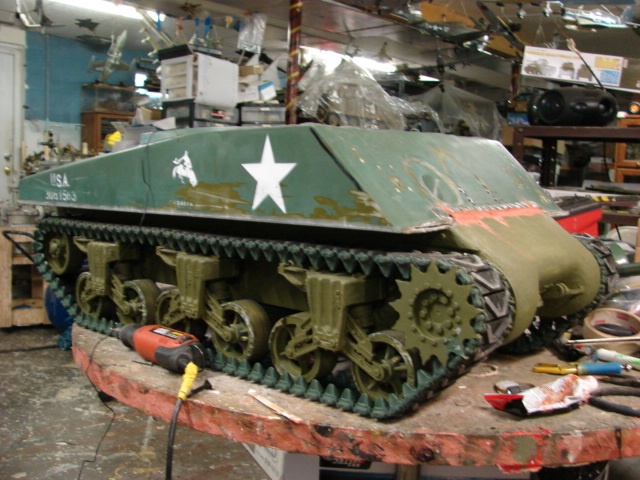
After completing most of the lower hull details I gave the lower hull a shot of primer and I applied it's preliminary base coat of OD. The rubber tires have been masked to protect them from any over spray.


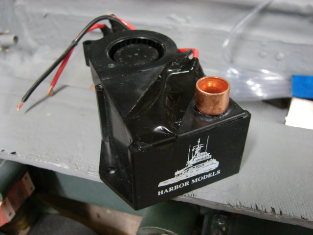
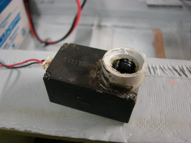
After the model was painted it was time to add the machinery. First I added the tank's smoke generators. For the main engine exhaust I used this smoke generator from harbormodels.com. I have used this system before in the King tiger and jagdpanther and I have no complaints on the system.


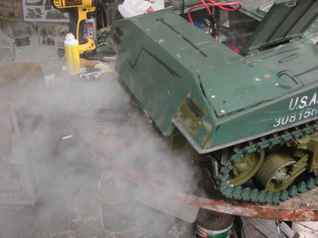
For the little Joe generator smoke I used this smaller smoke generator that I had on hand. This smaller generator emits less smoke, which is why I’m using it for this application.


As in my other RC tanks with smoke I build into the model it's own on board smoke fluid refilling pump system. To do this I use a small RC fuel pump.


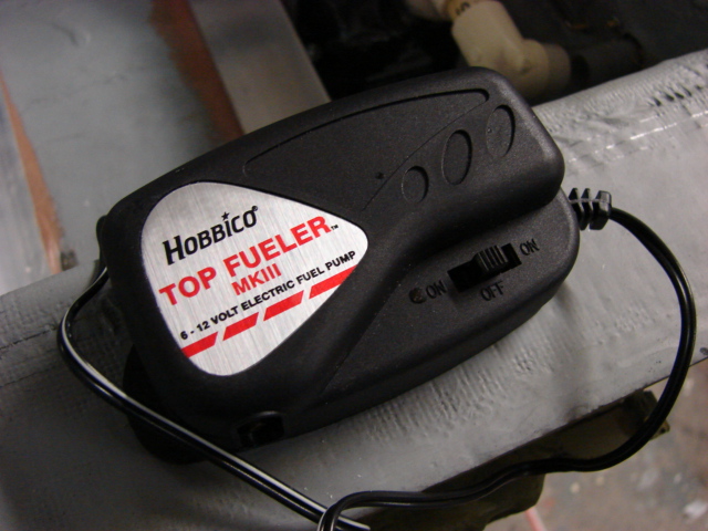
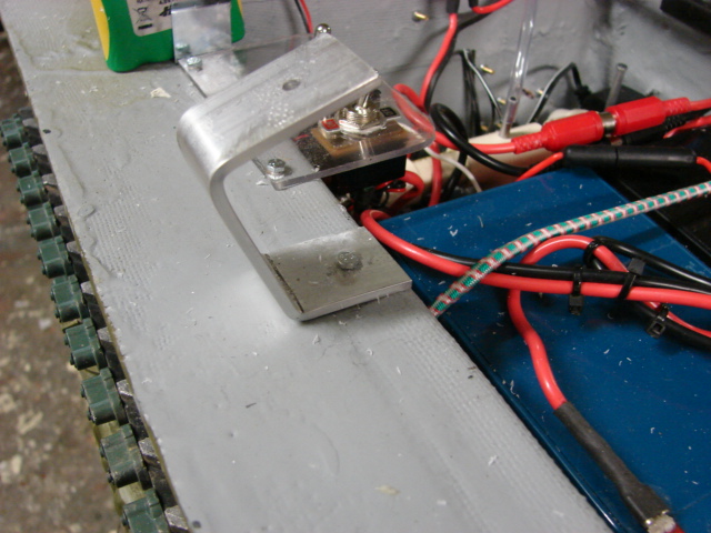
The pump refills the smoke fluid reservoir when they run low. To make the power switch more reachable I fabricated this handle out of an aluminum tube and a long bolt.


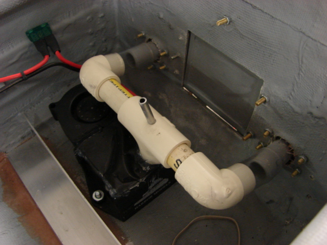
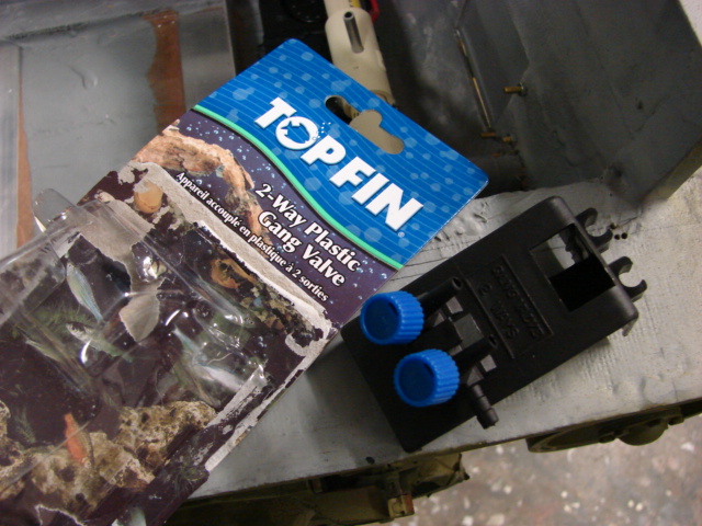
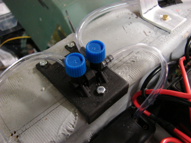
Since this model is equipped with two generators I needed to mount a valve system so I can control which generator gets refilled. To do this I mounted an aquarium gang valve to the model. With this I can refill both at one time or each of them individually.


All the refueling system needs to complete it is the refill hose. This is the hose that will extend out of the vehicle so I can refill the generators from a distance. This is done to minimize any chance of spilling the smoke fluid onto the model which can ruin the finish.


As for the smoke system I'm currently waiting for an electronic speed controller to arrive. Once it arrives I can complete the system so that it has proportional throttle smoke. The system will also be able to switch from main engine smoke to generator smoke as per the real vehicle.


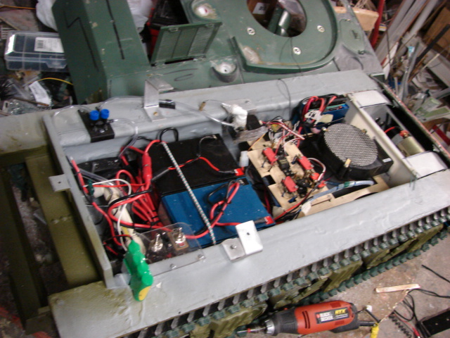
After the smoke system I concentrated on the rest of the tank's electronics. I relocated the tank's kit supplied servo tray to the center of the vehicle. I needed the back end to house the batteries so I can get easy access to them for recharging. The exposed turret rotation and gun elevation control servos will be encased in a plastic box to keep from getting snagged by any umbilical cord wiring that will enter into the turret.


The tank's gear box came with a dust cover. this cover completely covers up both the motors and the gears from the top and back . Before the addition of the sponsons you would need this feature, but with the addition of the sponson sealing up the lower hull the dust cover becomes redundant.


After driving the tank out doors I noticed that the motors get very hot. If you have them encased with the cover while driving the tank even without the sponsons I feel that the motors will over heat and possibly burn out.  

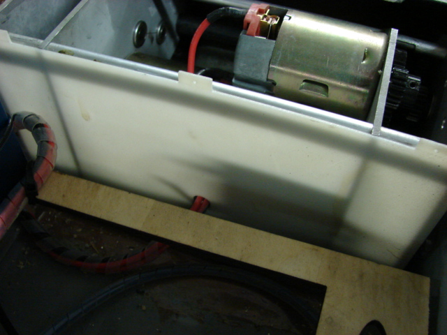
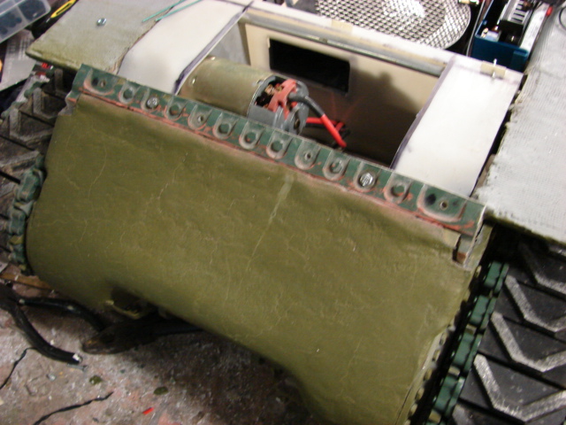
Even though the dust cover will no longer be needed to keep debris out of the gear box I decied to modify the cover to only cover the gear sections. I did this because when you lubricate the gears oil and grease will be flung all over the tank's interior. I also did this to prevent any wires or other matierals to be caught into the gears causing unwanted damage. To make the mod I simply cut out the center section of the top dust cover leaving the center with the motors exposed.


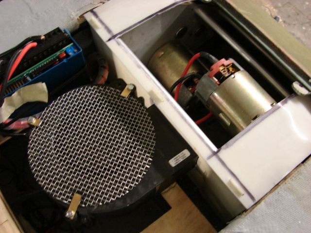
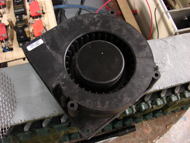
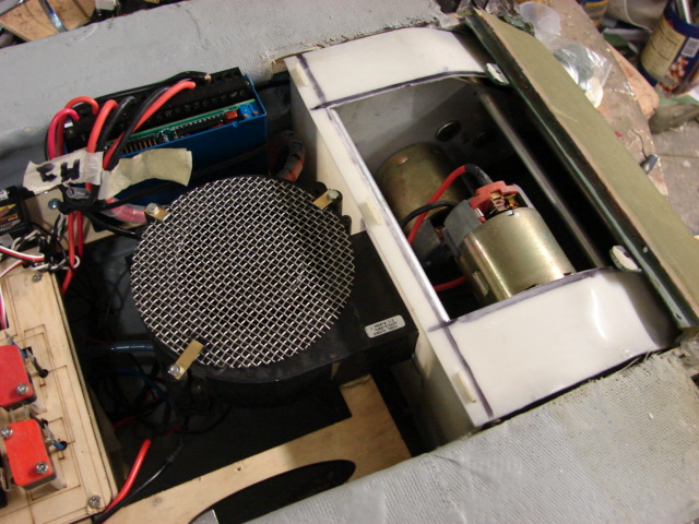
With the center removed the motors now have more air to breathe, and the gears are still protected. To cool the motors off further cut a hole in the rear portion of the dust cover and I mounted a large PC blower cooling fan.


The blower fan I also had lying around the shop


The 12volt fan was another component I had lying around the shop. It is very powerful and does exert alot of air 


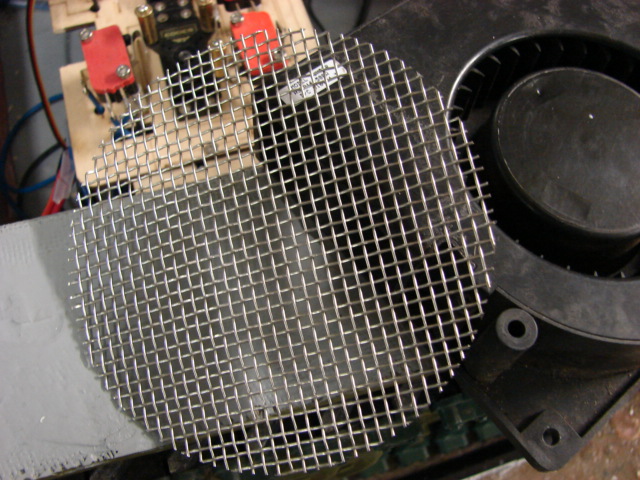
To protect the fan and to prevent any wires or other foreign material to fall inside I fabricated a fan guard out of a spare metal grill. The grill is actually a spare from the Armortek king tiger. Brass strips were soldered to the sides and the component was added.


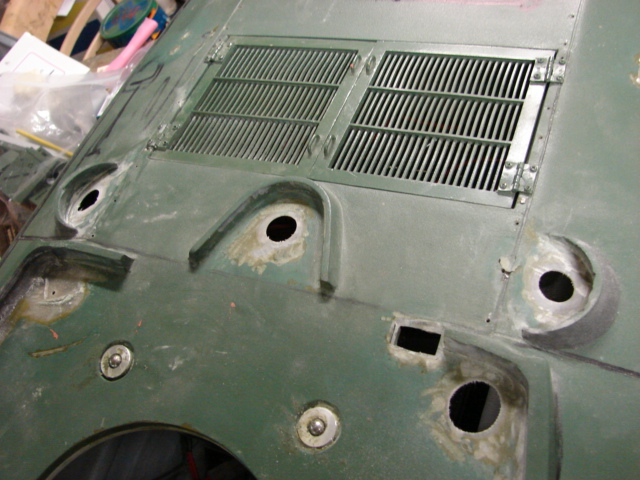
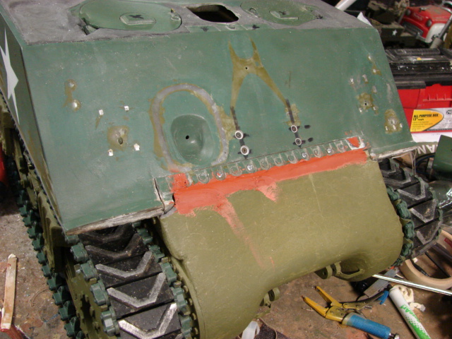
The last revision I was able to make to the model was the upper hull mounts. On the stock model the upper hull and lower hull were secured with three bolts. One in the center rear and two along the transmission cover. This system was simple, but not only hurt the look of the model, the rear portion still had some wobble to it. To correct this I redesigned the kit mounts. To mount the tank in the rear I decided to conceal the new bolts under the fuel caps. 


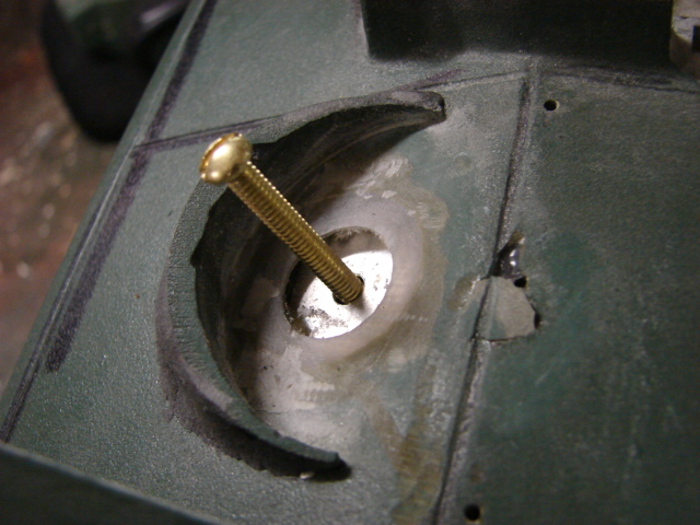
The molded in fuel caps were removed, and the holes were cleaned up. 


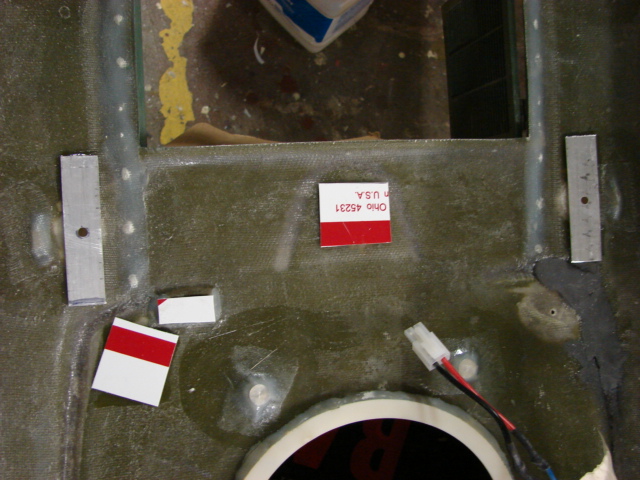
Aluminum strips were mounted to the hull and were fiberglassed into the upper hull shell.


for the lower hull I fabricated the mounts out of two bent strips of Aluminum . These mountes were bolted to the hull. 


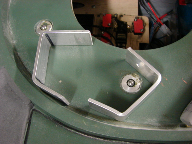
The new bolts simply bolt into these locations. This new design eliminates the wobble that was present with the kit design. As the build progresses I will be adding the functional fuel cap covers, and I will be reworking the bolt heads to look like the fuel filler caps so I can still display the fuel caps open. 


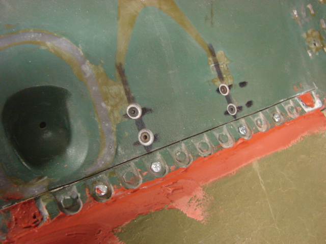
In an earlier post I had written that the transmission rivet strip was molded into the upper hull and that I was going to leave it and tolerate a small seam there the two hulls met. After much decision I decided that the seam was unacceptable and I decided to rework the transmission cover mounting further. 


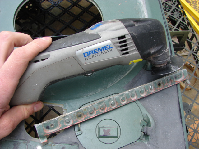
To make the alteration I had to first remove the molded in transmission strip and to permanently bolt and mount the strip to the tank. To remove the strip I used the Dremel multimax to perkily cut out the part. 


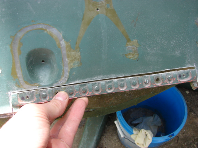
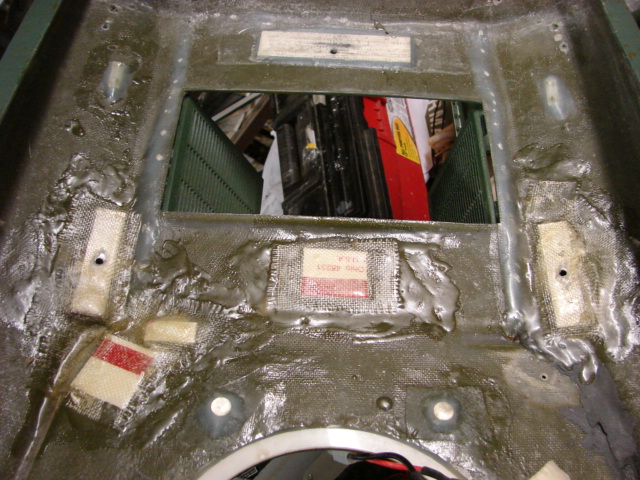
To mount the hull to the front transmission I mounted two aluminum strips to the front plate. These strips were mounted with counter sunk bolts. These bolts will be coved up with epoxy and body work leaving a smooth surface.


Now the front will mount to the transmission bolt strip using two bolts that are located on the bolt strip. With this design I can still remove the upper hull, but I will have no seam running along the transmission cover which on the real tank is a solid unit, rather I have moved the small seam to a location that is found on the actual vehicle.


I will now be focusing on adding the remaining electronics and functions. Once the electronics are complete I can then start on the detail aspect of the build which shouldn't take too long. More progress to come!  


  • Member since
    April 2005
Posted by armourguy on Sunday, May 15, 2011 1:14 PM

More progress has been made to the vehicle.


The last of the electronic components have arrived and have been added to the tank.


To complete the smoke function the new speed controller arrived from over seas. These speed controllers are very affordable, can handle high voltage, but only work in one direction.


for the smoke system controls I came up with a system that controls the speed controller’s potentiometer, and also switches the circuit which will turn off one smoke generator and activate the other one. 


I made a quick video of the smoke systems in operation and posted it up on youtube.

http://www.youtube.com/watch?v=4pLbMLqtiCA  


To finish up the remaining hull functions I am waiting on some parts from panzerwerks and for some of my new parts which are currently in molding. Once ready the hull will be complete RC wise. so more info will soon follow.


I then moved to detailing the upper hull. On the stock model the front hatch sections were flat and flush with the upper hull.


On the real M4A3 Sherman tanks the front hatch portions of the vehicle were made out of sections of cast steel which were then welded to the rest of the flat plate armored hull. These sections protruded from the rest of the hull. To replicate this feature I sculpted the cast armor sections over the kit hull with epoxy.


These sections have the smooth cast texture that was present on the real vehicle as well as elevated appearance. All that needs to be added to complete these sections are the cast numbers and the front antenna cover plate.


Along with the front hull section rework all of the upper hull weld beads have been added. All welds were sculpted out of epoxy on this model. 


After the welds I decided to rework the turret. After looking at the turret for a while I realized that the stock Vantex turret is too small. The turret has the correct width, but it is too short by about 3/8th of an inch. This is why the stock turret has a squat low appearance. 


In addition the turret is missing the extra casted in integral armor that was found on the gunner's section of the turret. This feature was only found on these late high bustle M4A3 75mm turrets.   


Fortunately these errors are NOT terminal and were resolved.


First to create the extra cheek armor I glued on several strips of sheet styrene. These strips build up the structure for the epoxy sculpt that will cover them later.   


To correct the turret height problem I first removed the stock air filter housing, removed the stock shell ejection hatch and sanded down the rest of the turret's top detailing. 


Once the turret's roof was sanded flush I then mounted a 3/8ths of an inch thick panel of plywood to the turret roof. The plywood plate was cut to the shape of the turret roof plate and had it's sides beveled. Holes were drilled into the plate for the hatches, periscope, and air filter. A 1/4 inch thick panel of plywood was also mounted to the rear turret bustle.


To raise the antenna well walls a small section of PVC pipe was added to the molded in well. The PVC pipe was the same diameter of the molded in version. 


After the panels were secured to the turret All wooden components were treated with fiberglass resin. After the treatment I reinstalled the air filter and other turret cast details. These would be the gunner's scope mount, copula gutter rib, and the replacement shell ejection hatch. Once the details were added the entire turret was encased in sculpted epoxy completing the size adjustment. 


The turret's cheek armor was also sculpted in at this time. 


The turret now has a better filled in look to it and propper silhouette than before. 


I added a coat of cast texture that enhances the turret's surface further. The turret is now ready for the turret details and cast numbers.


I will now be focusing on the tank's main gun and front glacis plate. More progress to follow this week.     

  • Member since
    April 2005
Posted by armourguy on Thursday, May 19, 2011 12:36 PM

A little more progress has been made to the model.


I have completed most of the front hull detailing, all that remains is the addition of the front metal fenders, the panzerwerk MG ball, and the side view mirrors.


I replaced the kit's molded in bow MG ball well with a new resin detail component. Here is a sneek peek of the new component.


Kit


replacement


The new resin version is a drop in replacement for the Bow MG well. The new well is compatible with the panzerwerk MG ball, and also features the interior detailing. On the real vehicle the MG well was a circular cast steel component that was welded to the front armored plate with two rows of welds. This MG well will work on any 1/6th scale late M4A3 (JD, Plastic Panzers, Panzerwerk...) The cast texture and the weld beads have been built into the resin version as well. I'm currently working on the last part for this upgrade. Once the last bit is complete the well will be added to the product line.


I also completed the tank's head light posts, These posts are also designed for the Late M4A3 (and will also work on the JD, Plastic Panzers, Panzerwerk...). The posts have been added to the product lines. http://www.eastcoastarmory.com/m4.htm


I was also able to mount the tank's head lights horn, and metal brush guards. The head light brush guard chain will be added later. I will be making the tank's head lights light up with LEDs. I also casted my blackout lights in a new clear resin so that they will be able to light up as well. I will have more info on the light soon.


The tank's functional travel lock was another component that was added.


I was also able to rework the tank's gun mantlet. I wanted to replace the kit mantlet with one of my resin versions.


The mantet is permanently attached to the rotor housing. To remove I had to cut the barrel extension severing the mantlet from the rotor housing. 


I then was able to wiggle the gun barrel free from the kit mantlet.


I reattached the gun barrel to the new mantlet and the rotor housing.


One mod that I needed to make to the elevation mechanism was I needed to move the elevation bolt closer to the spindle. With the bolt repositioned the gun will go up and down with the new mantlet with no snags.


I will now be focusing on the creation of more new detail parts. Once complete I will post another update. More progress to follow.   


  • Member since
    March 2006
Posted by TD4438 on Thursday, May 19, 2011 4:09 PM

Fascinating workmanship!

  • Member since
    September 2005
  • From: beacon falls , Ct.
Posted by treadwell on Thursday, May 19, 2011 6:43 PM

As always, very cool stuff... a little off topic, but I am trying to find your 'you tube' post on your KT with the animatronic figures... that was yours yes?

It is almost as though you just might as well shitcan the original tank and build it from scratch with your own company's stuff ... any how , VERY cool in my book.

best regards '

tread


  • Member since
    April 2005
Posted by armourguy on Saturday, May 28, 2011 12:44 PM

Thanks for the compliments, My King tiger model doesn't have the animatronic figures, you have my model confused with another armortek tiger. I have been working on the king tiger webpage which will contain more images and video clips, I have been working on the site during my spare time, which is not very much. I have filmed more videos of the king tiger running and I'll post on youtube soon.

I have made more progress to the model.


I completed the tank's hull lighting. The lights are hooked up to the RC equipment and can be activated remotely. For the lights I used LEDs. The head light and tail light lenses will be added after the model is painted.


To cool the motors further I mounted a small fan to the front air blower.


For the fan blower cover I fabricated a new replacement detail part out of resin.


I have also added the tank's VVSS track racks. Both The blower cover and the track racks have been added to the product line, http://www.eastcoastarmory.com/m4.htm. These new parts have also phased out the old metal versions that I had on the site. These newer resin versions are more affordable, better detailed, and is less time consuming to create than their older metal counterparts. On this RC model I casted the racks in flexible resin due to their location.


The tank's sheet metal fenders have been added, along with the side skirt and fender mounts.


While on the tank's front I added the functional tow cable lock and the functional comb wire cutting device.


On the tank's rear engine deck I have added the tool posts, functional fuel cap covers, lift hooks, tail light brush guards, fire extinguisher, armored air intake, drainage holes tow cable cleats, and the rear turret splash guard which was missing on the rear hull. I have also etched in all the panel lines that were not as visible in the upper hull casting and I added the engine deck fastener detail.


The upper hull is about 80% complete. I will now focus on completing the bow MG, folding rack, and revising the engine grills. More info to follow.


  • Member since
    April 2005
Posted by armourguy on Saturday, June 4, 2011 3:47 PM

I have made some more progress on the sherman.


I completed the tank's bow hatches. The model comes with the hatches pre installed. The Hathces are the correct size and shape and do open properly. The hatches do not come with any interior hatch detailing, and the molded in periscope detailing is too close to the hatch rim. 


To rework the hatches I first goround off the molded in periscope details.


I then fabricated the interior detailing out of sheet styrene and resin. I also added a set of interior resin periscopes from Panzerwerks.


On the hatch exterior I replaced the molded in periscopes with two of my won resin versions and I placed them more towards the center of the hatch. I also added a set of my brass periscope brush guards and I added the rigidity ribs to the hatch exteriors.   


On the tank's turret I replaced the air filter cover. On the air filter cover I added the rough cast texture. I will also be adding the cast and foundry numbers, but this will be done soon.


I added the loader's periscope. For the loader's periscope I made the scope pivot via a servo.


The tank's gunner's scope and gunner’s scope armored cover were added.


On the tank's rear wall I added the last of the tool posts, this one is for the engine crank.


I have also able to complete the tank's bow m1919 MG mount. For the MG and MG ball I used the pazerwerk resin version. I was able to make the MG pivot as well.


On the tank's rear deck I fabricated and added the engine hatch stops.


I was also able to build the folding rear rack. The rear rack has been retooled to make it more accurate than my last version. The new version is fully folding and has all of the restrain details.


All of these new items have now been listed to the product line http://www.eastcoastarmory.com/m4.htm. The new version of the rack has replaced the other version that I had listed on the product line.


I will now be focusing on the tank's turret. On the tank's hull I will be finishing off the engine grill revision, and the addition of the mirrors. The tank should be ready for paint by the end of this week.


I will be adding a you tube video of the new functions. this will be added soon. more to follow.  


  • Member since
    April 2005
Posted by armourguy on Wednesday, June 8, 2011 2:59 PM

I have added the last of the model's details, and the model is now ready for painting!


The tank's engine grills have been reworked. The original grill work was missing the interior detailing and had the wrong number of support beams.


To remove the grills I Used the multimax I removed the molded in grill work. and replaced them with new grills made out of soldered brass.


To complete the grill work I also added the air intakes. The intakes are also all fabricated out of sheet metal and was soldered to the brass grills. The engine hatches now have a more mass and a more heavy feel to them.


The reimander of the turret detailing has been installed aswell. 


These parts would include the 50.cal bustle racks, with functional barrel clamps,


loader's hatch,


Late war Commander's copula. To complete the copula I will need to add a panzerwerk periscope,  


The range finder, 50.cal travel lock, 50.cal pintle mount, and turret lift hooks. 


I was able to mount the tank's searchlight and the MP48 spring antenna base. The searchlight I made light up, and the MP48 is connected to the tank's radio receiver which extends the radio range.. 


I was also able to remount the turret and the main gun. to mount the gun the model originally use small Philips screws. These were replaced with slot screws, as they would be on the real vehicle. 


On the tank's lower hull I mounted the side view mirrors frames. A real glass mirror will be fitted to the frames after the tank is painted. the mirrors are fully pivot able and telescoping as they would be on the real vehicle. 


All of the tank's cast and foundry numbers have also been added. 


[img]http://eastcoastarmory.com/forumPic/vantex_sherman/ready_4_paint/DSC00080.JPG[/img]


The final addition and function that I have added to this vehicle is the M3 smoke mortar. On this model I decided to make the mortar full function and be able to launce real smoke charges. 


I added a video of all of the tank's functions, (including the mortar) in action up on youtube. 


http://youtu.be/JjrAzCmd2jI 


The tank will now go into painting. More to follow!


  • Member since
    April 2005
Posted by armourguy on Thursday, June 9, 2011 3:34 PM

Today I was able to take advantage of the 90 degree weather to apply the tank's final prime and base coat.


Final Prime


For the model's base coat I used the same shade of OD that I used on my M26 and DML jeep.


Now that the base is on the model can now get it's markings and then the weathering. More to follow.


  • Member since
    April 2005
Posted by armourguy on Friday, June 17, 2011 2:50 PM

After about a week of work the tank is now 99% complete.


After the tank's base coat I added the tank's markings. All markings are painted onto the model via stencils.


For the tank's rear engine hatch intakes I painted them primer red.


Once the markings were complete I then added the tank's weathering.


It was at this point where the tracks get reinstalled. The tracks themselves were also repainted and weathered.


Also on the chassis all road wheel zerk fittings and fire extinguisher handles were painted red.


All of the tank's pioneer tools and spare tracks have been built, painted, and mounted. All wooden tool handles are made from real wood that is treated and varnished.  


The tank's headlight and tail light lenses were added.


real glass mirrors were mounted into the rear view mirror mounts.


The bow and turret M1919 MG barrels was also mounted.


The tank's fuel caps have been added. The detail fuel cap head has also been mounted to the rear locking bolts concealing them. 


The ceramic insulator was painted on the MP-48 spring antenna base


All hatches are painted and their periscopes have been added. 


The cover caps for the searchlight and the 50.cal pintle mount were added. In addition all chain work has been added to the tank.


All the tank needs now to be fully completed is the gun cleaning kit, and the 50.cal MG. Once complete I can then give the shop a good cleaning and I can then start on my next project.  

  • Member since
    September 2005
  • From: beacon falls , Ct.
Posted by treadwell on Friday, June 17, 2011 3:56 PM

I love it man. I love the scale.  I love those freekin rear view mirrors !

great job

tread


  • Member since
    April 2005
Posted by armourguy on Tuesday, June 21, 2011 10:28 AM

Thanks Will, I added the last of the parts and the tank is just about complete now.


The tank's gun cleaning kit was built and painted. The cleaning kit actually screws together. Once completed the rack was mounted to the rack.


I have an armorpax 50.cal cradle on route. Until the mount gets here I borrowed a complete 50.cal and mount from one of my other shermans for some out door images.


I took some video clips of the sherman driving around. which I will post soon.


I will also be now working on the tank's gallery website. Once complete I will be staring on the next project.

  • Member since
    April 2005
Posted by armourguy on Monday, July 18, 2011 9:37 PM

It has been a while since I had any updates on the tank since I completed it, but I was able to install the last two components fully completing the tank and taking some more out door shots.  


For the tank's M2HB I again used the armorpax white metal cradle mount with the DML M2HB kit. The M2 received the same mods as I have done to these DML guns in the past. 


The mount was assembled and is fully functional.


After the mount was assembled the gun was mated.


The gun and mount were then painted and weathered.


Before I put the borrowed gun back onto the model it came from, I wanted a quick shot of the gun on the storage mount. When in storage pintle the barrel would be removed from the receiver and placed on the storage rails (not shown in the images).


In addition to the 50.cal I was also able to add the interior commanders periscope detail. The periscope is the Panzerwerk US periscope and was modified to fit the copula hatch.


With the tank fully completed I took some out door shots along with my Viper M4.


I have also uploaded a video of the completed model driving on youtube.

http://youtu.be/a7GNp2G1rYI


With the tank now complete I will be making the model's gallery webpage and will be posting more images once complete. More to come.


  • Member since
    April 2005
Posted by armourguy on Tuesday, August 23, 2011 1:31 PM

It's been awhile since I posted on this model, but I have just finished the tank's gallery webpage http://www.eastcoastarmory.com/vantexsherman/boogieman.htm .


On the webpage I have listed more images, and video clips of the tank. 


With this page out of the way I can now start on the Jumbo's gallery.  

JOIN OUR COMMUNITY!

Our community is FREE to join. To participate you must either login or register for an account.

SEARCH FORUMS
FREE NEWSLETTER
By signing up you may also receive reader surveys and occasional special offers. We do not sell, rent or trade our email lists. View our Privacy Policy.