Hi, Ken. Thanks! 
Inserted 6/4/19 from First Annual Berny Memorial Group Build, page 44.
The following is from some of my posts in Ken's First Berny Memorial build, plus some supplemental information about building the bomb bay and cutting out the upper bomb bay doors.
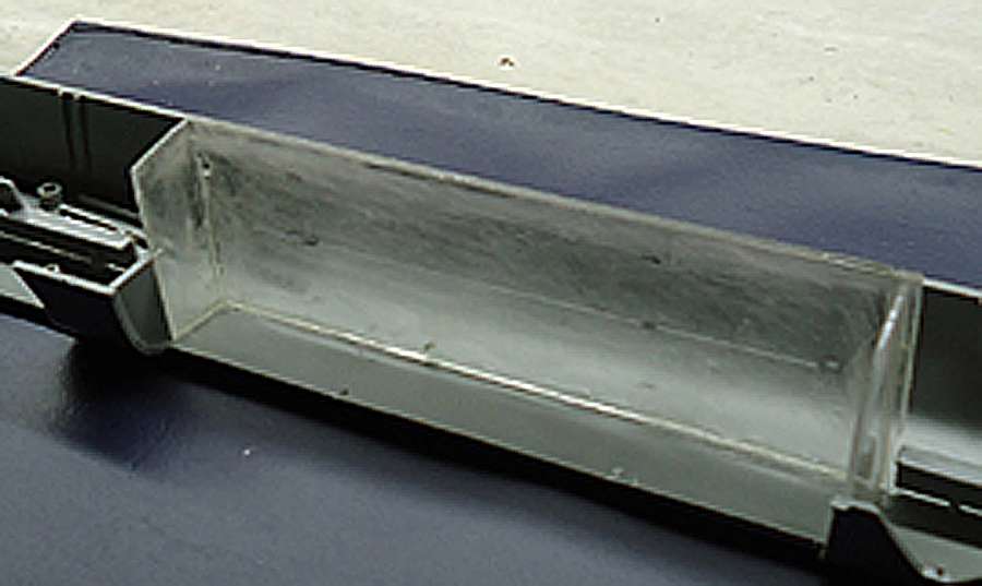
I built my bomb bay out of 1mm sheet plastic to fit into the right fuselage half, as shown below.
The dimensions for the internal structure are given in the diagram below. These dimensions are approximate and may need to be adjusted slightly for your installation. Test fit all parts before gluing the structure together. NOTE: You may have to trim some internal fuselage mounting points to fit the bulkheads.
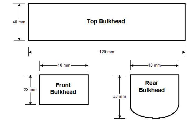
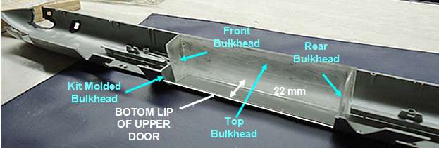
The kit comes with the lower curved part of the front bulkhead molded into the fuselage halves so you only need to add a top piece (Front Bulkhead in the image above) to complete the front bulkhead. Also, use this bottom bulkhead to shape the bottom of the Rear Bulkhead.
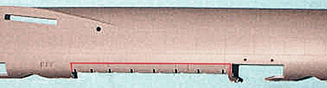
If you want to show the bomb bay doors opened to the load position, you will need to cut out the upper bomb bay doors. These are clearly outlined on the fuselage, as shown below. Use a sharp Xacto knife blade and cut carefully and repeatedly until the doors are separated.
Updated 8/4/19
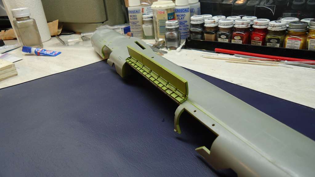
Adding the Catwalks
There were walkways (catwalks) on either side just above the lip of the bomb bay. These were part of a pathway that allowed you to crawl/crouch/stagger all the way from the cockpit to the tail gunner's compartment.
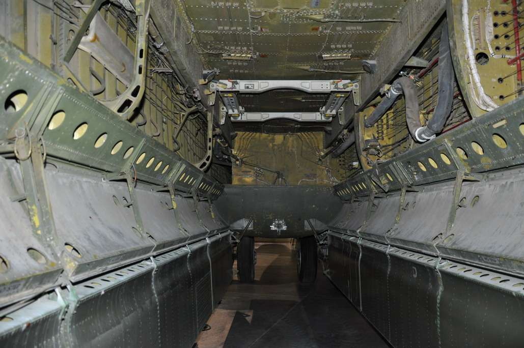
They definitely add interest to the model, so if you would like to add these, follow the procedure below.
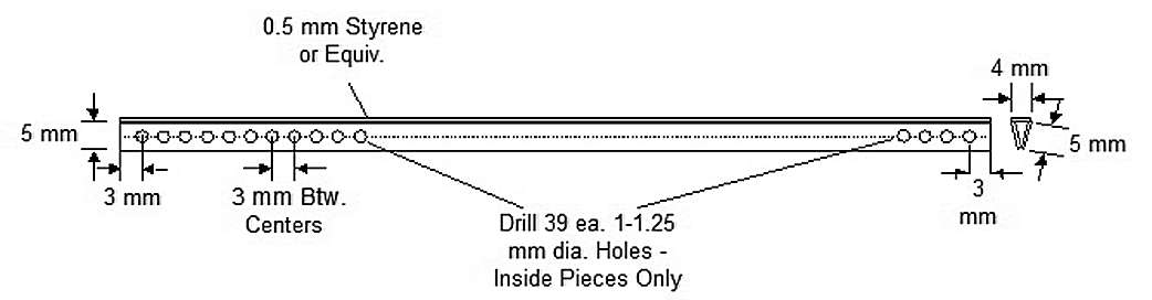
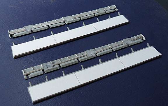
1.) Using 0.5 mm Styrene stock or equivalent, cut out four strips 120mm long by 5 mm wide, and two strips 120 mm long by 4 mm wide.
2.) Select two of the 120 x 5 mm strips and mark a line down the center of each.
3.) Starting from either end, mark off 39 points 3 mm apart along the center line.
4.) Using a 1-1.25 mm drill bit, drill 39 holes centered on the marked center line points.
5.) Glue one 5 mm wide strip with holes and one 5 mm wide strip without holes to form a "V", as shown in the diagram below.
6.) Glue a 4 mm wide strip along the open top of the "V". This forms the catwalk "deck."
7.) Assemble the second catwalk per the above steps.
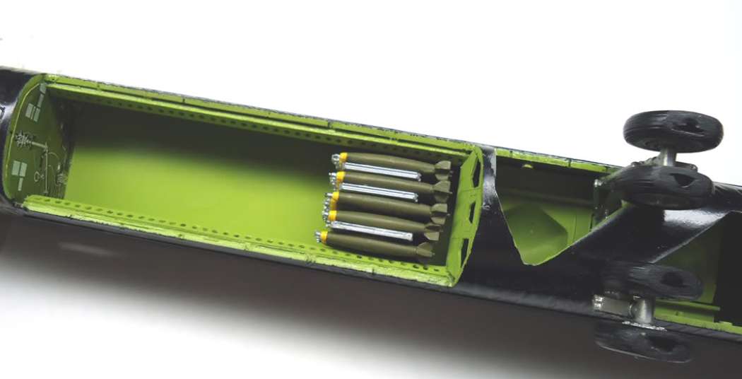
8.) Glue the catwalks to the inside lip of the bomb bay, as shown in the pictures below. NOTE: Be sure the sides with the holes faces inward.
Detailing and Attaching the Bomb Bay Doors
I added some card stock and styrene strip detail to the doors, as shown below. Note that this only "suggests" the actual detail; it's not accurate.
Mounting the Doors
At this point, you're faced with two choices for mounting the doors to the fuselage:
A) Glue the top edges of the upper doors directly to the fuselage, which is a messy way to do it and there's no guarantee the doors will stay in place, or
B) provide some kind of attaching system that also supports the doors. The method I used is described below.
You will need some ordinary office staples for this task. Refer to the diagram below (NOTE: The photo shows my doors already assembled at this point, but mounting the upper doors to the fuselage first before attaching the lower doors will save you a lot of grief.)
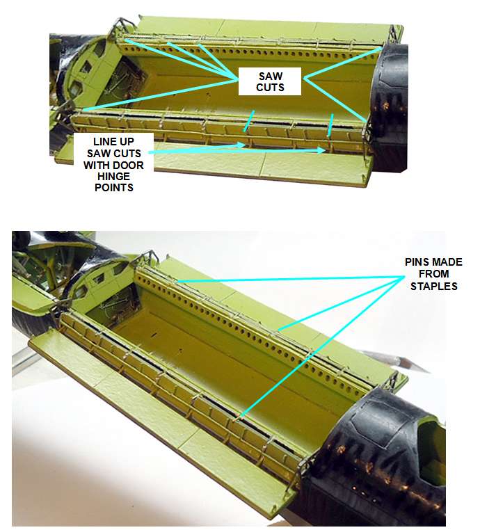
1) There are 8 hinge points on the bottom edge of the upper door where the lower door hinges to it. Use these as a reference and with a razor saw, make shallow cuts about 1 mm deep across the top edge of each upper door, corresponding to the hinge points, as shown below.
2) Temporarily position each upper door in place and mark 8 points on the edge of the bomb bay corresponding to the saw cuts in the doors.
3) Make shallow saw cuts in the edges of the bomb bay at each mark.
4) Straighten and cut off lengths of staples to bridge across the slots in the bomb bay sides and the upper doors.
5) Position the first upper door so the top edge is even with the edge of the bomb bay and the slots line up.
6) Glue a piece of staple into each slot.
7) Attach the other upper door assembly in the same manner.
Once the upper doors are attached to the fuselage, attach each lower door to the upper door so that they are at a 90 degree angle to the upper door, as shown below. NOTE: I suggest you use rubber or tacky glue first to get the doors at the right angle before gluing them permanently.