SEARCH FINESCALE.COM

Enter keywords or a search phrase below:

Edward Hopper: House by the Railroad in 1:48 (start to finish)

20254 views
148 replies
1 rating 2 rating 3 rating 4 rating 5 rating
  • Member since
    March 2012
  • From: Louisville, KY
Posted by Builder 2010 on Friday, November 13, 2020 9:44 AM

Nope. Either paintings or the convex mirror. I'm going to have to put wall paper on them and have to print more of it. I also thought of painting that protrusion, but wall paper seems to be winning out. Some of those doodads are going onto the mantel too.

But... now that you mention it, I could print some animal heads. Anything is possible.

  • Member since
    October 2019
  • From: New Braunfels, Texas
Posted by Tanker-Builder on Friday, November 13, 2020 10:09 AM

 How about this?

      A very neat 1/12500 Sailing Ship?

  • Member since
    March 2012
  • From: Louisville, KY
Posted by Builder 2010 on Friday, November 13, 2020 5:59 PM

Visited the hobby shop today and picked up some of what's needed to finish this project. Then went to Michael's Crafts to get the rest. I needed more heavyweight Bristol Board, and some more 1/8" foam core. My building bases are a laminate of 1/8" Masonite and 1/8" foam core. This builds the base up to be one curb height over the green foam board that makes up the village streets. The Masonite's on top to give a more robust work surface for decoration, ground cover, etc. It also provides a stronge surface into which to implant utility poles, signage and fence posts.

Here are the finished beds ready to go into the bedrooms.

I got the place settings painted and attached to the dining table. My wife cracks me up. Her only comment was, "You're serving coffee and wine at the same time?" I explained that the setting that I downloaded looked like that. I know... lame...

Rather than fret about the missing silverware, I just took the Molotow pen and drew them in. You're not going to see it since you're viewing the table from the side. 

Here's the stuff onto the dining table. Two views.

I conveys what I wanted it to convey.

I cleaned up the paint job on the kitchen and put a backsplash on the wall with PSA. Nothing's glued in yet.

I put the casing around the window I started yesterday and started brush painting the fireplaces. I toyed with airbrushing them, but it would have created alot of masking. This was with two coats of gloss white. On Monday, I'll give it two more. I also touched up the trim. This image was taken with the 2nd floor in place so you can see lots of reflections off that glossy white ceiling. When the lights are on, it will look totally different. I can't wait.

I did reprint more wall paper for the fireplace fronts. It's why I started painting them now so I didn't have to worry about getting paint on the new paper. I painted those 1/4" square blocks in the corners to make them look like some kind of architectural detail. I does look better than raw wood.

Everyone have a nice, socially distant, weekend.

  • Member since
    March 2012
  • From: Louisville, KY
Posted by Builder 2010 on Tuesday, November 17, 2020 10:30 AM

Short time yesterday, but work continued on the interior side walls. Got the Living Room first floor side completed. And I did put some artwork over the fireplace. Just noticed that the trim is short on that far right window casing. Oh well... I may have to reprint the smaller casing and I can redo that... or not. Since it's so far over it may not be visible.

Got a good start on completing side two (dining and kitchen).

For the second floor windows I may go less elegantly. I'm thinking that those windows should be obscured by drapes and/or shades so very little will be seen. I may put the wall paper directly on the outer surface and not spend the time to pack it all out so the window casing overlap the window frames like I'm doing on the first floor.

Based on a suggestion on the Elegoo Mars Facebook Group I downloaded and tried using the PrusaSlicer, a free product that is more comprehensive than ChiTuBox which is included with the Mars and must be used to feed the Machine. While PrusaSlicer may be more elegant, I was dubious about the support array in the auto setting. It looked insubstantial for such a massive object. BTW: I redrew the kitchen unit to solve some of the problems with the previous print (warpage, detail obliterataion).

The processs to use the PrusaSlicer with the Mars is two-step. First, you import the STL file into PrusaSlicer and let it set up the supports. Second, you export this supported part as another STL file into the ChiTuBox to slice for the Mars. Here's how the imported STL looked sitting on the Mars slicer.

Like I said, this scheme seeme a little light. And it most certainly was. This is what greeted me this morning.

Total BUST! And will require a significant clean up to remove the cured blob that most certainly is stuck to the FEP. That EPAX film is getting a bit tired anyway so it will give me an excuse to replace it. Since I already printed this part successfully using the ChiTuBox support setting, I know the part is printable, so I'm now concerned about PrusaSlicer. Like ChiTuBox, Prusa has a lot of customization (even more) so I could have added more supports. Next time, I'll use my intuition and my 1.5 years of printing experience. If it looks skimpy, it probably is. Considering how long the supports are, the part may have broken free later in the print when more mass was hanging on the supports.

  • Member since
    March 2012
  • From: Louisville, KY
Posted by Builder 2010 on Tuesday, November 17, 2020 6:25 PM

With another shortened work session (haircut day), I finished up the dining/kitchen wall, and mounted the kitchen units into the first floor. I put the convex mirror over the fireplace, but noticed it's slightly off center. Hard to tell when the walls are in place, but I see it.

Then I noticed something bad. The 2nd floor ledge on the back wall was 1/8" below the ledge on the left side wall. I then made a bad decision... kindof like those kids in the Geico commercial when they decided to hide behind the chain saws. I thought I had glued on this ledge on the wrong side of the line I drew to denote the floor line. And then I went at hacking it off which then caused the side wall to split. This is entirely due to PVA glued joints often being stronger than the substrate to which they're glued.

Here's where that line is.

And here's the split side.

The only problem with all this and why my decision was so premature is the floor ledge in error was NOT that back wall. It was the left wall that I had just completed. I glued that ledge on the wrong side of the datum line. After checking the other two sides they concurred with the rear wall. Now I have to remove all that molding, the wall coverings and attempt to reposition that ledge... UGH. And then I see this.

The dining partition wall is horribly out of square. Part of this will be corrected when the ceiling height is reduced when I fix the floor ledge, but the wall is still terrible. Light will leak badly. Right now I have no additional lighting in the kitchen. I may have to add that since the kitchen is now a decorated space.

This was definitely a two-steps forward and one back kind of day. Those floor ledges were installed way back in the beginning of the project and now I'm paying for a simple error, forgetting which side of the line was the correct side. I was wondering why the open wall below those 2nd floor windows was so narrow. Now I know.

It will all work out in the end. The split wall is an easy fix. Clapboard is weak because the wall thickness is greatly reduced at the bottom of the board milling. It's just annoying. And I didn't start pulling the printer apart to replace the FEP. That can wait since I've nothing to print right now.

  • Member since
    March 2012
  • From: Louisville, KY
Posted by Builder 2010 on Wednesday, November 18, 2020 6:54 PM

Woke up this morning thinking about attacking this problem. You can tell I'm living in a low stress environment when the only thing I worry about when arising is how to fix an error in my House project. I decided to go right at it.

I was more judicious in using my Xacto so I didn't damage the exterior wall. I was able to cut the wall paper, Bristol Board, styrene strips and then removed the 1/8" square ledger board. I removed the 1/8" and lowered the board so if conicided with the other three walls. The project was looking a rehab on "This Old House", in the "demo stage".

Actually, it was sort of fortuitous that this error happened since putting all the crown molding on this wall as I had done, was not correct. It would have been interrupted by the dining room partition wall. When I repositioned the crown molding I correctly mitered it at the corner intersecting with this partition. Then I examined the partition-side wall intersection and found that I hadn't provided correctly for that either. The partition was not nesting against the side wall since it was being pushed off by the wall packing and covering, plus the crown moldings weren't shaped correctly. I needed to do more surgery to get it all correct. This image shows how the wall (buried deep in the image) now connects to the side wall. Without fixing this, it would have pushed the exterior wall out of plumb and would have created joint problems at the top of the wall.

Then there was that out-of-square partitiion itself. Instead of ripping it out and making it again, I just shimmed and sanded a filler to close the gap. Here was the gap that needed attention.

The fix require stripping the paper and crown molding from the dining room side and the crown molding from the kitchen side. The fix worked. The good thing about using the MicroMark Pressure Sensitve Adhesive is that it's strippable. I was able to peel the paper off without too much hassle and it's still sticky enough to attach the new paper.

I got all this back together and then... finally... got back to putting on the rest of the window wall paneling. The middle space will not have any real observable space and is where the wiring harness from the upper floors will pass through. The right side is the back living room wall. The four windows are been in position to hold the wall evenly off the work surface since one window is needed to be in place to position the spacers.

The last thing I did was add another LED for the kitchen. And of course this got a little more complicated. When I added the 4th LED in the same series circuit, the lights were way too dim. I needed to add a third parallel circuit with its own CL2 driver. Again, the PSA allowed me to peel the entire white ceiling covering add all the circuitry and stick it all back on with a little help from med CA in edges.

The kitchen is now lit... and brightly so.

Tomorrow is a full shop day. Since I promised my wife that I would work out on the recumbent bike and elliptical every other day instead of every three, it does cut into modeling time a bit, but I'm able to do both. The 65 minutes on the equipment is helpful.

I'm really itching to get the new iPhone 12 Pro especially for the cameras. I'm taking well over 1,000 pictures a year with all the project documentation I'm doing. I average around 400 images per project and usually get about 3 done per year. In reviewing the camera capbility of the 12 Pro I think it could help me a lot. I like that it can do good night and low light photography since some of the best images of the model railroad are when the room lights are out, but the iPhone 7 doesn't do well in low light.

If any one has any opinions on the subject, I open to suggestions.

  • Member since
    November 2009
  • From: SW Virginia
Posted by Gamera on Thursday, November 19, 2020 1:23 PM

Sorry, been away since I'm on vacation and the motel wi-fi does not like picture heavy threads with lots of ads like this one.

Weird about the floors being of whack like that but looks like you've got control of the situation now. Nice work!!!

"I dream in fire but work in clay." -Arthur Machen


  • Member since
    March 2012
  • From: Louisville, KY
Posted by Builder 2010 on Thursday, November 19, 2020 6:46 PM

Welcome back! I'm on a perpetual vacation. That's what retirement is. Vacation is just changing venues, which now is not so easy.

I've done about as much of the interior as I want to do. I've skimped on the bedrooms since I'm going to use window treatments to restrict the view. My addition of all this trim has made the original scheme—inserting the 2nd Floor from the top after the walls are all joined—not so doable. The various baseboards form locking grooves that need to have the floor inserted from the side, not from the top. So the floors will be glued into one set of sides and the other brought into alignment with it.

I finished putting the wall covering on the upstairs and did some final fitting of the 2nd floor to all sides. There was some minor trimming of some of the wall panels to permit the edges to mate properly mate. I didn't proceed with the mating at this time. It's too big of a step to rush into and I want to make sure I've got the process down pat. There's the question of when and how to install all the furnishing. It would be best to do it when the floors are not attached.

No window molding is on the 2nd floor and I ran out of the window casing and didn't want to print another batch. I do have a lazy streak...

Instead of charging ahead, I started to build the foundation. It's essential that the foundation and the main building work together so now was the time to do it. I'm using 3/16" X 1" balsa for the frame, with Chooch flexible cut stone wall on top. I'm going to repaint all the stones since I've already used there basic color scheme on the Appliance store.

They've modified their process for attaching this product. Instead of self-adhesive being on the back of the stone, they've included a sheet of transfer adhesive which has backing paper on both sides. You peel off the first backing and stick it to the substrate, then you peel off the other backing leaving the adhesive attached to the surface ready for the stone. I had to splice stones together since the stone sheet wasn't quite big enough to do all four sides. The stones are random, but I found enough facing one another to notch them and make the splice inconspicuous. I will do some crafting at the corners to make the stones appear more realistic.

I have a picture frame clamps that was my dad's and must be 70 years old which is helpful in gluing things like this. I used Aleen's and then thin CA to cure it quickly and let's me keep moving while the Aleen's slowly dries. 

The last thing I did was create a paper pipe to carry the upper stories to the basement. I didn't have any existing tubing of sufficient size to do the job so I rolled up some HP photo paper glued together with med CA. It took a couple of tries to get it of the right diameter right. It's not glued in, but will be when the floors are installed in the building. This back room will not be visible. The windows in the back door are simply too small to provide a view, plus there will no lighting.

  • Member since
    March 2012
  • From: Louisville, KY
Posted by Builder 2010 on Friday, November 20, 2020 5:59 PM

On a digression, I found out today that my Typhoon Model is featured in the "Reader's Gallery" in FSM's Jan 2021 issue. I found out from Brian Bunger (proprietor of Scale Reproductions Inc. - one of the finest hobby shops in the USA) via Facebook. We're members of the Military Modelers Club of Louisville which Brian was a co-founder 40 odd years ago.

Before completing the foundation I wanted to make sure the porch worked with it. I made a field change that caused me some hours of rework. In the original design I had the porch so scale feet below the front door, as shown in the orginal plan. The arrows show the offset.

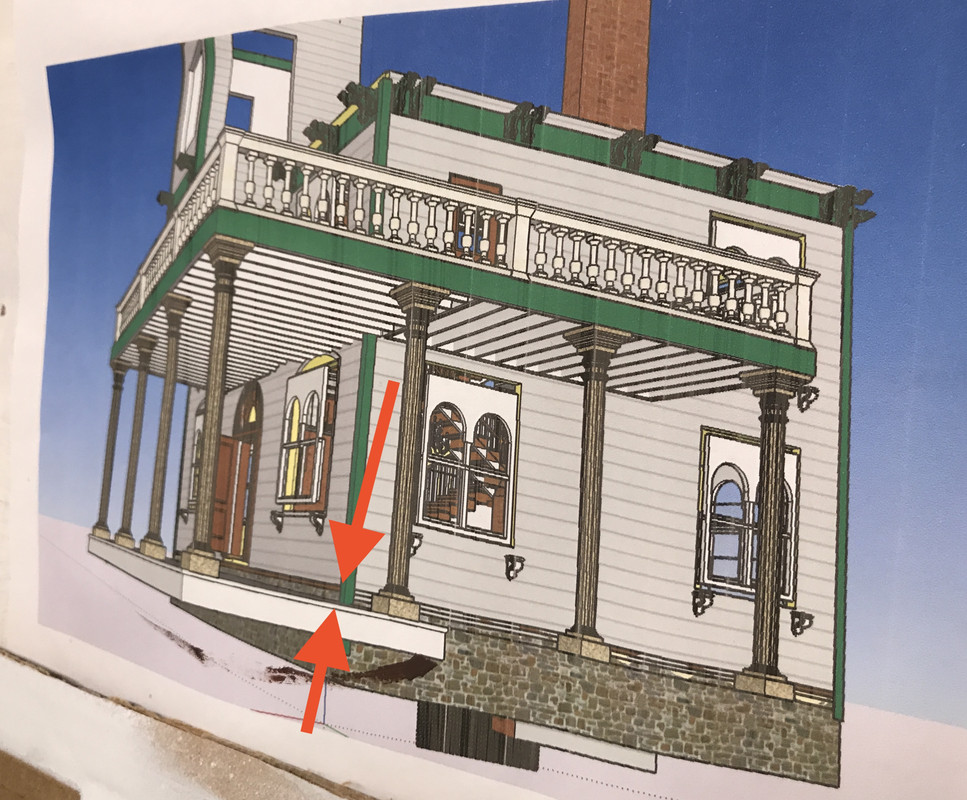
But when I put the porch blank next to the wall, it lined up perfectly ON TOP of the stone wall ledge and was flush with the front door sill and I liked how it looked. I was able to make some spacer blocks exactly the same 1" height of the foundation and glued them on to the bottom.

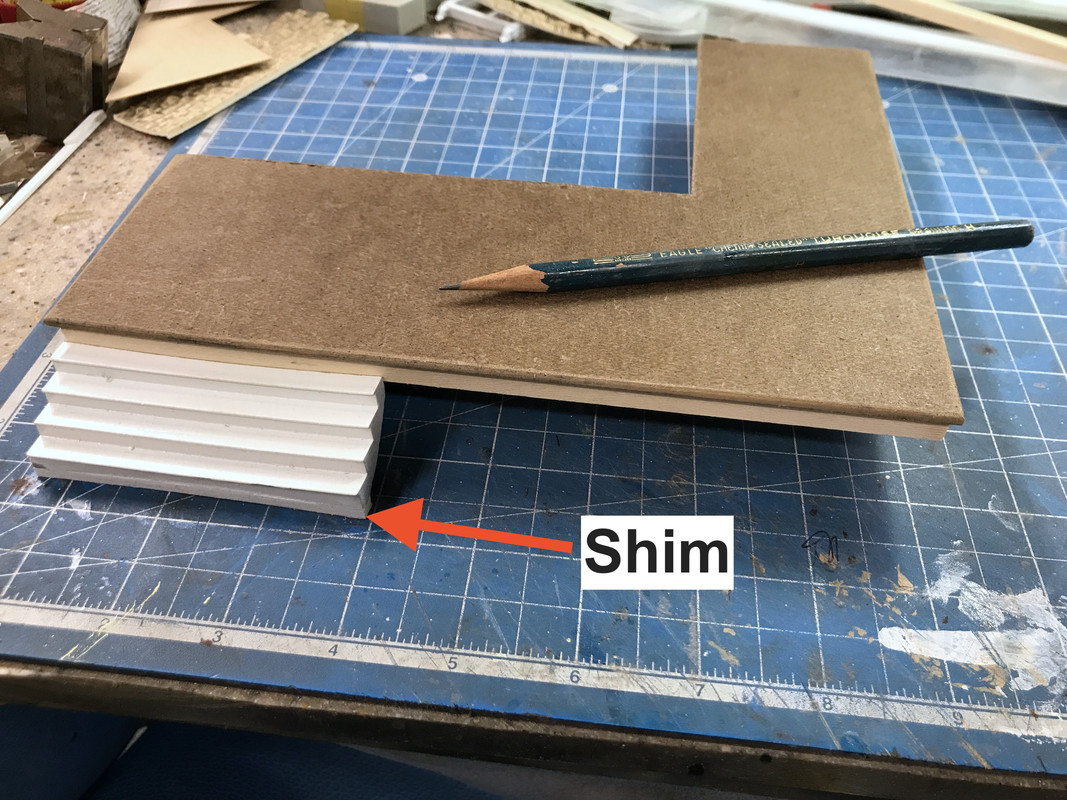
As usual with my "field changes" they had some unintended consequences. The steps needed some shimming so they would mate with the band boards under the porch. Since the steps were so warped I sanded the bottom of the first step and the back of the top step so they would mate with their respective surfaces. I used the big 4" belt sander to do this. I then added .120" of shim to bring the steps up to the right height.

And the columns were now too darn long. 

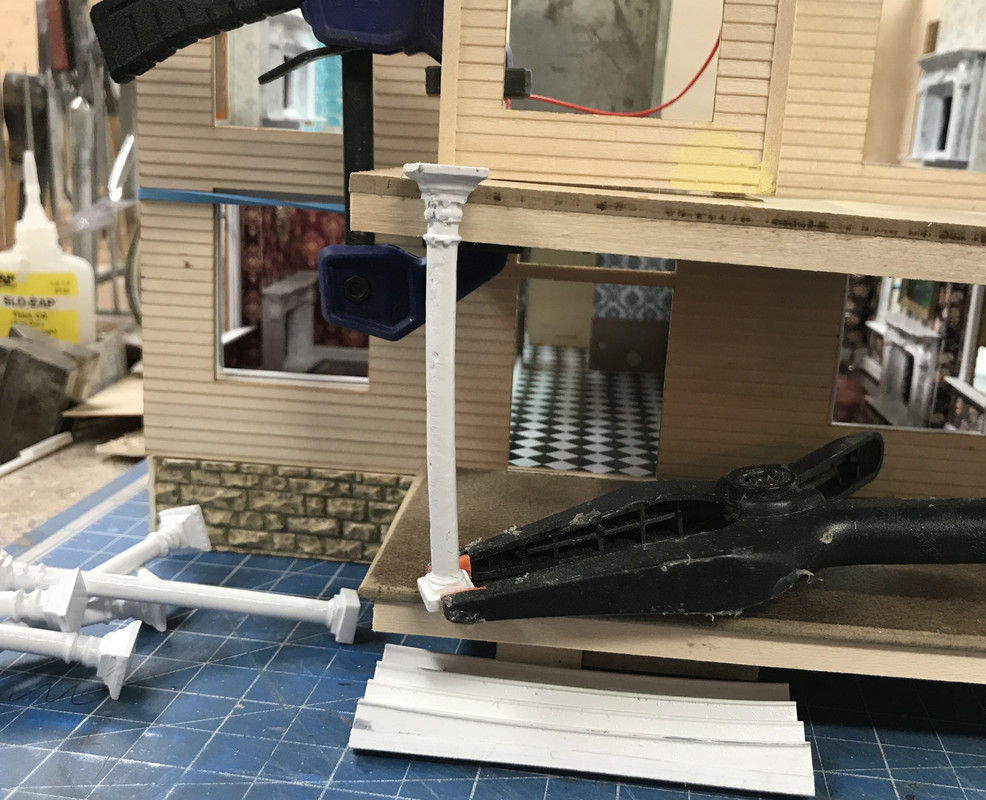
They were really long! I had two choices: cut the columns or re-draw and re-print them. The original prints didn't come out so good. They warped badly, had supports in strategic spots that made for a ragged cleanup. Cutting and splicing the columns looked doable. I held the building together with a big rubber band capturing the first floor plate and then clamped the balcony to its position snug up against the turret first floor and measured the distance. It came out to 2.63". The columns measured an average of 3.10". I did the simple subtraction and of course got it wrong. Instead of .47" I used .57" and wondered why they were so short.

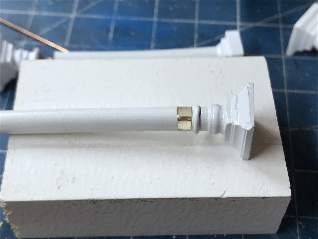
At the cuts I drilled for 1/32" phos-bronze wire. The wire let me pull out the column to get it too fit properly.

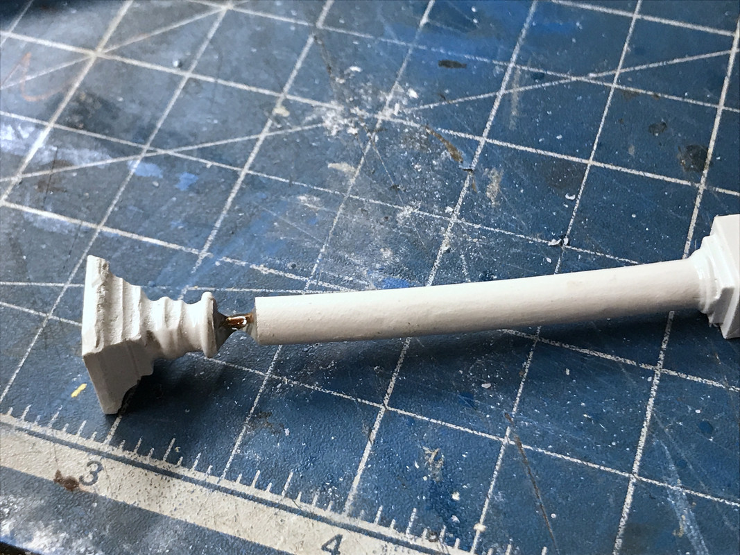
In the above I started filling the gap with Bondic. After a couple of these, I realized my stupid math error and removed the correct amount of stock on the remainder. As it is, Bondic and resin printed parts are a marriage made in heaven. Since it's the same compound, it not only serves as a good filler, it's also one heck of a glue. When I finished all the splices, the columns are solid. Furthermore, I was able to correct some of the more eggregious warps, by reconnecting them in a more straight orientation, adding more Bondic around the perimeter and then removing the excess with the belt sander.

After belt sanding I used my round object sander (don't have a better name for it) to finish them off.

In this case, the column snapped when I tried to rebend the warp. I took the .47" out of the middle where the warp was the worse. It will look acceptable after painting.

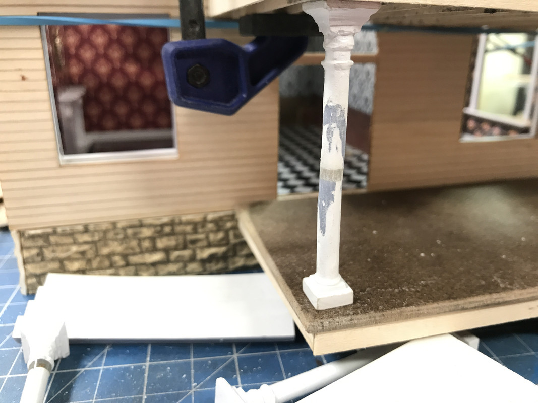
After all the mods were complete I tried them all out in their positions. This approach took some more time than reprinting would, but maybe not so much since I would have to modify the drawings, re-slice them, print them and then clean them up and paint. If they weren't resin, the Bondic solution would not have been so elegant.

I needed to scribe the porch to simulate some wood planking. I toyed with planking with real wood slats, but it would have raised the height above the door sill. Since I had already glued all the blocks underneath, removing the 1/32" of height so I could plank it would have been a pain. Instead, I'm scribing the planks. Porch will be painted so I just need the hint of planks underneath.

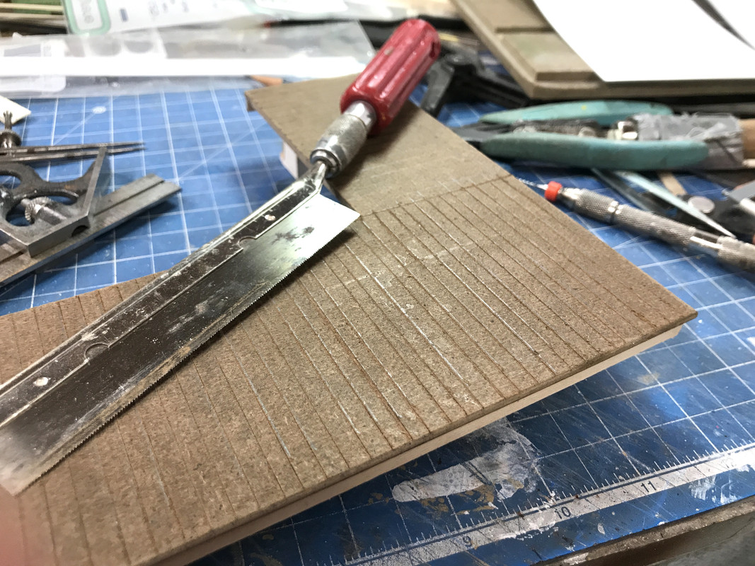
I measured off the planks about 10 scale inches. I used my Starrett machinist dividers. they hold their size setting very well. I used a machinist square and marked the lines with pencil.

I then used a razor saw and the square to actually cut the groove. Scribing Masonite doesn't work so well since the surface is friable and leaves a messy groove. Actually cutting the grooves works better.

I'll finish this up on Monday. As I've said time and time again, my weeks go by so fast that I'm shocked when it's Friday again. I wish they would have past so quickly when I was working.

I reckon it's becuase of this. First, I no longer get up at 6:15, commute anyhwere between 45 minutes to over an hour to get to an office, and not leave the office until 6 p.m. and have another massive commute. Regardless of where I worked in my career, my commutes were never easy.

Now I get up when I want, usually between 8 and 9, have breakfast, read all the crap on the laptop, take care of business and get to the shop between 1 and 2 depending on whether it's an exercise day. And then I quit by house rules at no later than 5 p.m. So instead of a tiring 12 hour work day, I'm spending an enjoyable 2 to 4 hour day in the shop building cool stuff. And that's why time is going so fast.

Have a great weekend and don't do anything stupid.

  • Member since
    March 2012
  • From: Louisville, KY
Posted by Builder 2010 on Saturday, November 21, 2020 5:31 PM

Well folks, here's a rare Saturday progress report. It was a nasty, cold and rainy day, and my darling wife asked, "would I like to play in the basement?" Of course the answer was a resounding "YES". And play I did.

The day was a "painting day". It started out noticing that the Chooch transfer adhesive was not holding the rubber stone sheeting. I ended up going around and using judicious applications of med CA to secure it all around. The adhesive was holding to the balsa well, but was not holding the stone. That surprised me. You'd think that the adhesive included with the flexible stone would at least work with that product.

I cut, trimmed the corners and filled any gaps with Bondic and then airbrushed medium gray for the stone base coat. On Monday, I'll go back and do some more work on the stones drybrushing highlight colors and doing more with the mortar lines.

Before installing the windows in the turret it had to be painted. Before painting I added some 1/16" square bass wood around the upper perimeter of the intermediate roof to act as the rain gutter stop. I then painted the clapboard with craft paint "Vanilla" a nice off-white color. I then painted the actual roof area Tamiya Nato Black, and finally the trim with a medium blue from Vallejo. So for this little structure I used three different kinds of paint. The blue is very close to the color I selected within SketchUp. I debated whether or not to paint the corner trim blue or wall color. Blue won. Again, it's the way I've displayed it in SU and I'm familiar with it.

Last thing I did was paint the chimneys. I thought that the gray base color would work for the mortar so I just dry-brushed the brick color (Vallejo Dark Flesh). Didn't quite work as I planned and the color filled in some of the mortar lines. I did paint the upper parts with concrete color for the cap base, a lightened brick color (yellow added) for the terra-cotta flue stack, flat black inside the flue and then added black powder for the soot.

I also put the base coat on the porch. This time I used tube medium gray artist's acrylic paint, so that makes four types of paint. After it fully cures, I'll see what else I should do, maybe some panel line accenting, or not. I also may sand the paint to expose base Masonite to show some strategic wear. The saw-cut scoring worked for the planks.

So like I said "it was a painting Saturday". I like working on occasional Saturdays. Have a nice Sunday!

  • Member since
    April 2004
Posted by Jon_a_its on Sunday, November 22, 2020 2:15 AM

superb work, as ever.

Isn't there a phrase about learning more from your mistakes?

Because it is very useful raeding about your recovery from them. I look forward to seeing the finished article.

East Mids Model Club 32nd Annual Show 2nd April 2023

 http://www.eastmidsmodelclub.co.uk/

Don't feed the CM!


  • Member since
    March 2012
  • From: Louisville, KY
Posted by Builder 2010 on Sunday, November 22, 2020 3:05 PM
It's why I'm so "smart". I make a LOT of mistakes!
  • Member since
    November 2009
  • From: SW Virginia
Posted by Gamera on Monday, November 23, 2020 11:52 AM

Ohhhh congrads on the Typhoon and you're making fantastic progress on the porch!  

"I dream in fire but work in clay." -Arthur Machen


  • Member since
    March 2012
  • From: Louisville, KY
Posted by Builder 2010 on Monday, November 23, 2020 6:12 PM

Happy Monday!

Started the day getting the chimneys fitted. After marking where they would locate on the very fragile balsa Mansard skin, I used the #11 blade (new and sharp) to open up the skin. I knew I would have this complication since you can see the former looking down on the Mansard wall. That former is ply so using the Xacto was not the best way to remove it.

But before cutting out the scrap, I had to reinforce the edges of the Mansard since the balsa would be unsupported for the entire span between the windows and that would NOT BE GOOD. I traced the profile on some thin aircraft plywood, hand-sketched a parallel line to the traced line to account for the thickness and then cut it out with the #11. I used all kinds of CA to hold these pieces in. Before I did this I did almost destroyed the skin on the opposite side and had to glue pieces back together.

This view shows the new formers installed to reinforce the skin next to the window openings. This is important because the act of attaching the self-stick shingles puts stress on the skin as I burnish it down. If the skin wasn't supported it would simply blow through and be a wreck.

I even used a piece of MDF for one of these formers to even make it stronger. Remember, I had specified the wrong material for the formers in the first place. They should have been much thicker. And I should have designed the laser cutting to have former at each side of the window openings.

I used the Dremel Flexi-shaft with the 1/16" carbide router to forcibly remove the former.

The upper part of the Mansard needed a little bit of relief to so the chimneys sat plumb. While fussing with all this cutting and fitting I broke out another of those thin sections over the window openings. I decided to get radical by reinforcing all the week ones with some of the balsa I used for the foundation walls. This greatly strengthened this very thin and fragile area. It was necessary.

This is a top view of the new reinforcements.

With both chimneys able to sit correctly, I had to relieve the upper roof. I marked it out and cut the notches on the scroll saw. Had to be careful because there is an electronic chip on the underside that's feeding the lighting which also is complete.

I stopped work on the Mansard and got back to finishing up the turret. I painted it last week and wanted to get it fully complete and that meant shingles. Like I did with my last two Victorian projects, I'm using actual copper for the roof flashing. I'm pre-treating the copper tape (same as I'm using for the lighting circuits) using JAX copper aging chemicals. I used both the Dark Brown and Patina liquids starting with the brown and then patina. I treated the tape with the backing on the tape. I first I thought I made a mess when the backing paper started falling apart due to all the liquids. But I persisted and the backing did come off correctly. It's not as green as I would like, but the chemicals tend to have a delayed reaction. 

Here was the flashing applied to the turrett.

I used the Victorian mix from Rail Scale Models which is a mixture of straight and fishscale shingles. You start the process with the starter row strip that is a separate part number you purchase. The starter row provides a strong purchase for the 1st row shingle tabs and prevents them from drooping or bending.

The patten is the same as I've used before and is traditional Victorian of three straight alternating with three fishscale shingles. The distances are very short and in couple of places required some CA to get it to stick. The filament pattern created by the FDM printing was a two-edged sword. It makes for less surface area impacting the self-adhesive shingles' adhesion,but because they were so parallel, it made it easy to ensure the shingles were horizontal.

I got two full sides complete including trying out the newly designed peak capping shingles (included with the starting row set).

 I will have this part done tomorrow and then install built the little peaked roof and install the windows. I'll finish the Mansard completely this week as well.

  • Member since
    March 2012
  • From: Louisville, KY
Posted by Builder 2010 on Tuesday, November 24, 2020 5:41 PM

Between exercising and going to Costco (among other stores) I was still able to get about an hour in the shop and was able to finish shingling the turret roof. With the paint and the shingles it's harder to identify that this was an FDM 3D print job.

I stuck the turret assembly back onto the building to look at it. Of course everything is just plopped there. I will finish up this assembly tomorrow which will include the little roof that goes on top, the upper and lower windows, the spiral staircase and then the corbels (which I still have to paint). Then it's onto finishing up the Mansard. I'm sort of working from top to bottom.

Shingling the Mansard is like shingling the turret roof on steroids. It's much easier to shingle in long continuous strips, but the Mansard is nothing but interrupted surfaces. I want to shingle it with the windows in place because  the flashing and shingles must fully remove any of the gaps between the rough roof and the windows.

Until tomorrow...

  • Member since
    March 2012
  • From: Louisville, KY
Posted by Builder 2010 on Wednesday, November 25, 2020 6:05 PM

Didn't get much done today. Was out of pocket for the early afternoon. Got the turret top roof put together and then wanted to paint the corbels, but I couldn't find them!!! I think I put them in a "safe place" so they wouldn't get lost or damaged. Now they're lost. It's no big deal I can reprint them. But I had to change the FEP on the 3D printer and that took the rest of the time I had. Oh well.

The upper turret roof consists of four laser cut segments with some laser cut formers underneath. In SU you're able to take a plane on an angle, a hip roof part for example, and flatten the planes so you can export them as developed surfaces. This works pretty well. After gluing it all together I coated it with some sanding sealer and will finish sand and paint it all tomorrow. I cut some relief in the roof bottom to clear the grain-of-wheat bulb and wire that's protruding out of the top of the turret underframe. I needed to use some Bondic to seal the roof segment joints.

I'm going to paint this part BEFORE gluing it onto the turret. The printer is ready to print as soon as I get to it tomorrow. I'm sure that I will find those corbels once the printer begins making the new ones. Murphy's law...

  • Member since
    November 2009
  • From: SW Virginia
Posted by Gamera on Friday, November 27, 2020 11:39 AM

She's still coming along great! Love the shingles! 

"I dream in fire but work in clay." -Arthur Machen


  • Member since
    March 2012
  • From: Louisville, KY
Posted by Builder 2010 on Friday, November 27, 2020 5:54 PM

Thank you oh faithful follower!

Didn't work on TG, but did today. After looking more closely at my own design, I realized that the turret roof transitions to the turret walls with a curve and another layer of roof structure. 

I added another piece of MDF sized for the turret wall top, drilled the same clearance hole in the middle and laminated it to the existing turret roof. I then started to produce the fillet. The first step was filling it with Bondic. Since Bondic cures in seconds with the UV light it's a great way to start the filling process. I laid it down in 3 layers since you don't want to get too thick before curing that layer. 

I pre-shaped the Bondic to give the rough curved shaped with a round sanding head on my MicroMark Power Sander. To finish it off I completed the fill with Tamiya Fine Filler. I shaped it reasonably well and will let it fully cure over the weekend and sand it on Monday. If the filler isn't fully hard it doesn't sand right.

I tried the new roof onto the turret and it will look good when finished.

Next up was completing the turret double hung windows. Again, I used PSA which is great for glazing since it doesn't run, graze and sticks instantly. I installed these windows using Gel CA. 

While this was going on I was attempting to reprint the corbels. For some reason, the file on the black thumb drive must have been corrupted. It attempted to print it twice and abbended both times after about five minutes. Each time that happened I had to scrape off the little bit that DID form, scrape off the pre-coat, clean it up and pre-coat it again.

Finally, I went back to the computer, redid the entire slicing file, and this time saved it to the blue thumb drive and the print was successful. Actually much more successful than when I did the first run months ago. I don't believe I was pre-coating then and had some failures where the corbel pairs separated. One run isn't enough for the building and the second batch just finished. I'll take care of them on Monday. If you see that very thin film attached to some of them, it's the pre-coat. It's only a couple of thousandths thick, maybe even thinner so it doesn't affect the parts sizing.

Since I couldn't completely finish the turret due to the top roof curing I got back to work on the main roof. My main roof supports are a bit skimpy and when I held the hip roof pieces in place I realized that gluing them to the supports and the roof one at a time wouldn't work. Here is the cross-lapped the support structure glued to the main roof.

The problem with this support scheme is no contact area in the important corners. It supports the middle of the roof panels, but the mating edges float all over the place. So this time I did it a bit differently. I gave the lower and mating edges of the roof panels a quick sanding to impart a better junction angle. I then taped the roof sections together with some Tamiya tape. When the panels are butted together and taped tightly, they automatically fall into the correct hip roof angle due to the panels laser cut directly from the SU drawings of the same.

This view was looking at the bottom. I then spritzed the joints with accelerator and then added med CA to the junctions where the tape wasn't. I then removed the tape and finished it up. I then used Gel CA to close the little larger gap at the hip peak. I sanded the corners to remove any irregularties.

With the roof shaped and strong I slathered Aleen's Tacky Glue to the edges and the supports and then glued the roof down with some clamps until it dried.

I started glazing the Mansard windows. The laser cut acetate fit perfectly so that all worked out, since we're talking about going from an SU drawing and creating a laser cut drawing file and a 3D print file and having them fit together. Whoopee! Even the little circular top light dropped into place. Again, using PSA to hold them in. I also did some more Mansard balsa repair in prep for shingling.

When I was handling the main roof, I was concerned I was putting too much stress on the pair of CL2 LED drivers that are attached on the bottom. After looking closed at the soldered pair I didn't like that the hot leads were touching that dead, cut-off center lead. It would provide a bypass to the LEDs and instantly burn them out. So I attempted to cut the center lead closer to the chip, and of course, cut off one of the power leads. I installed a new CL2, but this time kept them apart and joined the red leads about an inch down the run. Checked it out with power and everything worked.

Have a nice weekend, everyone.

  • Member since
    October 2019
  • From: New Braunfels, Texas
Posted by Tanker-Builder on Saturday, November 28, 2020 3:17 PM

Hey;

    Hurry up with my Model Room will ya! I need to be able to fling my rubber powered planes out the windows for test Flights

  • Member since
    March 2012
  • From: Louisville, KY
Posted by Builder 2010 on Sunday, November 29, 2020 5:07 PM

When I was a kid in the late 50s, and would build a model/week, and when my shelves would fill up I would toss them out of the windows to see if they would "fly". They didn't. I'll see what I can do about the model room.

  • Member since
    October 2019
  • From: New Braunfels, Texas
Posted by Tanker-Builder on Monday, November 30, 2020 11:46 AM

Hey ! 

 Builder 2010! I did that way more times than I should've. One didn't fly at all and hit my Granpa in the head! Turns out, the rubber band broke the little stud in the back and didn't do nuttin!

  • Member since
    March 2012
  • From: Louisville, KY
Posted by Builder 2010 on Monday, November 30, 2020 6:29 PM

Probably not the best person to hit... My parents were good sports. My mom always knew where I was and what I was up to. In addition to build many plastic kits, I also had a modest permanent Lionel layout in the basement. So my teen years before the car, guitar and girls (in that order) I was occupied with creative pursuits that have stood me well to the present.

Before cleaning up and painting all those corbels I wanted to finish up glazing the Mansard windows. I had put the self-stick adhesive onto two of them on Friday and was attempting to stick the acetate to it. I ended up pressing too hard on the first one and blew the mullion frame right out of the structure. DOH! It took some creative use of CA, making a mullion out of 0.040" X 0.040" square strip styrene. I also used some Bondic. All's well that ends well, and I got them back together.

Here was the notching I made to accept the styrene and provide more gluing surface area. I started the notch with the micro razor saw and then with a jewelers file.

And here's the repaired frame. If you look closely you can see some of the seams where the frame broke out. It was completely detached. Have I mentioned that 3D printed parts can be brittle? This was printed before I've been adding the Tenacious flexible resin to my mix. That does hold up better against shock when added about 20%. At 100% the resin is elastic and bounces. This frame is the one that completely broke. The one above just lost one mullion

Here are all eight windows with their glazing ready to be installed into the Mansard roof. They're really pure white. The lighting here was funny.

I cleaned up both corbel runs and then stuck them to some rolled masking tape. If you look closely you can see which was the first and second run. The second run's pre-coat was thinner so the flat piece that's tying the corbels together was thinner and warped. Those corbels have the diverging angle. The backing is very thin and when glued to the building they will be parallel. Neither run produced a single failure.

I mixed the Vallejo blue with some AK Acrylic Thinner and then added a few drops of Acrylic extender to prevent drying in the airbrush nozzle. I then sprayed all the corbels. These will dry overnight.

I finished the sanding of the turret top roof fillet and then spraying the blue parts. If finished up by masking off the little top roof portion and brush-painted NATO Black to simulate roofing.

Last thing I did was detail paint those little decor items. I base-coated them with a Sharpie Silver and Gold felt-tip pens and then over-coated them with clear red, blue, or green. I used the Rust-oleum gold paint pen to do the bases of the lamps since it's a much more reflective paint. I couldn't photo them because I couldn't handle them. I'll take pics tomorrow.

  • Member since
    March 2012
  • From: Louisville, KY
Posted by Builder 2010 on Tuesday, December 1, 2020 5:47 PM

To continue with the decor items, here's one of the lamps glued to the sofa table that's going in the living room. I used the same "vanilla" craft paint that's going on the exterior walls to paint the lamp shade.

And here are the other vases on the mantles in both rooms. I felt that it didn't really matter to have different objects displayed. No one is ever going to see them.

I did alternate sides...

Today I also completely finished the turret structure. I glued the top roof in place with gel CA. I then installed the 6 sets of corbels. I was rewarded with these little pieces being exactly what I wanted them to do. I wanted to do this step before the windows so I wouldn't have any extraneous glue problems.

I then had to install the spiral stair. I needed to do this at this time because I needed access through the open cupola window spaces so I could manipulate the stair and get glue into the few places that would be holding it. I first tried to use Bondic, but it wasn't ideal so I resorted to the Gel CA. There aren't many contact points between the spiral stair and the openings. I got glue in as many spots as I could. The critical thing was keeping the bottom pad flat on my work surface so it was installed plumb.

Once this was in place, I was able to glue the turret windows in place. I thought about putting some trim around the laser cut window frames, and after doing the rear window decided that it wasn't really worth the effort. I used Testor's Transparent Parts cement to glue the windows in place since it's very forgiving while drying fairly strong.

With the windows install, the turret assembly was essentially finished except for a downspout which will go in when the building is assembled.

With the turret down it was back to the Mansard roof. I installed a window into each opening and traced the footprint. I did this so I could find the demarcation line for the NATO Black "roofing tar" that will simulate the rain gutter area. I then brush-painted the black to my lines.

I again, using the transparent part cement, glued in all the Mansard windows. As I noted the other day, these windows need to be installed to do the flashing and roof shingle installed. Here're a couple of images with this step completed. All my fussing over these window fits seems to have paid off. The windows fit nicely.

I've altered my exercise schedule a bit so it doesn't cut so much into the real stuff that I do. I was doing it every other day, but that made alternating weeks where I was exercising on M-W-F. I'm now doing it on T-TH-Sat and then taking off two days. I'm not obsessed by model building, but I am compelled to do it. Days when I'm not in the shop feel unfulfilled. So it's a compulsion, not an obsession. Is that any better... hmmmm...

Tomorrow I'll continu working on the Mansard and it will take a couple of days to complete. I toyed with the idea to start installing the furniture, but that's going to wait until I'm actually ready to glue in all the walls. I want them to be protected and having them in the rooms, but not in the building does not meet that standard.

  • Member since
    March 2012
  • From: Louisville, KY
Posted by Builder 2010 on Wednesday, December 2, 2020 10:30 PM

Work continues apace on the upper works of the House. I got the main roof completed with the additon of membrane roofing. My membrane consists of some pre-used printer paper cut into 1" (4 scale feet) strips on my paper cutter. I coated the bare roof with PSA and also applied a line of PSA on the top edges of the previously laid strips. I did the roof in sections corresponding to the roof contours. I masked the flat areas so no PSA got onto the paint there.

For the hip roof peaks I used some more of the laser-cut starting strips. I was first attempting to use smaller strips of the plain paper, but it wasn't working well enough so I switched.

It wasn't until I painted it all NATO black that it really started looking like a roof. After pulling the previous masking, I re-masked the very edges so they remained trim blue and then painted the rest of the flat areas with NATO black so it looked like it was weather-proofed. It looks pretty "roofy" to me...

Finally I got to work on the Mansard itself. The Testors' canopy glue worked perfectly and locked all the windows in place. The first step was preparing more chemically-aged copper tape for the flashing. In this case, I chose to use the "stairstep" method of putting counter flashing. It made it easier to keep it uniform. Around the top curve I resorted to using longer strips with the part that was on the flat surface with relief cuts so it would bend around a curve.

It takes about 15 minutes to put the flashing on each window, so it's a time consuming process. I think it's worth doing since it adds a terrific note of realism. Again I used the JAX darkening solution first and then the patina solution. The patina didn't make much different. My chemical treatment vat is the top of a plastic egg carton.

It took a little practice to get the flashing to be uniform and I'm sure by the time I get around to window #8 I'll be perfect. I did two windows and then started shingling to break the monotony and to see how cool it's going to look.

The flashing really helps close the gaps around the windows... kind of like it does in the 1:1 world.

With the shingles on the window looks like it was grown in that spot, not glued there.

Here's a view with the roof plopped on.

It will take probably until Friday to finish this aspect.

  • Member since
    November 2009
  • From: SW Virginia
Posted by Gamera on Thursday, December 3, 2020 11:32 AM

If I'd busted my grandpa's head he's have tanned my hide so I couldn't sit down for a month... 

Great job there on the roof. I love the blue! 

"I dream in fire but work in clay." -Arthur Machen


  • Member since
    March 2012
  • From: Louisville, KY
Posted by Builder 2010 on Thursday, December 3, 2020 5:24 PM

Thank you!

Completed the right side Mansard including the first chimney install. I used gel CA to hold the chimney in place. I flashed the lower portion where the chimney entered the sheathing, and also flashed the window to its right. And I just noticed in this image that the round window is not longer in contact on it's right side. I'll have to fix that.

Up to the point where the chimney and the roof are not in contact, I shingled both sides. Then I fed a single piece behind the chimney for a few courses until it again made contact with the upper reverse curve. This was a "Two-Tweezers" job to slide it through and manipulate it to keep it all squared. 

When I got to the top course I again used a piece of starter strip to finish it off. In this care I had to cut eyebrows out so it would snug against the window. I was tired of estimating this curve by eye and made a template out of some thin ply.

I tucked the strip up to the chimney's edge and then noted the center of the curve. After cutting the piece just dropped in nicely. I ended the session by shingling the right side of the right-hand window and putting flashing on the left rear window. I greatly underestimated the amount of copper I would need. When I estimated the strip length, I neglected to add the amount of overlap between each piece of flashing. I'll need to treat another batch almost the same size as the first. I may make the pieces longer since they don't have to correspond to the flashing length.

If you're eagle-eyed you'll notice some areas that need some touchup NATO Black paint. That will all be taken care of when all the shingling is complete. If I don't finish this tomorrow, I will make a big dent. The rear roof is simpler than the others without the chimneys.

  • Member since
    October 2019
  • From: New Braunfels, Texas
Posted by Tanker-Builder on Friday, December 4, 2020 10:56 AM

Hey Gamera!

 My Buttocks were tanner than the rest of me for days!

  • Member since
    November 2009
  • From: SW Virginia
Posted by Gamera on Friday, December 4, 2020 11:26 AM

TB: I'm not surprised!!! 

Builder: I can see a few little gaffs but she looks pretty darn good from here. I'm really impressed by all that work in the shingles. 

"I dream in fire but work in clay." -Arthur Machen


  • Member since
    December 2002
  • From: NYC, USA
Posted by waikong on Friday, December 4, 2020 2:37 PM
Continues to be a beautiful build!

My website: http://waihobbies.wkhc.net


  • Member since
    October 2019
  • From: New Braunfels, Texas
Posted by Tanker-Builder on Saturday, December 5, 2020 8:37 AM

Gamera;

 He really was mad. Now the upside? He showed me how to fix it and make it fly right. I didn't know grandpa had ever been around planes. He said that Great Grandpa had a "Jenny" whatever that was. I found out it was a plane!

JOIN OUR COMMUNITY!

Our community is FREE to join. To participate you must either login or register for an account.

SEARCH FORUMS
FREE NEWSLETTER
By signing up you may also receive reader surveys and occasional special offers. We do not sell, rent or trade our email lists. View our Privacy Policy.