SEARCH FINESCALE.COM

Enter keywords or a search phrase below:

Edward Hopper: House by the Railroad in 1:48 (start to finish)

20252 views
148 replies
1 rating 2 rating 3 rating 4 rating 5 rating
  • Member since
    March 2012
  • From: Louisville, KY
Posted by Builder 2010 on Friday, December 25, 2020 6:02 PM

Hope everyone is having a nice Christmas. Today was the official completion of the House by the Railroad part of the project. There's still more work to do, but not on this part. For starters, I took more pictures with my Canon EOS Rebel. The first is a composite of Edward Hopper's painting and my version. There are some differences which I described throughout the build, but the similarities are quite obvious. His appears taller and narrower, but if I were to build it to that spec, the rooms would have been very small or it would have been very large and very tall. As it is, the ceiling heights on the first floor are about 12 feet.

My perspective is a little off and I'm going to try and match it more perfectly next picture I take. His sight lines look to be at the center of the first floor window frames. I was centered on the balcony.

As you can see the downspouts are installed and I also got the plumbing stack vent located approximately where the kitchen and upstairs bath are. I never did detail a bath since there are no windows in that space and it's a collection point for all the electronics for the 2nd floor LEDs. I added some tar strips on the roof and did some minor weathering with pastels.

The only thing I didn't do was touch up the white on the window frames where they've been abraded by laying the building down on its various sides to work on it. I took 

I also set the building on the site template and I'm, frankly, worried. It really doesn't fit, or... if it fits it's really tight like right up to the next property lines and almost no space for a four foot pavement. The front steps will be right at the pavement. I may have to rethink this whole thing. The red lines are the template edges.

Angling the building did not help. Here are some more images of the total building.

And then I did some focus stacking closeups to try and show the interior. Notice that I did tone down the porch lighting quite a bit. Dining room:

Living room two views:

The kitchen:

And finally the front door area. It's pretty dark in that hallway and I wish I would have not attenuated that light. Image stacking with Zerene Stacker lets you get infinited depth-of-field to do shots like this. For closeups, depth-of-field is very short. Good model photography needs large DoFs to look more realistic. It's time consuming so I save it for the final shots of my models. You can just glimpse that staircase. Too bad. There were tons of hours of work on that.

So dear readers, stay tuned for the rest of the job with the site work and the carriage house. Again, hope you holidays have been good so far and have a Happy, Healthy, Safe and Socially Distanced New Year.

  • Member since
    March 2012
  • From: Louisville, KY
Posted by Builder 2010 on Thursday, December 24, 2020 5:27 PM

Punchlist Thursday:

While not 100% done, I did want to take some pics with the lights on. 

You'll notice a couple of things. The porch lights are too bright so I coated them with some Tamiya Clear Yellow to see if I can dull them down a bit. And you see that the roof to house seam is showing some light leaks. On the front of the house I used Bondic to fill the gaps and then painted them with blue. For the sides I found it more effective to use some Bristol Board slips to fill the gaps and then paint them. After taking the image I put some more blue on the right side piece.

I filled the few gaps in the balustrade with Tamiya White Fine Filler and then sanded and painted gloss white when the filler was dry.

I took some other closeup pics to show the interior. Dining room through the front window.

Dining room through the side window.

And the living room through the front window. It's hard to focus the iPhone 7 so it focuses on the room and not on the window's surface. I'll be taking more pictures with my Canon when it's 100% complete

I reattached the wiring harness below with Bondic when I found the servo tape was letting go.

And then I created the downspouts. I used 3/32 K-S brass tubing. I bend it with the K-S spring coil tube bending tools. Funny... Something plugged up the middle of my 3/32 bender. It was something plastic or epoxy that hardened right in the middle and I couldn't get it out. I tried driving it out with a piece of 3/32 drill rod, but all I succeeded in doing was spreading the spring's coil. I had enough of the tool on either end to make the bends I needed. JUST ENOUGH. If the bends were any further along on the tube, I couldn't have done it.

After the success I had with the mini-chop saw yesterday cutting the resin rails, I decided to change the blade to the non-ferrous cutoff wheel I bought along with the tool and used it to cut the brass. It was sweet! Perfectly straight almost burr free cuts. I was very pleased. After bending and cutting to length, I shaped some loops using MicroMark Parallel Jaw Loop Making Pliers and bent loops that needed soldering onto the brass. I used 1/32" phos-bronze wire for this. 

I used the Resistance Soldering Unit for this since it really is effective in working on parts needing good solder flow. 

I cleaned the excess flux in MEK and then popped them in the ultrasonice cleaner. Here are the four downspouts ready for chemical treatment.

I soaked the pipes in a bath of JAX Metal Browning soulution, rinsed them and then put them in a bath of JAX Patina treatment.

I'll pull them out this bath tomorrow and they'll be ready to install. All that's left is the roof weathering. I was going to make a TV antenna for the House, but decided, based on some input from readers, to not do it. I still have some more touchup painting to do and that will be done tomorrow also. And then it WILL BE DONE.

Merry Christmas to ALL and you're forgiven if you're not reading this on Christmas Eve or Day.

  • Member since
    March 2012
  • From: Louisville, KY
Posted by Builder 2010 on Wednesday, December 23, 2020 5:45 PM

The Certificate of Occupany is probably tomorrow or Friday. Utilities are hooked up so it's good to go.

As promised, today almost saw the end of the house building part of the job. I got the wiring harness finished. I got the corbels in place and then got the balustrade installed. All that's left is to do some white paint touch up, make the downspouts and possibly do a little roof weathering. The house was recently re-habbed so the paint and trim is all spiffy. I think this is where the owner of the distillery lives.

I initially was going to use copper foil tape as a positive and negative bus bar to tie the three circuits together and then jumper that to the power connector. I affixed the foil tape and then realized it was silly. I simply twisted the plus and minus leads together (separately, not as a one gigantic short-circuit) and then used ferrules to lock them all together. I use Euro-style connectors for two reasons. They really slick and I game back from Germany with a ton of them which is where the model railroad was first created. You can buy ferrules State-side from Ferrules Direct. The long red-black zip cord is long enough to reach under the layout and tie into the DC power distribution.

Carefully I rotated the model to each side and applied the corbels. I put the end ones in first, found the mid-point and put in that one and then divided the space again and put in the intermediate ones.

I carefully put the model upright and then started installing the balustrade. My first piece was glued using Testor's Transparent Parts glue. It was too slow. I then switched to med CA. I put in the two longest pieces and then started working the pieces that needed cutting. Luckily, I printed way more than required, because I almost used all of them. I printed these in the days when I was using straight Elegoo standard resin and it's quite brittle. In the process of cutting and fitting I blew up three of them. Yes! You read that right. They basically exploded.

I also had to grind a cope cut on the fitting end so each section would nestle into the end post of its neighbor. I was cutting the parts with my razor saw and it was putting way too much stress on the parts which was one of the failure modes. I then tried my brand-new mini-chop saw and it was a dream. I cut the resin like butter and made perfectly square cuts without over-stressing the rest of the part.

Here's the cope cut.

The front gap took me three tries. Try #1: I was using an end post and a small section of the rail. It looked ridiculous. Try #2: I just used a rail section. In the process of doing the final fit, I pushed down too hard and it exploded. Try #3: I used the mini-chop saw and was able to finesse the sizing using my 1" belt sander and careful pressure and got a nice fit.

I filled the little remaining gap with Bondic and sanded it off with my MicroMark power precision sander. I will touch up the white paint tomorrow. Notice: I was able to notch under the spindle so I could maintain the spindle spacing.

I got the remaining pieces on the right side and then need a short piece for the back right end. It needed a corner post on both ends. I was able to slice off a post on the chop saw and then splice it to the properly lengthed side piece. The glued in nicely and the balustrade was installed.

While the house is not "Completely" finished, it's close enough to show off. All that's missing is the downspouts and some weathering.

Just as a reminder, here's where it started.

And here was my final drawing used to create the model.

Being that all the 3D and laser cut parts were created directly from this SketchUp drawing, it is not a surprise that the model looks so much like the drawing. They are essentially the same thing. Every single thing you see was drawn by me before creating the model. No commercial parts were used except the laser-cut shingles. We're living in a marvelous age for model makers with the ability to say, "Gee... I wonder if I can build that?" and then doing it. If I can draw it, I can build it.

There are some differences between my model and Hopper's painting, mostly due to the inability to define what's going on in the unseen areas. But the flavor of the house is unmistakable. And we know that Hopper took license with the Haverstraw, NY house on which his painting was based.

When it's 100% finished I will take some more serious pictures will all the lights on, on the site, and then on the layout.

  • Member since
    October 2019
  • From: New Braunfels, Texas
Posted by Tanker-Builder on Wednesday, December 23, 2020 12:08 PM

Now;

 The question is this. When the house is finished and the Electrical and Plumbing inspections have been done,When can I move in? I have a lot of models to move into that Model room! LOL.LOL. Looking Great!!

  • Member since
    March 2012
  • From: Louisville, KY
Posted by Builder 2010 on Tuesday, December 22, 2020 5:25 PM

Short session due to a couple of things. My oldest grandson came over today to pick up my Meade EXT-125 computerized Maksutov-Cassegrain telescope kit. He wanted to look at the "Great Conjunction". It hadn't been out of the closet in at least 11 years since we moved to Louisville from Bucks County, PA. It's just too bright around here to use it without loading it in the car and going out where it's dark. I just didn't have the motivation to do that. He's young. He has a nice AWD Subaru so he'll get some use out of it. It's a wonderful instrument.

I fixed the lighting problem. I de-soldered the LEDs and on the bench they worked. So I soldered them on again, and they didn't. I did this one more time and the left one worked, but the right one didn't. Again, it tested okay on the bench. I surmised that the foil to LED solder joint was causing a problem. I soldered leads to the LED, tested it. It worked. Then I soldered the leads to the foil and tested it and Eureka! It worked. It also moved the LED closer to the front door which is what I wanted anyway.

After taking the picture, I replaced the joists and repainted the blue. It looks fine again.

With the lighting working I aged that brass tube, drilled a 3/16" hole in the porch to accept the tube and a corresponding hole in the foundation at right angles to the tube to pass the wires into the foundation space with the other wiring. 

It was time to glue the porch on and held it with a gravity clamp. I think I glued it about a 1/32 too low since the lattice is sticking out below the foundation. I may not fret this too bad since it gives a little lip up to the front door which is better. I may trim the lattice or... What I'm thinking is to put a thin coat of Scuptamold on the base and sink the building into it a bit. It would accommodate this slight misalignment and make it look like the building is actually anchored in the ground. Arrow shows the alignment.

Tomorrow, I'll put on the corbels and put on the balustrade. That will actually finish the model. What's not finished is all the work on the site. That will take a couple of days also. But I am ahead of my project plan schedule which had me completing the just the building around the first week in January.

I have two kinds of fencing for the property: picket and hairpin. I'm leaning towards the hairpin fencing. Both of these are laser-cut affairs. I'm also going to build a three-car garage for the back. I'm getting ready to buy the materials for that. I want the site completely finished before moving to any other projects.

  • Member since
    March 2012
  • From: Louisville, KY
Posted by Builder 2010 on Monday, December 21, 2020 6:54 PM

You can get an actual hi-res 3D LCD Matrix resin printer for well under $300.00, but for the whole workstation you're looking something north of $500. That's not a lot of money for such a powerful process. You have to add to that the consumables which add up. I've kept track of every cent I've spent on this process since I first got into it in June 2019 and it's something around $1,300.00 and that includes even the alcohol used in cleaning the parts. For that investment, I've probably printed 4X that much if I was to pay commercial prices to have it done.

The swing? Just guess about where their knees would come to. It's not a critical dimension. What were important measures, as you see is fitting the windows under the balcony framing and getting the roof works to center properly on the rest of the building. 

WINDOW INSTALLATION DAY:

As I noted on Friday, I needed to install the window shades on the 2nd floor windows before gluing them in and installing the roof works. I used manila file folder stock to make them. I cut the strips on the paper cutter, but had to adjust them as I installed them. I used PSA to hold the shades to the window sash. I glued the shades onto the windows BEFORE installing them. I held the windows in place with Gel CA. I did the 2nd floor first.

Left Side: I also put a step up to the balcony door out of one of the large bedrooms.

Rear:

Right side:

I installed the remaining corner trim and filled those corner fascia board gaps. I then touched up the blue and any vanilla that was needed.

Of special concern was getting the windows to slip under the porch framing. While I thought I had boxed out the framing with enough clearance for them to slip in. I was wrong! I had to trim away some of the timbers, and then actually start chopping the curved top off the windows. In hindsight, that was the correct thing to do; just not have a curved top on those windows.

This one fit with just the framing trim and some minor arch reduction.

This was the trim job:

And here it is installed.

In this one, I just ground off the entire arch when I realized how much framing was going to be sacrificed.

With the windows in place I was ready to glue down the entire top works. I fed the lighting leads through their respective places. The attic wires came down through the tubular chase in the back room. The cupola light's leads came down through the turret rooms.

I was unable to center the roof over the building. The attic stair was forcing the building to the right by almost a 1/4". I was unable to detect this in all my trial fittings as a result of not having the walls tightly glued in place. You simply can't see that stair emerge in the attic from almost any view, so I sacrificed the top steps and rail allowing the roof to slide to the left and get centered. Being centered took priority over having and unseen stair.

This is the scrificical part.

I glued the entire roof in place with Aleen's and put a weight on top to hold it under it set. It's really starting to look like something.

I had to splice the cupola light leads that were sticking out of the turret window. Notice: I remembered to put the shrink tube pieces on the leads BEFORE I soldered them. Pretty sloppy splice job... not up to my standards.

 I then folded the leads unto themselves and stuffed them into the front left turret corner. I then covered them with a slip of balsa to hide them forever.

You can barely see this cover through the side turret window.

After getting the cupola wiring complete I was able to finally glue in those last turret winodws. And with that, all the windows are installed. Some of the gloss white on the windows will need some touchup.

Here's the underneath showing the various lighting leads.

I figured it was time to see if all the lights still worked... not that if the inside lighting didn't work could I do anything about it. All of the interior lights worked perfectly. And the cupola Grain of Wheat light worked too. But the porch lights did NOT. Of all the lighting problems I could have had, this was the only one that I could actually fix. I tested the circuit at various points and found that one LED seemed to work and two did not.

I used some MEK to remove the dried acrylic paint from the copper foil and broke out the joists to give me access. I will make this repair tomorrow. Don't know why the circuit failed. I may have to use surface wiring and put new ones in if I can't get newly soldered LEDs to work. But it's accessible. So in this case, Murphy's Law did not pertain. The worse thing would have been if the circuit feeding the chandelier would have failed. That would have been a bummer.

To bring the porch wiring down into the foundation, I'm going to run it in a simulated drain pipe. Once it goes into the porch plate I'll make a right turn and penetrate the foundation wall. Before installation I will age that brass.

Tomorrow I'll get these lights working and put in all the corbels. Then I install the porch and the balustade railing. Lastly, I will tie the circuits together under the foundation with a single point of contact to connect to layout power. I'm also going to craft a small wooden staircase from the ground to the back door. (about 4 scale feet).

  • Member since
    October 2019
  • From: New Braunfels, Texas
Posted by Tanker-Builder on Sunday, December 20, 2020 7:20 AM

Hi ;

       Everytime I see printed stuff I wish I had the funds and grasp of the Computereze it takes.  I could produce modern ship parts with abandon. Those pieces look good. I found a possible source for autos. On hold till they get back to me.

       I have a question on the swing. Did you stand a figure next to it to check for seating heighth?

  • Member since
    March 2012
  • From: Louisville, KY
Posted by Builder 2010 on Friday, December 18, 2020 7:01 PM

Yes! You can easily go broke buying little cars. You can also go broke buying little people, trees, etc., etc. My railroad is quite large so even silly stuff like gravel ballast for the tracks can add up quickly. I used roofing granules for ballast because it was the correct size, color and cheap @ 50# for $20. Even at that I needed almost 150 pounds of the stuf.

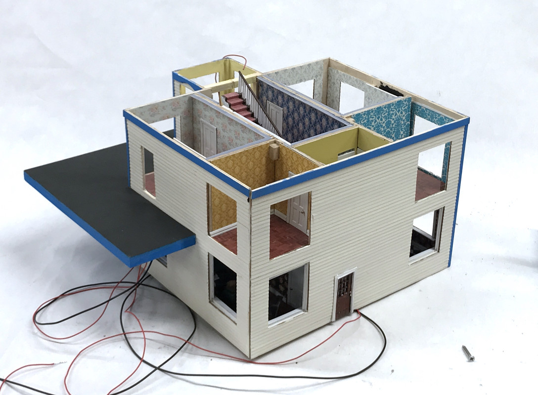
Another milestone day... The four walls are all connected, the foundation is on, and I got the porch swing installed.

The Walls:

I've learned a long time ago "when something is supposed to fit and it doesn't, don't force it!" I had been putting the wall sets next to their respective floor edges for quite a while, but that's not the same as actually gluing it up so the corners meet properly. I had tried to fit it on Wednesday and saw that it was trickier than I thought so I left it alone until today. Again, I tried to get it together, but it was being resisted in a couple of spots. I went after them one by one. Some of the culprits were baseboards and crown moldings that were interfering with the same on the new walls. Others were getting the partitions to nestle next to the fireplaces. I had to remove a little slice of the 2nd floor as it was interfering with the fireplace. After trial and error, I did get the corners to mate cleanly. I glued the floor edges and the corners and didn't worry if the partitiions were glued. They're not holding any loads. Still to go on are the corner trim strips that are already painted. 

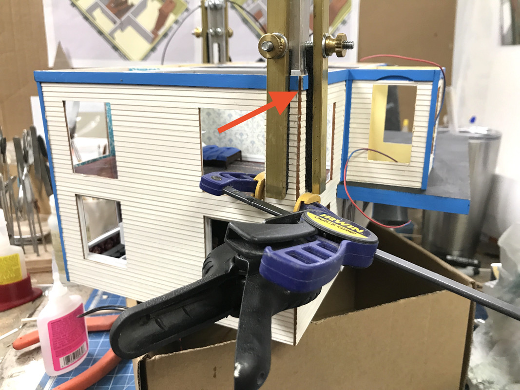
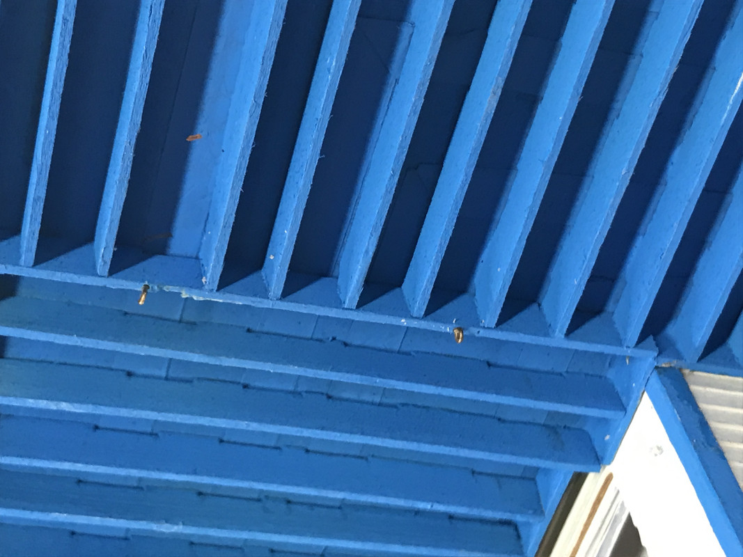
The arrow denotes a 1/32" gap resulting from incorrectly cutting the side fascia board one thickness too short. I left the other long, but that was the wrong one. One of these days I figure out how this is supposed to go.

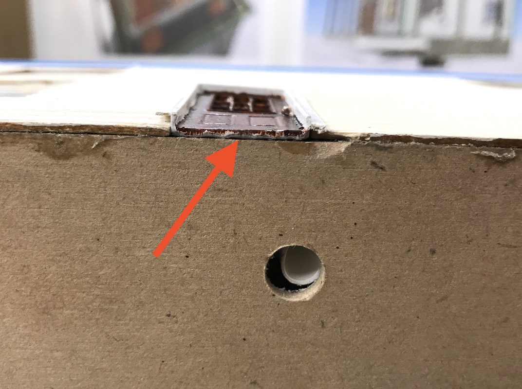
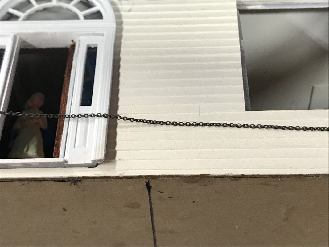
I needed to get the back door in place, but was faced with a dilemma. The door extended to the bottom of the first floor plate. This pushed the door further out of the building. I had three choices: extend the door opening higher, cut off the door bottom, or let it protrude a bit and trim it. I chose number three. You can see in this image that the door is at the bottom of the plate.

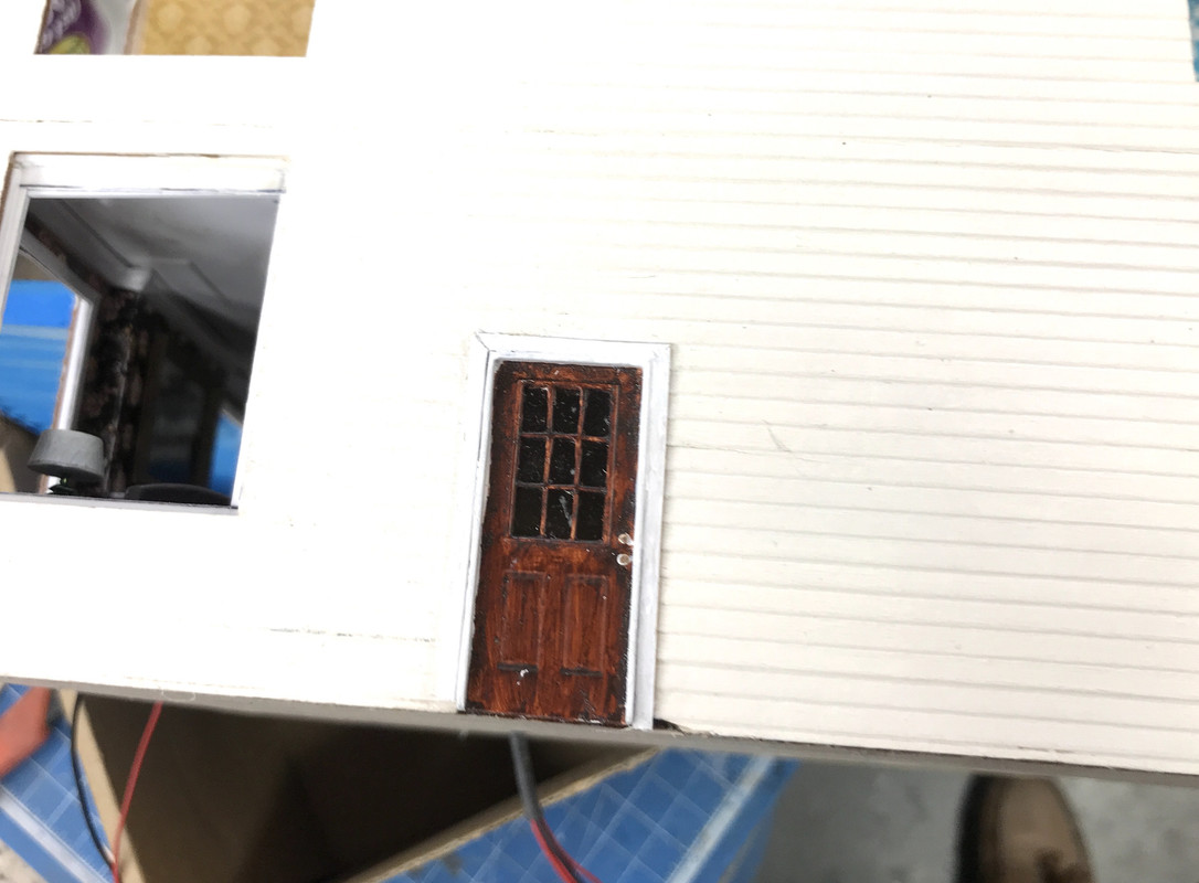
And here it is with the trim wrapped around. It may still need another coat of white. I toyed with using styrene, but ended up using stripwood.

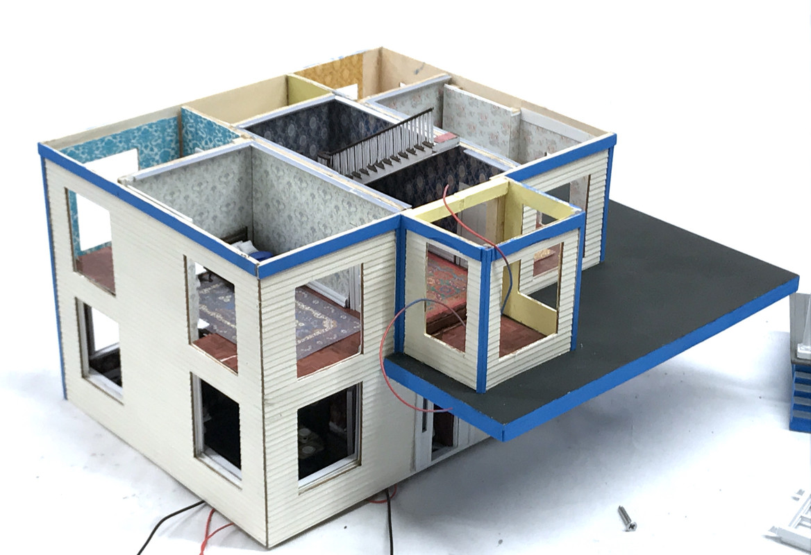
Here's the house with all the walls now connected.

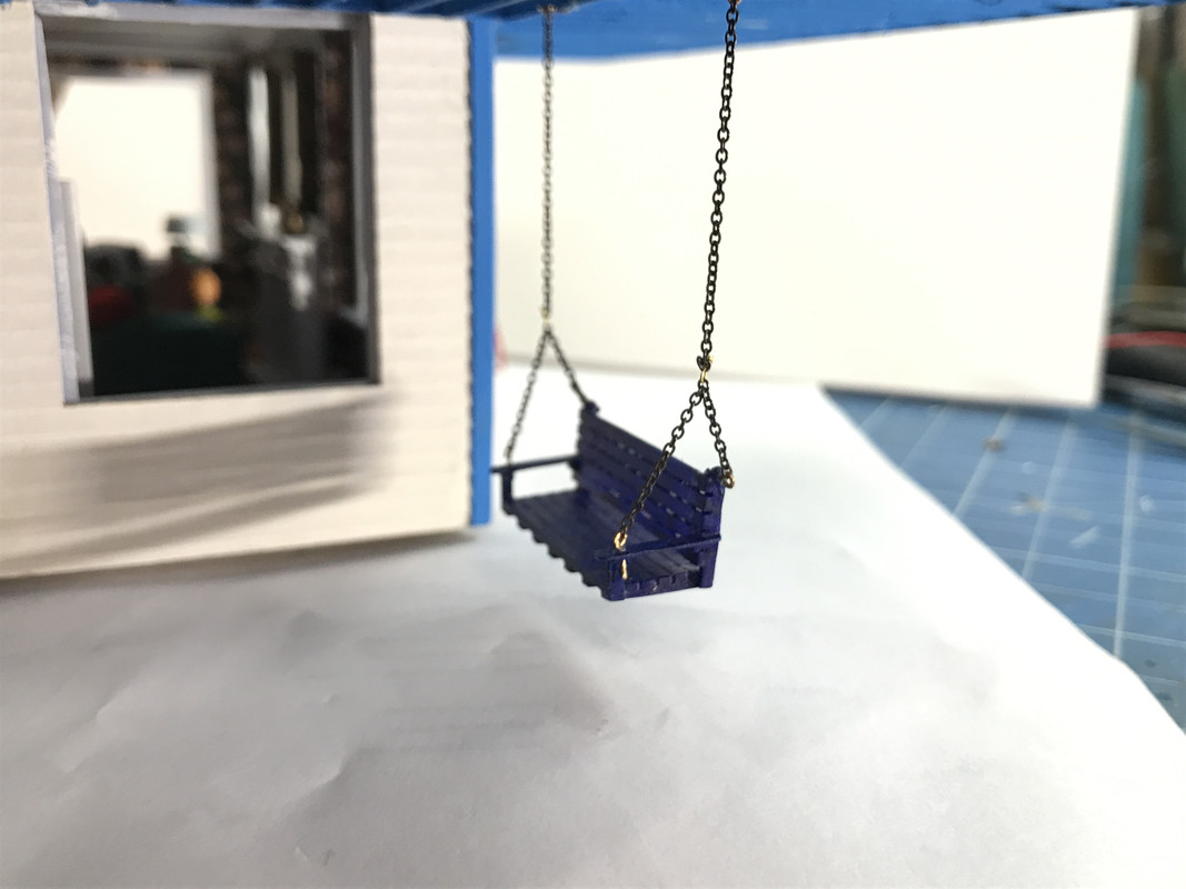
While this was drying I got working on the porch swing. It needed to be installed before the porch was installed since it would block access. I bought some 27 link chain that was bright copper colored and soaked it in the chemical blackening agent to age it.

I drilled the swing seat to receive 0.022" wire eye bolts. These are pre-bent ship parts that I bought years and years ago. I can make my own eyes too, but it's easier when they're already done. I measured the spread and drilled the balcony joists and installed eyebolts with some med CA.

I'd been thinking about the sequence on how to do this. I made short segments that would be the spreaders mounted on the seat. It was just an eyeball job based on the aglarity that looked right. I thought that the eyebolts were a little thick to directly connect to the chain links, so I used some 0.010" brass wire twisted to hold the chain to the eyebolts. I didn't like it.

Then I opened one of the eyebolts eyes and found that the eyebolt wire threaded right through the chain link. I scrapped all of the twisted wire connections and redid them all with the direct connection.

This worked great. I then cut the long chains to connect to the joists. I found that unlike the end chain links which only have one link taking up space in the loop, the middle chain link openings were too tight to let the eyebolt ring pass. I had to resort to the twisted wire method. But this this was only two connections instead of six.

This whole exercise took quite a while, but it was well worth it.

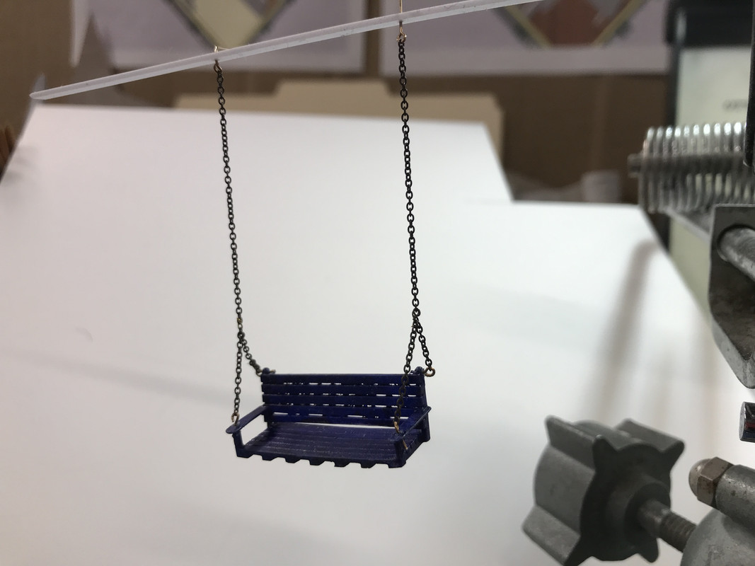
And here it is fully mounted on under the balcony. As careful as I was trying to be in getting the chains equal, I had to do some adjustment to get it to hang reasonably straight. It was also hanging too low even though I originally measured the overall height and the height I wanted the porch to sit to figure out the chain lengths, but I still had to fuss with it to get it right.

With the swing in place I installed the house proper on its foundation. I used Aleen's for this and it will dry over the weekend.

The house is now ready to receive all the windows, have the roof assembly installed and have the porch connected. My storage area is basically empty. Whew!

On another topic I want to have a dumpster behind one of my buildngs (the appliance store) and saw one of DHS Die Cast Construction Equipment site. It was $7 plus shipping, but that was a lot of money for one not-very-significant detail. Heck! I can print my own.

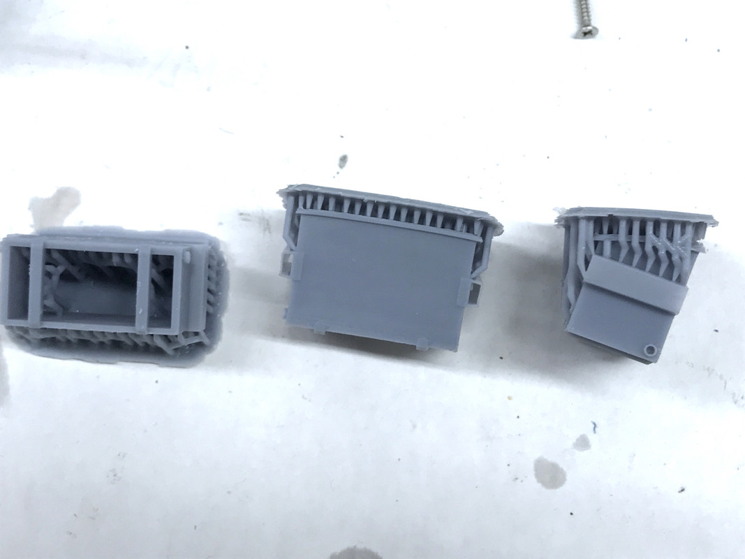
I went online, found some pictures and specs for a Waste Management 2 yard dumpster and drew it up on SketchUp in about an hour. I printed the bin and lid as two parts. The bin printed this afternoon. I did it 3-up figuring they all wouldn't be pefect. I was right, on one the supports broke free and the top rim warped. 

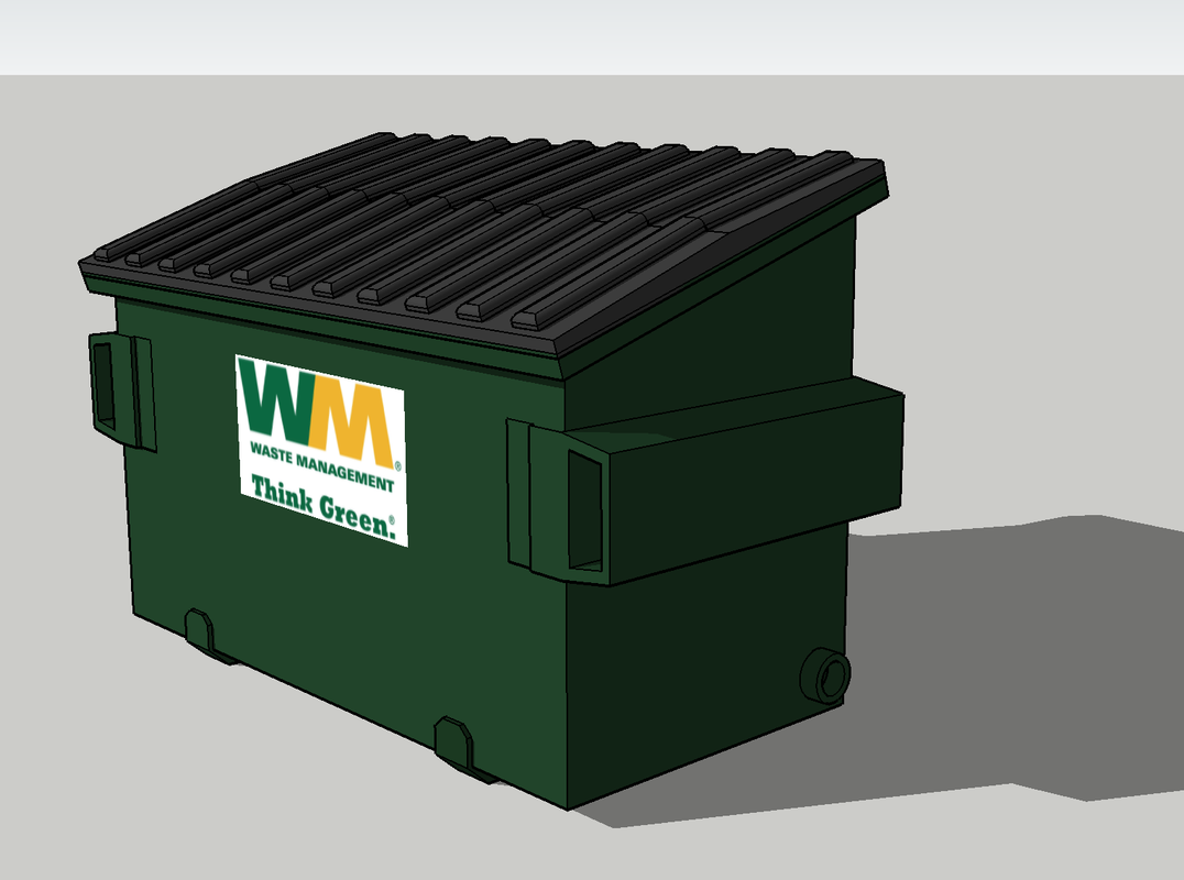
Here's the drawing that I produced.

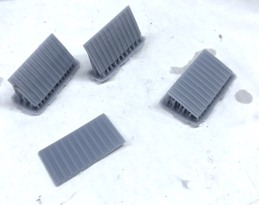
The lids just came off the Machine while I'm writing this. I set the lids up four ways on the printer to see which one was most successful. Guess what? They all printed perfectly. Go figure? I will print the decals on white-background decal paper and the inkjet.

I got the lids. You can see that regardless of their orientation, they all came out pretty good. I should get two nice dumpsters out of this run. You can see layer lines pretty clearly on the one that I printed flat on the plate. The reason? The lid had a peak... a slight taper to the middle. Even at layers of 40 microns, a slight taper causes the aliasing, just like a shallow angle line on a bitmap drawing. The more angular the placement on the platen, the greater the number of layers to cover the same distance and the less obvious each one is. It's another reason to print on an angle.

I've put this drawing up on SketchUp's 3D Warehosue. It's pay-it-forward. I've downloaded a lot of stuff on that facility and put stuff up there whenever I have a model that's worth sharing. I had to thicken the walls on the lifting lugs. They're just think plate steel, but that woud be too thin in scale to be a functional model.

This little project will be all finished on Monday and I'll show it to you. With a 3D printer, SketchUp and an inkjet printer, the capabilities are almost limitless.

  • Member since
    October 2019
  • From: New Braunfels, Texas
Posted by Tanker-Builder on Friday, December 18, 2020 1:11 PM

Thank You;

    As you know,If I have mentioned it,I am the sitting President of the Board and Chairman of our model Museum and club. I have to keep the different departments in check. We've already spent more on the " Kids Run The Train" this year just to have committed projects for the H.O.T. Money request. The autos would really stuff it up tight!

     I guess I will start hitting the Flea Markets for something close!

  • Member since
    March 2012
  • From: Louisville, KY
Posted by Builder 2010 on Thursday, December 17, 2020 6:25 PM

Due to the absolute probability of nobody seeing any of that front door detail from 5 feet away, I'm going to forego the stained glass, but thanks for the input.

Here's a good place to start looking for die cast cars. There are huge price differences in what's available from jewel-like resin models from NEO to plastic or die cast toys from various Chinese sources. There are several high-end British companies like Brooklin that produce splendid models, but they run $100+ each. I find NEO to be the most detailed 1:43 cars avaiable. 

https://www.diecastdirect.com

The other big die cast car vendor is American-Excellence. I've bought from both.

https://www.american-excellence.com

BTW: 1:43 is British O'guage. If you cut that scale in half you end up with 1:87 and that just so happens to be the global standard for HO (i.e., Half-O) scale. American O'scale is 1:48 which, as you know is also a great plastic modeling scale. Most model die cast cars in that size rang are 1:43 since many of the big collectors and builders were Bristish. They're slightly oversized for O'guage trains, but no one will notice. 

Getting true 1:48 car models is difficult. However there are some construction equipment models in true 1:48 (Classic Construction Models)

https://ccmodels.com

and many, many in 1:50 so they're slightly undersize. You see the most size troubles when you have a 1:43 car working with a 1:50 bulldozer. Oh well... CCM's models can get quite expensive especially if they're brass models.

http://www.dhsdiecast.com

This will get you lots of choices.


  • Member since
    October 2019
  • From: New Braunfels, Texas
Posted by Tanker-Builder on Thursday, December 17, 2020 11:33 AM

Hoo Boy!

 Now that's Awesome! Speaking of Stained Glass. Did you know you can use thinned model Car candy top coats to create it? Also you mentioned a Conversation. Most folks around here would say," What's That" .Oh, and one more thing. I am looking for twenty,Count them Twenty assorted Vehicles in " O " scale . Can you suggest anyone particular Mfgr? This would be for the rail Museum's Kids Run the Train layout which is Lionel " O "  and American Flyer "O27".

  • Member since
    March 2012
  • From: Louisville, KY
Posted by Builder 2010 on Wednesday, December 16, 2020 6:18 PM

Thank you! it's a really nice color which I didn't have to mix... right out of the bottle. I have a ton of images today. I had a long work session and covered a lot of varied ground requiring picture taking.

I started the session completing the porch: locating columns, gluing them in and installing all the lattice.

After deciding the setback, I marked it with the digital caliper used as a marking gauge. I then figured out the spacing using a metric ruler, calculator on my phone, and a pair of dividers (old school sort of). I then drilled a pilot hole to keep the 1/16" drill in place and drilled the seven holes with the drill in the Dremel. Because of the different lengths of the two sides, the spacing differed on each side.

I glued the columns in place with Gel CA.

Two columns were a tad short so I shimmed them with some Bristol Board.

I glued the steps in place with Gel CA and then reinforced the joint from behind with a piece of 3/32" square basswood. I then installed the lattice starting with the steps left side. When I had to joint two pieces of lattice I glued it to a small backing piece cut from the lattice's fret.

Not only did I reinforce the step joint, I also added some square stock to all the lattice corners.

I set this aside and used a cosmetic sponge to highlight the foundation stones. I used Nato Black, Flat Aluminum and White to add some interest to the field stone foundation. This is a common foundation material in Philadelphia where I grew up.

It was time to start getting serious. I glued the balcony to the front/right side of the building. It needed clamping and it helped bring that critical subassembly into square. I used Aleen's and then backfilled the joint with Med CA. The two red leads that are coming up through the turret floor feed the grain-of-wheat bulb that will light the cupola. I will have to splice these two leads to the two coming down from the roof assembly.

I set this aside and got lunch. When I got back to work I glued in the first floor to the front and right walls. Again it needed some strategic clamping to put it together and again I used a combination of Aleen's and Med CA.

I set this aside to dry and decided to attack the site situation. It took six trips under the layout and as many climbing around on top. Luckily, even at 75, due to my regular use of the bike and elliptical, I still limber/strong enough to do this. Frankly, when I started rebuilding this layout in 2012, I didn't know how many years I would be able to do it, but since I am, I'm still doing it. I can only reach this site by scooting under the platform and coming up in the gap at the back of the town between the gulchs. So each time I had to get onto the platform I first had to go underneath.

I'm moving the Gravely Building out of its position and putting it at the layout front facing away from the viewer. I had to disconnect it's power leads and, of course, the first two wires I disconnected were not the correct ones and had to get underneath again to do it right.

This is what the site looks like.

I took a piece of Strathmore Paper and measured this space and again, it took several climbs onto the layout to get it correct. I use a piece of packing dunnage which resembles a paper honeycomb to protect the track and my knees when crawling on top.

It's a tight fit! The picture distorts the fit since the black balcony floor is above the paper by 3 inches so it's not really overlapping as it appears.  There is a nice space in the back for a garage, and Rail Scale Models has a nice old style garage that would work nicely.

Here's Gravely tried out it its new location. Another reason to NOT GLUE you buildings in place.

And here's the view from the layout's edge. I'm going to add some details in the back. I have a nice Tichy fire escape kit that I'm going to use. I think I'll add a window or two in the rear with the fire escape and then have some trash/junk piles to roughen it up a bit. Adding a 3rd floor window is going to destroy that nice add mural. I have to plan the sight lines carefully so you can still look into Nighthawks. 

With the wall and floor dried I tried it with the newly completed porch. The gaps you see at the column tops will be closed when it's put up into the final position.

I went to put in the front door so I could correctly re-locate the two folks that would be posed there. I found that putting the door opening inward now made it impossible to get the door assembly in. I broke the joint, put in the door frame and then re-glued the door in place. With that done, I was able to put the folks back in position. You're not going to see hardly anything of that wonderful staircase. You can't see it through the open doors from the side rooms, and you can't see a whole lot looking in the front door. I spent a whole lot of hours on that foyer. One saving grace will be the illumination. Whatever you can see will be well lit.

I had to do more surgery on the 2nd floor plate. The changes I made to the wiring bundle caused some of it to interfere with the hall closet's ceiling. It was forcing the 2nd floor upwards. I took the Dremel and router and drastically cut away most of it. I kept checking to see if the wiring cleared. I had to sacrifice some crown molding that you'll never see. In fact, I didn't even have to have the closet hiding the wiring.

Gratifyingly, the staircase was not difficult to glue in by simply running a bead of med CA down the seams that connected it to the 2nd floor. My plan to attach the stairs to the 2nd floor and then drop it over the first floor with no first floor gluing. The reverse would have been impossible since you had to contort the stairs to get them to nestle into the 2nd floor. You'll see much more of the staircase through the turret windows in the 2nd floor since there's that big wall opening into the stairwell.

Here's looking straight down at 2nd floor as I'm attempting to get the left and back walls in place. There are some pinch points that will have to be massaged to get it into place, but that will wait until tomorrow.

Whew! Big day finished.

  • Member since
    November 2009
  • From: SW Virginia
Posted by Gamera on Wednesday, December 16, 2020 11:19 AM

Grumble, no matter how carefully you plan there always seems to be something that doesn't fit... 

Great job bringing everything in line! I really like the white with blue trim, it looks better everytime I see it. 

"I dream in fire but work in clay." -Arthur Machen


  • Member since
    March 2012
  • From: Louisville, KY
Posted by Builder 2010 on Tuesday, December 15, 2020 4:50 PM

Exercise and work day... can't get much better than that!

Got the touchup painting done on the building trim. Piece of cake. 

Did a lot of painting. I did have another "Hanukkah Miracle" since my trim blue, not only lasted for all the painting, but I actually have some left for any accidents that may occur. I painted the edge boards of the porch, the entire edge and framing of the balcony, and the front steps, including the gray stair treads. I used MicroScale Liquid Mask to mask the LEDs before the airbrushing began.

After airbrushing the steps blue, I hand-brushed the gray treads.

I also painted the porch-bottom lattice. I didn't try and get them perfect since in real life, these lattices are not generally well cared for.

I drilled the bottom of the columns 1/16" with the drill in the Dremel Flexi-shaft after drilling a small starter hole with a pin vise. Unlike styrene, UV resin doesn't melt and you can power drill it without creating a gooey mess. The pins facilitated sticking them in foam to repaint all the repairs I did on them. I airbrushed them Tamiya flat white.

I finished opening up the small door openings and got them fitted without binding. When they were binding it was causing the thin wall to warp a bit so they needed to be a slip fit.

Last thing I did was start glazing all those windows. The task started with the doors. My laser cut demi-lune window acetate needed so triming since it was a little oversized. I never did laser cut the side lights for the front door. I just cut some scrap acetate from the fret for them. I had been toying with the idea of making some stain glass, but it's really not going to show up very well. I did put stain glass on the transom lights on the distillery and you really don't know they're there.

I got eight main windows glazed and have about 10 more to do tomorrow.

And with that, the final assembly will begin. My estimate of early January was too conservative for the main building. I find with modeling, once all the subassemblies are finally complete, the main assembly goes pretty quickly. However; I have not started working on the site itself and that will take some time. I know what it looks like in my head.

  • Member since
    March 2012
  • From: Louisville, KY
Posted by Builder 2010 on Monday, December 14, 2020 6:08 PM

I like that you like it.

The fascia boards are on and I closed up the gaps around the chimneys where I had to enlarge the slots to get the roof on. I used basswood pieces shaped to conform to the roof edge profile. I filled any remaining gaps with Bondic. 

I painted all the Fascia.

I then went back and flashed the chimneys with my last pieces of treated copper. Didn't want to mess around with treating any more so I'm glad I had enough.

So NOW the upper works are 100% complete!

I was able to carefully disassemble the front door and reverse it so it's now opening correctly inward. Luckily, I detailed both sides of the door so it didn't take much work getting it ready. Interestingly, when I separated the door, the Bondic that was in the middle of the joint was NOT cured since the UV light didn't reach it. And of course the two folks standing in the foyer were now right where the opening door was. So I had to rip them off and will re-glue them when the walls are in place so they'll be in the right spot. The standing man in the living room also had to be detached since he was where the fireplace hearth base was going. The room is NARROW.

I painted the smaller doors with mahogany like the main door. I then test fit them in their openings and realized I hadn't paid too much attention to these since they didn't fit the holes. They're almost 1/8" too long and slightly too wide. Easy fix... make the openings fit the door. They needed to be lower on the wall anyway. 

I painted all the other trim and corner posts on the walls in anticipation of them being joined. There's just a couple of spots where the blue leaked under the masking. I'll touch this up tomorrow.

Next up is glazing all the remaining windows and installing them. I don't have much of the trim blue left and I'm hoping that it will hold out for the porch and porch steps painting. If it does, I'll classify it as another "Hanukkah Miracle." I'm going to install 1/16" brass pins in the porch columns to hold them for painting and then to provide a solid attachment points for installation. 

  • Member since
    October 2019
  • From: New Braunfels, Texas
Posted by Tanker-Builder on Saturday, December 12, 2020 9:31 AM

Oh Boy! I am liking where this is going.

  • Member since
    March 2012
  • From: Louisville, KY
Posted by Builder 2010 on Friday, December 11, 2020 6:20 PM

The fine pen is a good idea. I'll get one of those.

And okay... no TV. These people are strictly old school, they sit in the living room and have conversations.

It took approx. 3 hours to fully paint the folks in two sessions. It's a highly diverse group that reflects the street where we live.

The standing younger guy and his "mom" will be greeting people at the front door.

In the dining room we have the older dude and his grandson?. Put a hat on her and she looks like Queen Elizabeth...

And there's a small gang in the living room.

I painted the front door mahogany and attempted to give it some grain using two coats.

All the folks are glued in place so the interior is ready to place when the exterior is done. To that end I put two coats of craft paint "vanilla" on the walls and then masked all the trim. I then gave the trim and tape edge a coat of Dullcoat to seal the edges and pre-fill the grain for the trim blue that I'll paint on Monday.

While that was drying I decided to add more trim to the roof/Mansard junction. The roof was not fitting tightly and I didn't like it. I'm installing fascia boards that will be painted trim blue. I got about 1/3 applied before running out of time. 

I just wasn't happy with that top edge and the new trim helps.

Everyone have a safe, socially distant weekend!

  • Member since
    October 2019
  • From: New Braunfels, Texas
Posted by Tanker-Builder on Friday, December 11, 2020 8:50 AM

Please, Please, Don't put a telebishion in dere.

     When we got ours( a Monster that also contained a Radio, Record player and Record storage) the family started watching, and the Piano and Instruments we all played got ignored. Then no one sat and talked. They just watched that ridiculous tiny screen.

      Plus the worst of all, We stopped doing reading night. That was when the grandparents and parents would sit and listen to us kids read from our Schoolbooks or the Bible. Or a book we had gotten ( Gasp!!) from the LIBRARY! These were the things that went on in our old great big Farmhouse.

  • Member since
    November 2009
  • From: SW Virginia
Posted by Gamera on Friday, December 11, 2020 8:46 AM

Oh those figures are neat- the perfect finishing touch!!! 

I use a small pen with a pinpoint tip and just dot the eyes with that.

https://www.fabercastell.com/products/pitt-artist-pen-superfine-199-black-box-of-10-567199?_pos=1&_sid=59ecbfa6f&_ss=r

"I dream in fire but work in clay." -Arthur Machen


  • Member since
    March 2012
  • From: Louisville, KY
Posted by Builder 2010 on Thursday, December 10, 2020 6:11 PM

Thank you!

I almost forgot to get the House dwellers ready to move in before buttoning up the building. One of my readers of this same thread that I post on O'Guage Railroading Magazine's forum, asked if I was going to include some people. I definitely am. Most of my other buildings with full interiors are populated. One of my readers several models ago sent me some posable 1:48 figures which I was able to kit bash and use in the Nighthawks Cafe.

I had enough left over that I could get folks into the living, dining and foyer. 

These figures are true 1:48. Many O'scale figures are bigger, more on the order of 1:43 which is UK O'scale. I have some of those and they wouldn't have fit on those dining chairs or got their legs under the table.

I have a conversation group for the living room.

For the foyer I have this guy and a person that looks like his mom that I didn't stand up.

I started painting them all and decided to make it a diverse group.

I'll finish painting them all tomorrow. They'll be placed and then the interiors will be ready to install into the House. When I do this kind of painting, I stick a bit of Press-n'seal onto my work surface and use it as a disposable pallete. With figure painting you're constantly mixing in between colors. I have trouble painting eyes on figures this small. They're not very well resolved so it's hard to get the paint where it's supposed to go. Tomorrow all the base coats will be nice and dry which will help. I force dry acrylics with a TopFlite Heat Gun. I have to be careful because it puts out enough heat to melt styrene.

  • Member since
    November 2009
  • From: SW Virginia
Posted by Gamera on Thursday, December 10, 2020 11:24 AM

Oh sorry, musta missed your alternating between military and railroad kits. Looking forward to the Brad. The Meng kits I've built I've loved, though I've never built one with a full interior though. And that distillery is pretty friggin' awesome!!

"I dream in fire but work in clay." -Arthur Machen


  • Member since
    March 2012
  • From: Louisville, KY
Posted by Builder 2010 on Thursday, December 10, 2020 10:08 AM

Next up is the Meng Bradley AFV with full interior.

As I've noted, I like to alternate between challenging plastic kits and stuff for the railroad. I generally don't build armor, but the Sherman project was so much fun that I want to do another fully-detailed tank.

After the Bradley, I'm going to build another unusual railroad project, a Bourbon Warehouse (Rickhouse) under construction. I already have a superb distillery building and it needs a place to put all that bourbon, but constructed rickhouses are boring structures. BTW: There's a 3-part article on building the distillery starting in the Oct 2018 Railroad Model Craftsman magazine.

Rickhouses are just a metal-sided box with a bunch of little windows in them. Like I said, "boring"!

However, when you peel back the skin, you get this... A forest of lumber.

I drew this up on SketchUp and will build it entirely out of stripwood. Heaven Hill Distilleries has over 50 of these buildings and has probably close to 2 million barrels aging. Each full barrel weighs over 500 pounds and the new Heaven Hill Cox's Creek Rickhouse complex has buildings that hold over 62,000 of them. Just for the record, each empty barrel costs $175. That's $350 milllion in inventory just for the oak barrels and not counting the vast amounts of alcohol.

Here's the distillery I built for my railroad. I built another for the Heaven Hill Bourbon Experience Center in Bardstown, KY. The distillery was based on a single picture on the lobby wall of the current Heaven Hill modern distillery in southwest Louisville. The building depicts the I.W. Bernheim distillery as it appeared in 1870. It was razed during Prohibition. The Shapira family bought the rights to Bernheim in the mid-1930s and own Heaven Hill to this day. It was mostly laser-cut. I made resin molds and cast the chimney, vents and stacks since I was contemplating making it into a kit. In the end, it was too complex to make a kit that I could feel confident that others could successfully build.

The material handling system on the right side is a selectively compressed version of that which exists today. The building on the left is the boiler house. The picture wasn't clear as too what was on that left side so I winged it. There are detailed boilers and all associated apparatus in that building.

This was an illustration that I produced for the not-to-be-produced Bernheim Distillery Kit. The beauty of using SketchUp to design the project was the ease of creating exploded drawings for instructions. I chose not to include an interior since the window area was pretty small. The interior is illuminated. To hide the exposed tab slots I had to create addtional cover strips.

To create the elaborate crenalated adornment I had to make layered laser cut and etched pieces that laminated to give the relief. This is the laminate for the auxiliary building which I labeled, "The Kitchen".  The instructions would have been great, too bad the kit was a bear. My engineering left something to be desired.

Here's where the rickhouse is going on the layout. It's a tight fit, but it will work. The Hopper House is going to replace that blue building that across the street. I have a big Grove mobile crane that will adorn the site along with piles of lumber and dirt. Should be interesting.

And after that?? I'm thinking about building the Ryefield Models Abrams with full interior. So I have plenty of projects lined up into 2021. I like to plan ahead...

  • Member since
    November 2009
  • From: SW Virginia
Posted by Gamera on Thursday, December 10, 2020 8:40 AM

Oh cool! And I know what you mean about stuff that should fit not fitting after everything is in place- been there, done that, got the t-shirt... 

Still it's great watching you work your way to the finish line. So are you building another cool house next or a railroad related building or business? 

"I dream in fire but work in clay." -Arthur Machen


  • Member since
    March 2012
  • From: Louisville, KY
Posted by Builder 2010 on Wednesday, December 9, 2020 5:44 PM

I had a nice shipment from MicroMark (early Hanukkah Harry delivery) today taking advantage of their holiday free shipping offer. You had to order over $100.00 so I did. One of things I bought was a small powered cutoff saw made for model-sized stock. It didn't have a depth stop so I spent part of today's session building a base and a positionable depth stop. I then got back to the House.

I was able to raise the roof, and hold it with a wood block, and got inside to cut some relief cuts to clear those re-positioned wires. If I would have originally run them down the back the partitions wouldn't have some into play. But I didn't and had to do some crazy rework. I tend to not think in 3D and didn't think about just what those repositioned wires would now be interfering with. The wiring had a lot of my attention and I kept waking up in the morning thinking about how all those various leads were getting to the basement. The attic ceiling's were particularly vexing and now I know why. I had them routed poorly.

Another one of the things I bought was some #11-sized saw blades which was perfect timing since I was immediately put one to use in cutting away the attic partition through the 3/4" opening I was able to make in the roof. I took this picture through that gap.

With the relief cuts the roof just about fit. I used servo tape strips to attach the roof to the Mansard walls. The fit wasn't so hot, but it's holding. Servo tape holds like crazy.

So with that, the roof is actually done.

I started installing furnishing and the interior doors in preparation for attaching the main walls. I'm using drops of Gel CA to hold everything down. It works pretty well for this app. I started with the doors (held with Canopy Glue) and then the dining room and finished with the living room. And of course I forgot to lay the living room carpeting before installing the furnishings. And that Gel CA doesn't let go, so there was no removing the furniture to lay the carpet. I compromised and used the carpet at the doorway.

And the living room.. The doors really help with the illusion.

I put the grandfather clock in the foyer and also got some bedroom furniture (and carpeting) in place which I didn't photograph. Tomorrow I'll start working on the exterior painting and prepping all the windows for installation. I still have to paint the repaired porch columns, finish the balcony, paint and install the porch lattice screens and build the chain suspension of the porch swing. But, we're getting near the end.

Oh... and the site needs to be created! So we're not that close to the end...


  • Member since
    March 2012
  • From: Louisville, KY
Posted by Builder 2010 on Tuesday, December 8, 2020 10:15 PM

Mansard roof is about 99% complete. I just have to do some internal relieving to clear some of the newly re-routed wiring. Got the shingling done, put on the drip edge, painted the blue trim and re-painted the NATO black and installed the upper roof and Turret.

After finishing up the shingles on that one window, I went around and reinforced the upper trim edges with some UV-cured Bondic and then trimmed any excess. I put the ridge shingles on all the corners after carefully applied some PSA to reinforce this particular shingling job. They're under some tension and the self-stick adhesive has been letting go.

I then appied the 1/16" square stripwood drip edge around the perimeter of the Mansard roof. I first checked to see if I could get the turret into position with the edging in place. I was, so I glued in the edging in that front space.

When the glue dried enough so the strips didn't fall off, I brush painted the edging and underneath the eaves. I could be sloppy since I was going to go back with the NATO black and back-paint to the edging.

When I put on the black it quickly started dissolving the blue which wasn't totally cured at all. To keep my progress going I overcoated the blue in the gutter area with Dullcoat. This image was while the Dullcoat was drying. This sealed the blue and enabled me to do the black in the same work session. As I've said many times before, "I am NOT patient, I am persistent!" When I screw up it because rushing either paint or glue before it's dried.

In addition to painting the gutters, I went into the window areas and did some final touchup there too.

After painting the black touchup, the roof was pretty much done.

I needed to get the attic stair rail installed before putting on the top roof. This was not difficult and after a little trimming, I got it glued in place.

Then things got a little bit sideways. I went to install the cupola and found that the rear-most corbels impinged on the Mansard roof and it was preventing the turret from seating properly. The back corbels would have been imbedded in the roof and wouldn't have been seen, so I broke them off.

The second thing that happened was I was no longer able to get the top roof on. It was blocked in two ways. First the chimneys prevented sliding the upper roof forward so it slipped under the turret roof. I had to remove the turret which I had just glued in place. Luckily, I used Aleen's PVA instead of CA. It wasn't yet cured so the turret came off easily.

And then problem number two reared its head. I couldn't drop the roof over the chimneys. I could get one notch in on one side, but then it looked like this. 

First I thought all I needed to do was make the relief slots deeper and I did this. 

But then I found that at least on side had to be wider to drop over the chimney's width. So more surgery and I did this.

I had to re-attach the LED leads whose copper foil had failed, and realized that these leads needed to join the leads from the 2nd floor ceiling that were going down through the back-center (un-windowed) room. I was going to bring them down through the turret joining the non-polarized leads from the grain of wheat bulb in the cupola. That really wasn't the best route. I re-routed the attic leads backwards across the attic ceilig and camoflaged the leads with white duct tape, and then drilled a hole in the rear of the attic floor to pass the leads through. I had to made more clearance in that front beam where the wires go over it. And I will also have to cut some relief in one of the attic partitions since the wires back there are holding the roof from setting down correctly. But other than that, the entire upper works are finished! This was the most complex part of the project and I'm happy that it's now in the rearview mirror.

The touchup painting really tightened up the total deal. After gluing down the upper roof I'll have to flash around the chimney notches and maybe build a TV antenna... although I haven't printed a TV for the interior. I can... I printed two versions of 1950s TVs for the Appliance Shop.

I tested the lighting and took a picture through one of the windows. It looks pretty.... atticky... if there's such a word.

I'll finish up all these odds and ends tomorrow and then get cracking on finishing up the main building. If I need to produce a TV I better do it soon since the furniture's going in and then it's going to be closed up. I have to paint the exterior walls and do all that detail painting for the stone foundation. I'm going to join all the various parallel circuits in the stone base so only one set of leads goes below the table level.

  • Member since
    March 2012
  • From: Louisville, KY
Posted by Builder 2010 on Monday, December 7, 2020 8:34 PM

Happy Monday!

Finished the back Mansard wall, the left wall with the other chimney and made a good start on the final little bit.

The top trim strip needed some gluing help in the upper right corner so I used med CA and of course it soaked through and made a bit of a mess. I will match the gray and paint it. I'll also add some minor weathering which will help blend the paint in. The shingles really trim up that ragged bottom edge. Hides a lot of ugly.

On the second chimney wall I tried changing the flashing method on the chimeny. I marked the wall's curve on the chimney's brick side and then applied the flashing with the chimney off the model. Again, I had to cut little fingers on the side of the flashing that needed to stretch around the curve. I had to apply the gel CA and install the chimney with the flashing attached in one go. I did this and then saw that I had cut the fingers on the right side flashing facing in the wrong direction. That wouldn't work! But it was too late to pull the chimney off and redo, so I just ripped off the bad flashing and did the right side the way I did on the other chimney, i.e., piece by piece. 

I also realized I didn't have to put an entire strip of shingles behind the opened-back portion of the chimney since it was out of sight. Instead, I just put pieces on both sides just long enough to nestle behind the gap.

I got flashing on the last window and then started to put on its shingles when I ran out of time. I will finish up the Mansard roof tomorrow. I had to install the attic stair surround railing before I forget. I also have to attach one of the LED leads whose foil tore in all the handling.

See y'all tomorrow.

  • Member since
    March 2012
  • From: Louisville, KY
Posted by Builder 2010 on Sunday, December 6, 2020 10:40 PM

This was the little bit of work I got done on Friday. Had to make a Hobby Shop run (Soically distanced with Masks) since my med CA was kicking and getting too gooey. 

I had to make that second batch of flashing. This batch even came out more grungy than the first. I like it. This should be enough to finish the job.

I then almost got the long roof shingled. I'm well more than 1/2 way through the shingles and should be done tomorrow or Tuesday.

It's amazing how the shingles make the whole thing come together.

Tomorrow's Monday so back to the shop.

  • Member since
    March 2012
  • From: Louisville, KY
Posted by Builder 2010 on Saturday, December 5, 2020 11:16 AM

Thank you all! Let me answer the questions in their order.

The shingles are a product of Rail Scale Models. They offer an entire line of shingles in different styles (among lots of other model railroading related products). I'm using the Victorian mix which includes an equal mix of fish scale and square plus the Starter Row and Ridge Shingles set. Here's a link:

https://www.rail-scale-models.com

Re: 3D printing. I've gone further. I've sent a proposal to Aaron Skinner (FSM's new Editor-in-Chief) about having me author a Kalmbach Book on "3D Printing for the Model Maker". Most of what I've read about this topic deals with creating trinkets or fantasy figueres or gets into industrial Additive Manufacturing which is way beyond our needs.

While helpful, it doesn't address the first steps, i.e., creating the drawings in the first place, or creating parts that have to interact with others and all in small scales. I don't know how many pages it will be, but it could get into the weeds pretty quickly. I have not outlined the content until interest is shown on their end to the concept.

Aaron has chosen (so far) to not respond in any way. Some pressure from my faithful followers could prompt a response. It the answer is "No", then so be it, at least let me know you received the communciation. I've been published in FSM in 2001 with a soldering article and authored a few Tips and Tricks over the years. The topic is too complex to be a single article. It could be a series, but FSM doesn't roll like that.

  • Member since
    January 2010
Posted by rob44 on Saturday, December 5, 2020 9:14 AM

A truly wonderful explination of resin 3D printing and a fantastic build. May I suggest you contact FSM to see if they can more this to a more public space or consider publishing it?


You may want to also explore putting it on some seperate web site.


Rob

  • Member since
    October 2019
  • From: New Braunfels, Texas
Posted by Tanker-Builder on Saturday, December 5, 2020 8:38 AM

Hey!

        Did you cut all those fish scale shingles? Or did you buy them?

JOIN OUR COMMUNITY!

Our community is FREE to join. To participate you must either login or register for an account.

SEARCH FORUMS
FREE NEWSLETTER
By signing up you may also receive reader surveys and occasional special offers. We do not sell, rent or trade our email lists. View our Privacy Policy.