SEARCH FINESCALE.COM

Enter keywords or a search phrase below:

Monogram/Revell "Yankee Lady" Enhanced Build

7419 views
94 replies
1 rating 2 rating 3 rating 4 rating 5 rating
  • Member since
    March 2012
  • From: Louisville, KY
Monogram/Revell "Yankee Lady" Enhanced Build
Posted by Builder 2010 on Wednesday, August 10, 2016 9:16 PM

In the 70s, when living in a townhouse in Bucks County, PA, I would build models in the garage in the Summer and the young boys living in our cul-de-sac would sit and watch me build. One such kid, now 50, continued building models and being a fan of military subjects. For his 50th birthday he got a ride in one of the few B-17s restored and flying; the "Yankee Lady". Yankee Lady represents a late model B-17G in natural metal and having the "Cheyenne" tail gunner's glazing. After his flight he went out and bought the Revell kit, but as a father and accounting professional he realized he wouldn't be building it for years, and thought of asking me to build one for him. He offered a commission, but my wife forbid me from taking any money from him. Since I live in Louisville and he outside of Philly, I suggested he take his kit back and I'd buy it here. I also was able to get a great set of decals for the "Yankee Lady". 

In addition to the decals, I decided to make the kit more accurate by buying the Verlinden upgrade set and a set of new engines from Eduard. The Verlinden set has new turbos, struts, guns, and a PE Cheyenne tail gunner's position. It also has a lot of little bits to detail the interior. I just read Toshi's build of this model and he used the entire Eduard set which has a terrific set of flight deck instruments. I know from experience that very little of this stuff can be seen unless you're building the see-through verison. I am not so I'm really going to watch how much time I'm going to spend on things that will be invisible.

The last totally enhanced build I did was a Tamiya Missouri with Eduard PE, laser cut decks, steel prop shafts, brass props, etc. etc. This came out so well that I was offfered a display space in the Captain's Cabin of the real Missouri in Pearl Harbor, if (and this is a huge "if") I could get it there. I couldn't find a way to do it, so it sits in its case upstairs. That model really built my confidence in handling high-detail modeling using PE.

I started building with the turbos. It meant some surgery to cut out the kit's molded parts and CA the resin parts. Before getting into the nitty gritty of this build, here was another B-17 I built. This one was built on commission for a fellow who flies model jets. He hates building all wood kits and asked if I could build it. It has four OS F-26 four stroke engines. 

It was an old Royal/Marutuka kit. We wanted to modernize it so I included separate servos for each elevator, aileron, and one for each engine throttle. Changing to four strokes necessitated putting the fuels tanks in the wings (prototypical fashion) which complicated things more. The young man in the background is my older grandson (now 15) and the plane flew nicely in April 2011. I studied a lot about B-17s in building it, and chose a specific tail number. It was a plane that never left the USA, used for training and had very few guns and artwork. It was an ideal candidate since I could not get decals and had to make my own. Being an all-balsa kit, it was very difficult to create.

This model will be much different.


  • Member since
    March 2012
  • From: Louisville, KY
Posted by Builder 2010 on Wednesday, August 10, 2016 9:37 PM

To open up the turbo space I used a carbide router with my Dremel and Flexi-shaft. I had to use a very slow speed since if I went faster the styrene would melt and clog the cutter. At the slowest speed the bit wanted to chatter and dig in, so it took a lot of concentration to keep it on track, but it worked. I also sized a drill and opened up the waste gate a bit so it looked more like an open pipe.

The turbos have a fatter side. It faces towards the middle so you have to be careful before using CA. The turbos consist of separate PE rotor, resin convection cooling duct and PE cooling duct clamp and resin exhaust pipe.

I found some good pictures of the Yankee Lady and it's engine and turbo details to get a good idea of the color of these things.

There's a lot of colors there and it should be fun to get it to look right.

  • Member since
    March 2012
  • From: Louisville, KY
Posted by Builder 2010 on Wednesday, August 10, 2016 9:43 PM

I changed out the kit tailwheel with the Verlinden resin replacement. It's not straight forward since only the lower part of the strut is replaced. You must cut off the lower part with its attached 1/2 wheel and replace it with the resin struct and new tailwheel. Since this piece was going to carry some load, I don't trust just a butt-jointed CA joint so I drilled an 0.021" hole centered in each piece and use 021 brass wire to reinforce the joint. This really strenghtens the assembly.

I'll wait to paint this.

  • Member since
    March 2012
  • From: Louisville, KY
Posted by Builder 2010 on Wednesday, August 10, 2016 10:14 PM

Up next was the radials. The moldings were so fantastic that I had to get into them. The sprue portion on the engine proper is huge and starts at the exhaust ring at the engine's rear. At first I started to attempt to cut it off with the razor saw, but got cold feet. There had to be a better way. I have a Taig model maker's lathe. While not robust enough to machine anything substantial, for real miniature work it is a gem. I've had it for over 30 years and it's been great. They're still being made right here in the good old USA. At first I tried to chuck it up by holding the scrap but it put the parting tool very close to the rotating chuck draws. The part has a nice 0.293" hole in the middle to attach it to the existing model. I used this hole to my advantage.

I machined an aluminum mandrel with a tight fit in the hole so I could use a very narrow parting tool as very slow speed to part the scrap off the back of the motor. It worked!

Look at the details cast into the back of that motor. Those details will be completely hidden when the cowl and cowl flaps go on.

I simply couldn't have sawn that part off with this accuracy. I was really worried about maintianing the squareness of the cut and not cutting into details or not leaving so much that I would have to sand an 1/8th inch of resin off.

I used the same idea to cut the scrap off the gear cases. Only this time I had to chuck it up by the scrap end and use the parting tool only a 1/16" away from the spinning chuck. I took it very slow and the cuts worked. Again it was much better than using the razor saw. I have since tried this technique to separate the scrap from the cowl flap part and it worked there too.


  • Member since
    March 2012
  • From: Louisville, KY
Posted by Builder 2010 on Wednesday, August 10, 2016 11:00 PM

After a light sanding on the gear cases, I CA'd them into the engine block. At this point I need to paint the engines. If you wait until later, everything is blocked by the ignition wiring. After studying some pictures of the R-1800 in B-17s, I chose to paint the cylinder barrels burnt iron, heads flat aluminun, between cylinder baffles flat black and gear case intermediate blue. I think that mix is a little darker than it should be and I may adjust it lighter.

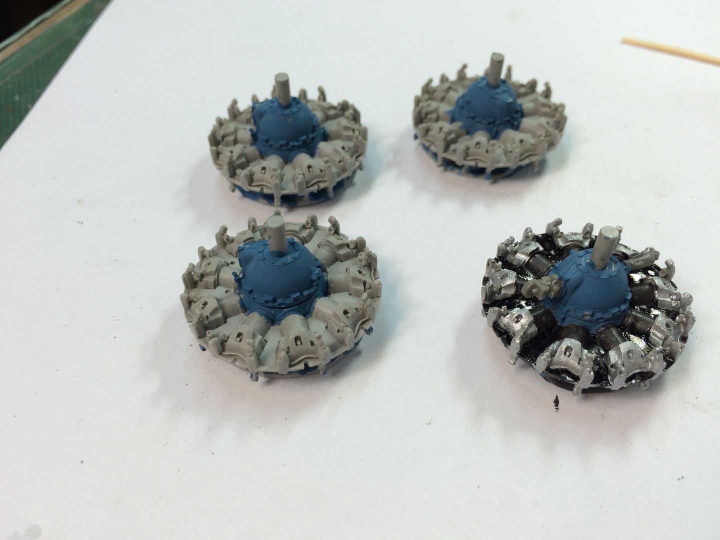
On the right front engine, I glued the magneto and some other component onto the gear case. These are painted the same blue. I made two mistakes here. First, the magneto has a belt drive pulley on it. It's not supposed to face directly back, rather it's supposed to face between those two cylinders. I popped it off and reglued it. Second, neither of these parts should be put on before the pushrod tubes are in place since they partially block where those tubes go and make a tough installation even tougher.

I decided to completely finish one engine to see how to do it before building the other three. Just like the RC model, four-engine aircraft require you to do a lot of things four times. It was really onorous when I had to hand shape 24 balsa blocks for the four nacelles. Ugh!

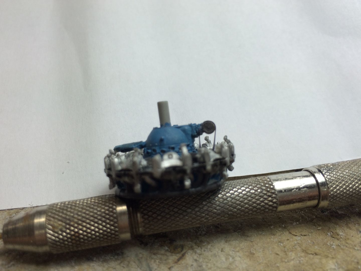
The magneto has a tiny piece of PE that simulates that belt. It just wasn't cooperating. It was taking close to a half hour to get this one piece on and it just didn't get done. So I needed to find another way. I have the wide and narrow E-Z Line for ship rigging and other cool stuff. One of the nice things about E-Z Line is its instant affinity for CA. I was able to affix it to the baffle, run it around the pulley and then glue it back to the baffle. I added a little tension so it looked like a belt.

I realized that I better start getting those pushrod tubes. They're cast in a block of 18. They're very small... ridiculously small. I'm 71 and need a lot of magnifcation to do this stuff. They also had a propensity to disappear into the quantum rift. For those that don't know about the "Rift". It's the place that small parts go when they pop out of tweezers or leave the work surface for whatever reason. I firmly believe that objects of certain mass or below can actually zip out of our universe and go somewhere else. They may or may not decide to reappear in our space. I've had parts drop right in front of my eyes straight down to the workbench and then... simpy not be there, or anywhere. Then the next day, there's the part sitting right in fron to me. Don't believe there's a rift? Then you explain it. 

Well, I lost four of these pushrod tubes and broke a fifth, forcing me to make my own out of .032" brass rod. The model's measured out to .027". I have 0.021 and 0.032 brass so the thicker had to work. I would like to know how Eduard creates these parts in the first place. I suspect they're working in a much larger scale and then using CNC mills to reduce it when making molds. There are details are the rods base that I found difficult to reproduce.

The resin parts should snap into a tiny pocket on the gear case and another under the rocker arm. I found that in most cases I had to remove a tiny amount of stock so they would just snap in without bending too much (that's how I broke one). I had to measure and cut the brass replacements, and then keep adjusting their length and round their ends so they too would just snap into position. A drop of CA at each end secured them.

So here's where I am after today's work. I put the kit's plastic part next to this motor for comparison. So much of this cool stuff will not be seen, but I'll know it's there. There are still more pushrod tubes and all the ignition harnesses.

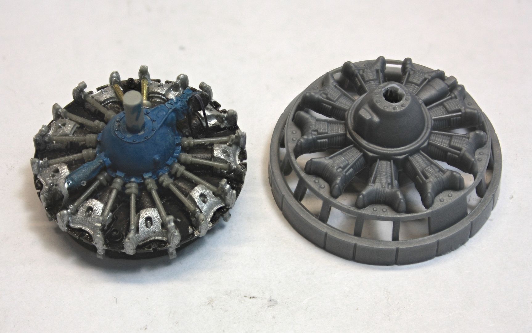
Pushrod tubes will be painted black with aluminum trim at the bottom. Once painted, my brass replacements won't be so noticeable. For the next engine, I'm going to cut all the pushrods off their block first and put them in a container. Some of the parts loss came when my tool bumped the block and a bunch separated and took off.

While building this model I'm also working on my extensive model railroad. Working on little details is a nice break from building an 8 foot mountain out of cardboard and plaster.


  • Member since
    March 2012
  • From: Louisville, KY
Posted by Builder 2010 on Wednesday, August 10, 2016 11:06 PM

Here're a few shots of the R-1800s in the B-17.

I'm definitely going to repaint those engine cases to something more like this gray color.

  • Member since
    March 2015
  • From: Streetsboro, Ohio
Posted by Toshi on Wednesday, August 10, 2016 11:33 PM

No way!!!  WOW!  What you're doing is absolutely amazing.  You actually milled the resin piece.  Again, WOW!  I am definately following your build with great interest.

Toshi

On The Bench: Revell 1/48 B-25 Mitchell


Married to the most caring, loving, understanding, and beautiful wife in the world.  Mrs. Toshi


  • Member since
    August 2013
Posted by Jay Jay on Thursday, August 11, 2016 8:45 AM

WOW ,thank you so much for this excellent W.I.P.

I'm folowing with great interest because I have this same kit in the stash and i'm wanting to super detail it, so your post is teaching me how and I'm very grateful.


 I'm finally retired. Now time I got, money I don't.

  • Member since
    June 2014
Posted by BrandonK on Thursday, August 11, 2016 9:42 AM

Fantastic work. I have many of the same parts for one of my kits in the stash. Your work will be of great help when I dive into mine.

BK

On the bench:

A lot !! And I mean A LOT!!

2024 Kits on deck / in process / completed   

                         14 / 5 / 2  

                              Tongue Tied

  • Member since
    November 2009
  • From: SW Virginia
Posted by Gamera on Thursday, August 11, 2016 10:23 AM

Yeah, very impressive work!!! 

And I know all about that 'Rift'. Sometimes I wish I'd fall though and find all my missing parts but then I'm not sure I could get back again... Alien

"I dream in fire but work in clay." -Arthur Machen


  • Member since
    May 2013
  • From: Indiana, USA
Posted by Greg on Thursday, August 11, 2016 11:14 AM

This is a great WIP so far and I do hope you keep it going.

Just had a blast reading all of your tips and details about how you've done stuff so far. The WIP vs kit part comparison of the front end of the redials is awesome.

And now I want to go buy a small hobby lathe which I need like a hole in the head, so darn you for that. Stick out tongue

  • Member since
    January 2015
  • From: Tumwater, WA.
Posted by M. Brindos on Thursday, August 11, 2016 11:35 AM

lol, Greg. I've been wanting one for 20+ years lol.


Now, this is enhanced alright. Impressive start to be sure! I'm following.

- Mike Brindos "Lost Boy"

  • Member since
    December 2002
Posted by 7474 on Friday, August 12, 2016 9:54 AM
Nice job on the kit so far, I'll be following this. My grandpa was a model railroader and also used a benchtop lathe to make the wheels more scale, I inherited his after he passed away, I used it once but that experience scared me away... keep up the great work.
  • Member since
    February 2003
  • From: Central Ohio
Posted by Ashley on Friday, August 12, 2016 10:44 AM

Fantastic job so far! Being in the sixth decade and still trying to model, I sympathize with your vision issues. Plus, I drink too much coffee and can toss a small part into oblivion with great alacrity! The engines are amazing, be sure to put drip pans under the finished model so it doesn't ruin your shelf! By way of education, the part on the front gearcase with the belt(actually a stranded cable) is your propeller governor. Keep posting!

Have you flown a Ford lately?

  • Member since
    May 2013
  • From: Indiana, USA
Posted by Greg on Friday, August 12, 2016 3:55 PM

M. Brindos

lol, Greg. I've been wanting one for 20+ years lol.


Now, this is enhanced alright. Impressive start to be sure! I'm following.


Wink

  • Member since
    February 2012
  • From: Olmsted Township, Ohio
Posted by lawdog114 on Saturday, August 13, 2016 1:47 AM
I used to operate a turret lathe on a much larger scale (nightmares...) Nice improvisation. Wow!...what a difference the Quickboost cyclones make. For what its worth, unless its just the pictures, dare I say the gearbox is a little too blue, Maybe go with a neutral grey like in the real pics you have. Otherwise, spectacular work! I look forward to your progress.

 "Can you fly this plane and land it?...Surely you can't be serious....I am serious, and don't call me Shirley"


  • Member since
    March 2012
  • From: Louisville, KY
Posted by Builder 2010 on Tuesday, August 16, 2016 10:44 PM

Thanks all. I really appreciate the great response. I like to post instructive threads which include not just "how wonderful I am", but all of the screw ups and how I sometimes can work myself out of them.

You're right. The blue was too dark and I mixed another batch with much more gray that looks okay to my eye. I then installed the last four brass push rod tubes to replace the lost ones and painted them semi-gloss black. Only then did I notice that Eduard included a fifth set of them so I didn't have to do all that finicky brass work. Oh well. Now that they're painted you simply can't tell which is which and I now have spares if I screw up the next bit.

I then drilled through holes where the PE "belt" contacts the engine. Since I'm using E-Z Line for this and the line came off the teeny little pulley, I figure it would be easier to tension and glue the line around the pulley if they extended all the way through to the back. It worked! So I driled the remaining three engines.

I then installed the ignition harnesses on this first engine. While I was prepared for a horrow show, it was actually quite easy. Very tiny and I needed my super-duper surgical tweezers that I save for pulling splinters to be able to hold and guide the ends of these PE "wires" into close proximity to a spark plug where a tiny dab of CA would hold it.

Lastly, I installed the trim ring around the cylinders. There are small flats on each left-hand rocker cover that support this piece. You start with one end of the PE on a tap with some CA and then just carefully go around the circle as you pull the PE into contact with each tab. Less CA is more in this instance. Here are pictures of today's work.

With one harness in place

With both harnesses in place. What's missing is the number 1 cylinder's. In this case there are tiny separate lines for the front and back plug locations. I glued the bottom of each to the ignition ring and after curing with accelerator, attached it to its final location. Again, I'm showing it next to the kit's engine for comparison. There really isn't any.

Here's the engine fitted in its cowl. They're not glued yet since the cowls must be painted.

And lastly, here's the complete engine (minus a couple of decals) with the trim ring.

The engines are so distinctive that I'm probably goind to leave one cowl open to show them off. It would be a shame to hide all that goodness. Now that one engine is complete I feel much more confident in building the other three. I still have to scratch build one magneto which hasn't yet decided to come back out of the rift. It will probably show up after I spend a half hour building its replacement. Murphy's law agian!


  • Member since
    November 2009
  • From: SW Virginia
Posted by Gamera on Wednesday, August 17, 2016 7:24 AM

Wow, those wiring harnesses look terrific! I've tried wiring engines and they never looked anywhere near that good. After all that work I'd probably leave one cowling off too. 

"I dream in fire but work in clay." -Arthur Machen


  • Member since
    January 2009
  • From: hamburg michigan
Posted by fermis on Wednesday, August 17, 2016 4:19 PM

Cool project!

I did this one years ago. I gave it to one of the guys that did a lot of work when it was being restored(he also worked at my local airport, where I part time now). I have a couple few hours around Yankee Lady...including a free ride(also got a free ride in Yankee Warrior B-25)! Even had taxi and take off clearances..."Follow the B-17". Anyway, it'll be a joy to watch her come together!

 I took two rolls of film of 'er, inside and out...if ya need any detail shots??? Just have to find em! Come to think of it, they may not even be developed yet!Embarrassed


  • Member since
    March 2012
  • From: Louisville, KY
Posted by Builder 2010 on Wednesday, August 17, 2016 6:45 PM

The secrets to the wiring are: Really good lighting, high magnification, very fine point and precision tweezers, and the smallest CA applicator you can muster. I use toothpicks shaved to a finer point. Then lots of persistance. People say I have a lot of patience. I don't. In fact, when I screw stuff up it's because I'm rushing something. What I have is lots of persistance. I just keep going at it until I get it as long as it takes. I use "test pilot problem solving." I'll try a, b, c, d, e, f, etc. until I either right the craft or crash. The catapults on the Missouri were a perfect example. I had to use Eduard, Tom's Modelwork's and Alliance Model Works PE parts before I made a good set. It was excruiating. The Eduard set, while beautifully detailed, etched the bend lines and the railings were falling off before I ever got them off the fret. Not patience... Pesistance.

Not much time today, so I painted the remaining three engines. I also found that missing magneto. So as of now, I have no lost parts. I also found out that I routed the rear ignition wires wrongly. They should pass directly over the cylinder head tops through a notch in the baffle. i will correct that on the remaining engines and this first one was the bottom of the learning curve and WILL NOT have its cowl removed.

Till next time.

  • Member since
    June 2003
  • From: Cavite, Philippines
Posted by allan on Thursday, August 18, 2016 12:27 AM

Those engines are looking absolutely gorgeous!

No bucks, no Buck Rogers

  • Member since
    May 2013
  • From: Indiana, USA
Posted by Greg on Thursday, August 18, 2016 11:25 AM

Builder 2010

The engines are so distinctive that I'm probably goind to leave one cowl open to show them off. It would be a shame to hide all that goodness.

That's a great idea, I surely agree.

Your kit vs aftermarket pic makes me laugh at the kit engines I've painted to look pretty good, I thought. Surprise

Great detail work like this is something I enjoy, and it's great fun to be able to follow along.

  • Member since
    September 2006
  • From: Bethlehem PA
Posted by the Baron on Thursday, August 18, 2016 11:47 AM

Excellent and meticulous work!  I love your detailing.

The bigger the government, the smaller the citizen.


  • Member since
    March 2012
  • From: Louisville, KY
Posted by Builder 2010 on Thursday, August 18, 2016 10:36 PM

Again, not much time in the shop, but I did get push rod tubes on another engine and about 1/2 on a third. This time I wised up (it's that learning curve again). I airbrushed all them while on their resin block. I then broke them all off and put them in a plastic cup. Having that extra set included by Eduard really gives me confidence. It's very thoughtful of them to include that since they are very fragile and get lost in an instant. I took a pic, but it was out of focus so you'll have to wait until tomorrow.

I now realized that you really need to trim about 1/64th inch off of them so they fit without forcing. They actually seat in a indentation on the gear case and a cup on the rocker arm. As they come off the fret, they're too long and you'll probably break them snapping them in. If they're a bit loose, the thin CA tightens them up and holds them. The tweezers scrap a bit of the semi-gloss black off so I'll have to do some minor touch up when done.

  • Member since
    March 2012
  • From: Louisville, KY
Posted by Builder 2010 on Tuesday, August 23, 2016 5:53 PM

I was mistaken... while there were five sprues of resin pushrod tubes in the Eduard B-17 Engine Set, they were all needed to produce four complete engines, besides the ones that I broke when stressing them too or just plain losing them. I was short about 11. 3 for the first engine that I built, and then 8 more that I needed to complete the last engine. It was a shock when I counted all the parts in my little plastic cup and found that even though it looked like a lot of them, it was far short of what was needed for the last engine. So it was time to make more out of 0.032" brass wire. I got pretty good at this once I got the distance finalized. I used a pin vise to hold the wire while I filed a rounded each end so they would more easily fit into the little divots on the gear case and under the rocker arms. When the length is right, they just pop into place. Even so, I used a tiny bit of CA to make sure they stay there.

Here're the three remaining engines with all push rod tubes installed, but before touch up painting. I painted them with a very small brush, Tamiya Semi-gloss Black.

Just for your information, I used focus stacking software to take this kind of picture with very deep depth of field. I'm using ZereneStacker which is a paid program. Since I'm using Apple, I couldn't find a free stacking program, whereas I did use one for Windows that was developed by an Australian entomologist. You take a series of exposures with a real camera that has precise focus controls while mounted rigidly on a tripod. Each exposure is taken with the focus moving backwards in the image until you've covered the entire frame. The program then combines the sharpest pieces of each separate image into one that's in focus for the entire image. It's very clever.

After prepainting the PE parts for the engines I began wiring my second engine. This time I routing the rear wires correctly over the cylinder head's top through the notch and then to the rear plug. I've also modified the approach a bit by putting a sharp bend on the plug end of each "wire" which let me bend them around the tiny spark plugs that protrude from the heads. It gave much more surface area for the CA to grab. I got one half done before quitting time.

Next session will finish up this phase and I'll install the magneto and accumulator (or at least that what I think that piece on the engine's bottom. When the engines are done, it will be time to start back into the kit and install all those addition Verlinden pieces to jazz up the interior. I'm ordering a set of Eduard paint masks to facilitate doing all those windows.

  • Member since
    February 2012
  • From: Olmsted Township, Ohio
Posted by lawdog114 on Tuesday, August 23, 2016 6:06 PM
Very nice. The grey is much better.

 "Can you fly this plane and land it?...Surely you can't be serious....I am serious, and don't call me Shirley"


  • Member since
    March 2012
  • From: Louisville, KY
Posted by Builder 2010 on Wednesday, August 24, 2016 6:32 PM

Thanks! Yes it is. It could even be a bit grayer, but I have seen variations in the gear case colors.

Today I got all the ignition wiring in place. As I did more of them I did get faster and more accurate. Anyone have a five-engined plane needing some engines? I had to scrape the primer off the backs of the ignition harness and scrape the paint off the tiny pads to which it adheres on the gear case to ensure that the CA would hold. I also pre-bent those tiny tabs at the wires' tips which insert into the cups next to the spark plugs. It was very satisfying when the wires snapped into place and I didn't have to hold them down with the tweezer tips in order to CA them. This didn't happen that often.

The two ignition wires for the #1 cylinder are separate PE pieces. The long one to the back was pretty easy to install. The short one, however, proved frustrating. It's very tiny and I lost one to the ether. I measured the width and it was about 0.028" so I figured that a piece of 0.021" brass wire would work. It did, but while the width of the PE was wider, the thickness is about 0.010" so the replacement wire looks a little fat. I annealed the brass wire so it would conform to the bends without putting to much stress on the CA holding it together.

Next came the magnetos and that can-like thing on the other end. I don't know what that is. It could be an accumulator for the hydraulic pitch mechanism on the prop. I don't know. Any ideas? I used the E-Z Line for the belt that wraps around that pulley on the magneto running it through the two holes I drilled in the engine. This method worked nicely and was much easier and better than wrestling with that tiny strip of PE. Sometimes PE IS NOT THE ANSWER. I think this belt must have been some kind of spark advance mechanism since the mag was gear driven from the gear case it resides on. There's a couple of lines that go to both of these parts and then the "steel" ring that surrounds the engine and then all four power plants will be done.

If you look closely, you'll see those belts.

  • Member since
    March 2012
  • From: Louisville, KY
Posted by Builder 2010 on Thursday, August 25, 2016 9:05 PM

I need to clarify my terms. The long unit that facing downward in the front of the engine is the front of the oil sump. The rest would be behind that between the lower cylinders. The unit on top with the pulley IS NOT the magneto. It's the properllor governor. The twin magnetos are driven of the gear case in back of the supercharger housing which are not detailed in the Eduard engine models. There are two mags one firing the front plugs and one firing the rear. My guess is that the belt drive is the control connection to the pilot's properllor pitch setting. It took a lot of digging to find an R-1820 service manual that showed the details of these appurtencances. Thought you'd all like to know the real facts.

  • Member since
    March 2012
  • From: Louisville, KY
Posted by Builder 2010 on Friday, August 26, 2016 8:46 PM

Finished all four engines today which included those PE "pipes" to the sump and prop governor, and then wrapped the PE band around the perimter. I had painted both sides of this thin strip, but decided that paint-to-paint CA'd joints aren't worth very much. I also scraped the paint off the little pads that extend from every other valve box. This made for a better joint. I think my CA is aging since it was setting up awfully fast in the little puddle I make in an inverted Chobani Yogurt container (very convenient little cups for all kinds of things). Here's a picture showing the actual pads where the strip gets adhered.

And here are four complete engines including the little tiny manufacturer's data plate on the oil sump.

These engines are really little gems and not for the faint-hearted to create. They're engineered well by Eduard, but like other Eduard projects can be trying to execute.

Next up was the cowl flap rings. I cut all cowl flat rings and cowls on the lathe and sanded the little bit remaining with fine grit paper. Onto the cowl flap ring goes a pair of PE circles with little tabs that forms the contact point for the engine-to-cowl joint. This was not an easy. I removed all primer from the PE's back and scraped a bit of primer of the little tabs themselves. The plans show the positioning so the tabs will align with the engine's lugs when the prop governor is at the 12:00 o'clock position.

Here's the ring CA'd into position.

While this should have glued well, it didn't. Again, it could be the aged CA. It just was letting go much to easily. Also, you have to glue them with the tabs more inward that first thought since the engine's lugs didn't actually touch all nine of them. I glued the remainder more inward in hopes that this won't be a problem. Here's how the engine is supposed to sit on the lugs. 

I'm a little concerned about this detail since I have very little confidence in how the engine's going to hold onto this AND the cowl itself which is glued to the cowl flap ring. I may have to do something else, for example, as brass pins to more positively join them, or use something more trustworthy than CA such as J-B Weld. As it stands now, this is how it goes together.

Lastly, the cowl assembly needs to be painted. I'd love to paint them before putting the engine inside, but I may have to if I expect the engines to be well afixed to the cowls before attaching them to the airframe. Once all glued, I would only have to protect the engine's front for airbrushing so it may not be too bad. The engine itself is glued to the existing big peg on the model's wings so that joint will be a secure one. It's that cowl to engine joint that's the worry.

  • Member since
    June 2003
  • From: Cavite, Philippines
Posted by allan on Friday, August 26, 2016 10:00 PM

Incredible detail youve put into those engines.


No bucks, no Buck Rogers

JOIN OUR COMMUNITY!

Our community is FREE to join. To participate you must either login or register for an account.

SEARCH FORUMS
FREE NEWSLETTER
By signing up you may also receive reader surveys and occasional special offers. We do not sell, rent or trade our email lists. View our Privacy Policy.