SEARCH FINESCALE.COM

Enter keywords or a search phrase below:

1:24 Airfix Hawker Typhoon Car Door Version Start-to-Finish Build

8876 views
69 replies
1 rating 2 rating 3 rating 4 rating 5 rating
  • Member since
    March 2012
  • From: Louisville, KY
1:24 Airfix Hawker Typhoon Car Door Version Start-to-Finish Build
Posted by Builder 2010 on Saturday, November 16, 2019 11:10 PM

Today I picked up the last Airfix 1:24 Typhoon in the USA according to the proprietor of Scale Reporductions Inc., here in Louisvile. I've been eyeing this kit for a while specifically to build that marvelous engine, the Napier Sabre. The kit dedicates 83 parts just to it which is why I'm going to build it with all the panels off the engine and radiator which is one of the options. I'm also going for version D, the D-Day version that has a brace of rockets under. I'm going with the cockpit open and the pilot seated. And of course I'm going to open the gun bays. It will be fun. I won't be starting for a bit since I'm finishing up some railroad projects. I have have been busy since the Corsair. In this plastic model hiatus I've acquired a high-res LCD Matrix UV 3D Resin Printer. For those of you not following this technology in the last couple of years due to a change in tech, the price for these printers has dropped 10X, going from starting in the $3k range to under $300. It was the LCD matrix that did the trick. They're basically using a cell phone screen with a UV LED below it to expose each layer in the photopolymer resin.

Some of the projects I've been working on are a huge 40" engine house with 3D printed components.

Here's a couple of interior shots.


The model of an Electromotive Division of GM 567 locomotive prime mover was created by me from drawings done on SketchUp and then printed in 7 parts on the Elegoo Mars 3D Printer. The open valve cover shows all the rocker arms, cylinder bolts, injectors, cams and throttle rack. 

Next to the engine house is a machine shop that I'm populating with 1:48 scale machine tools. Most are originally found on the SketchUp 3D Warehouse, but I drew from scratch the radial drill and large locomotive wheel lathe. I'm currently designing a vertical turret lathe. I'm also printing benches, small tools and other stuff that will make it more real. This is a long-term project with lots more things to be made plus some nasty weathering.

The last thing I've been working on is a solid bronze 1:21 scale Sikorsky S-38 seaplane. It was atop of a memorial in the old admin building at Bowmen Field airport in Louisville. The memorial was dedicated in 1937 to Robert Gast who was one of the founders of the airfield in 1919. He was lost in an S-38 in 1934. Four years ago in an effort to replace the bronze hemisphere on which the model was situated, the model fell off and dropped the 7 feet to the concrete floor. It came apart violently. This was one hour before a re-dedication ceremony where guests were invited. In their panic, the Heritage team glued it back together with hot glue! The wing span is 41" and it weighs 50 pounds. Hot glue didn't cut it.

I was commissioned to attempt to bring it back together in a way that would extend its life another 80 years. That meant soldering it all back togeter. Parts were missing. After getting it sand blasted, I was able to start reconstruction. I needed to use an acetylene/air torch to get enough heat to melt basic solder. It was a challenge all the way, but the end was worth it.

The landing gear were missing, destroyed in a fall that happened a number of years before the last crash. I drew them on SketchUp and then printed them. After painting with Venetian Gold and weathered it to attempt to match the real metal.

And finally, I've been continuing to design and print locomotive prime movers for use as diorama pieces and flat car loads. This one, which I just finished is a Baldwin VO-1500 Turbodiesel used in the late 40s and 50s.

So stay tuned. Typhoon work will commence in a couple of weeks.

  • Member since
    December 2002
  • From: Northern California
Posted by jeaton01 on Sunday, November 17, 2019 12:41 AM

Ochen Eenteresno!

John

To see build logs for my models:  http://goldeneramodel.com/mymodels/mymodels.html


  • Member since
    February 2012
  • From: Olmsted Township, Ohio
Posted by lawdog114 on Sunday, November 17, 2019 1:17 AM
Nice lathe set up in there! I used to operate a turret lathe. The memories......

 "Can you fly this plane and land it?...Surely you can't be serious....I am serious, and don't call me Shirley"


  • Member since
    November 2009
  • From: Twin Cities of Minnesota
Posted by Don Stauffer on Sunday, November 17, 2019 6:36 AM

Beautiful engine house!  That engine is terrific.  Love building engines myself. 

Don Stauffer in Minnesota

  • Member since
    March 2012
  • From: Louisville, KY
Posted by Builder 2010 on Monday, November 18, 2019 8:50 PM

I was looking into any aftermarket for the kit, but after looking at all the Eduard stuff in detail, I don't think the kit really needs it. PE for PE's sake is not always a good or thrifty decision. Some remarks were made about plastic landing gear versus metal, but even there, the decision was to stay with the kit gear. Any thoughts? I am going to buy the Eduard mask set. I have found that masking sets do make building more fun.

  • Member since
    March 2012
  • From: Louisville, KY
Posted by Builder 2010 on Wednesday, January 29, 2020 9:59 PM

Hey gang, I'm back. My last post in November was when I picked up the Typhoon. Since then I finished two projects: the massive engine house and a cute little appliance store.

Today I installed the "chain link" fence (bridal tulle and soldered brass). There's still some odds and ends detail work, but for all intents and purposes, it's done.

The appliance store is one of the few structures on my model RR that I did not build. But i did do and entire 1970s ish interior. I 3D printed all the appliances and painted them an anachronistic mix of 1970s Havest Gold and Avocado and some modern stainless. 

The sign flashes and is an electro-luminescent product from Miller Engineering. I bought the sign nearly 10 years ago just for this project.

So the Typhone project is now officially underway. First up was creating another sprue rack. I learned from the one I created for the Corsair to make the slots wider. And instead of working with real wood and wood glue, I just cut up a couple of cardboard cartons left over from two Costco LED shop light fixtures. I'm pretty good at "cardboard engineering." This time I cut the slots with my paper cutter and used hot glue to put it all together. It really didn't take long. 

After opening up the box I laid out 1 inch spacing for the separators.

I hot glued the side tabs to form a 90 degree angle. The separators are 6.5" inches and I folded over the 1/2" to make one of the glue tabs. The other tab was a separate piece of cardboard bent at 90 degrees.

Work continued until the rack was filled. I needed something like this to organize the massive sprues in this big kit. Even so, they are enormous and hang way out of the rack. I found with the Corsair that it really speeds up the build when you're not fiddling through all those sprues to find the one you need. 


Here it is all loaded. One inch spacing was not a guess. I actually measured the thickness of some of the sprues with the curvy parts. I made the slots to tight on the Corsair rack. Nice thing about cardboard, if it gets wrecked, I just glue together another one. Cost? About a 1/2 of a hot glue stick.

Now that my sprues are in control, making the plane will begin. You need a big space just for the sprue rack.

Until next time...

  • Member since
    August 2014
  • From: Willamette Valley, Oregon
Posted by goldhammer on Wednesday, January 29, 2020 10:57 PM

Great idea, mental note made for when I start the 1/24 F6F.  Will try out on another kit before then

Have 5 other 1/24's in the stash besides the' 'Cat, so it will come in handy.

  • Member since
    March 2012
  • From: Louisville, KY
Posted by Builder 2010 on Thursday, January 30, 2020 9:31 AM

Thanks!

When I saw that picture of the Bear bomber I thought that was one of the 1:24 kits in your stash and I freaked... trying to imagine how big that model would be. Then I came to and saw it was in your signature line. Whew!


  • Member since
    March 2012
  • From: Louisville, KY
Posted by Builder 2010 on Thursday, January 30, 2020 9:43 PM

Typhoon construction has begun! Page one has you building the inner framing of the fuselage. I had at least three parts reversed due to my inability to clearly see just how they were orienting the images in the plan. Nothing was irreparable. You have to stare at the drawings with serious concentration to see which direction they're actually facing the image. It's very much like the psychological figure/ground illusions. You can see it facing in two directions, however, only one is correct. I almost finished the first page.

In this image you see an X-bracing that sits at the bottom of the cockpit floor. At first it looked like it sat on top of the frame, but after closer inspection, it dropped down into the bowels of the frame and latched onto some tabs jutting out of the side rails. The arrow shows this piece.

The bulkhead (firewall) is supposed to be semi-gloss black. All the frame materials, aluminum. Becuase I wanted to have all the glue surfaces pristine in these critical parts, and the glue surfaces are small at best, I decided to asseble the frame, air brush the aluminum and then with some careful masking, air brush the firewall.

The parts are pretty clean and have very finely molded details. I've been using a micro-razor saw more and more to cut parts from sprues since it leaves almost nothing left to file off. I spend a lot of time to do parts cleanup. It makes a better job and ensures good glue contact area.

  • Member since
    March 2012
  • From: Louisville, KY
Posted by Builder 2010 on Friday, January 31, 2020 10:14 PM

Day 2 Typhoon construction. 

More framing pieces. The beauty of building a large scale kit is that you're really building an airplane. You might get some of this detail in 1:32 (See my Tamiya Corsair build), but small than that you'll build skin, but not much guts. This plane is ridiculous. Engineering is pretty good and confirms what I've been told about new Airfix kits. It compares nicely to Tamiya with clean parts with little or no flash. 

When I was attempting to install the X-bracing in the bow, it wasn't going in right. Problem? I had installed the main spare reversed. Good have been a disaster, but with careful weakening of the lap joint with the #11, I was able to wiggle it apart without breaking anything, turned it around and glued it in correctly. When I did that, the front under-engine bracing went in perfectly. The arrow points to this spar, now placed correctly.

The rear area also has lots of X-bracing/trusses. These went in without difficulty. These steps also included the hydraulic emergency hand pump which actually has piping molded leading to it. It included the rudder pedals and its trim wheel and the elevator trim wheel. I used some medium CA on a few critical joints that I felt needed some more boost, and this included the flight stick.

The armor plate behind the pilot seat must have been different in the "Car Door" version than the later one which Airfix came out with first. I know this, because there was an added sprue, "Z", that was out of alphabetical order. The letters ended in Sprue "R" and then there was Z. So Z includes all the Car Door variations from the other model. The arrow points to this part.

It's getting to the point where I have to start painting something. If I wait much further I will be unable to reach certain parts. But it's clear that painting the frame parts before gluing would have been a mess since every glue point would have to be cleaned for good adhesion. The level of detail is so intense that you feel like you want to jump in and fly it.

  • Member since
    March 2012
  • From: Louisville, KY
Posted by Builder 2010 on Monday, February 3, 2020 5:26 PM

Happy Monday. My Monday's are happy because my wife and I have a deal that I don't work in the shop on weekends. So Mondays mean getting back to the Typhoon.

I masked the for engine compartment to paint the firewall semi-gloss black. I decided to not paint the cockpit side since it wil be almost entirely obscured by the instrument panel and masking in there was much more difficult than the engine compartment. In addition to Tamiya tape I used some Microscale liquid mask to close off any missed areas around the tube joints. After painting I went back and touched up the flat aluminum and got a decent job. The paint seemed pretty flat.

I then used one of my disposable eyeliner brushes (Amazon 100 for $7.99). They're very, very pointy for great detail work. And at 8 cents a piece, while I do clean them, I don't clean them very often. Some of the piping was hard to reach and I was reconsidering my decision to glue it all in before painting. But I perservered and got the job done. I dealing with the masking tape I partially broke the flight stick. With some Bondic and then thin CA, I did get it glued tightly. If it breaks again, I'm making a new one out of soldered brass.

Since I'm displaying the model with all the covers off the front end to show off the Napier Saber engine and all it's plumbing, having a pilot in the cockpit wouldn't be appropriate, so I used the option where you glue the seat belts in. The upper seat belts are the kit's molded styrene. I broke one of the lap belts and thought I lost the other (found it later). Therefore; I made new ones out of wine bottle foil. The seat "leather" color is Tamiya Nato brown. The seat belt buckles are picked out with the Molotow Chrome Pen.

The last thing I did (not shown) was paint the compass and it's support struts. The part is all transparent so I used liquid mask to protect the clear lens and painted the bottom with the chrome pen to give it some more interest.

Work continues tomorrow on more cockpit details.

  • Member since
    May 2013
  • From: Indiana, USA
Posted by Greg on Monday, February 3, 2020 7:37 PM

I've been interested in this kit for years. I'm really happy to see your WIP thread.

Maybe I'm nuts but it seems like someone had one going here on FSM some years back and it just stopped somewhere along the way.

Is the flash and stuff as bad as the reviews I've read?

Looking good so far! Yes

  • Member since
    November 2004
Posted by snapdragonxxx on Thursday, February 6, 2020 2:21 PM

That was me!

With the Tiffy you have to ber really careful putting the cockpit together and making sure you know EXACTLY how it fits on to the bottom of the wing or else the fuselage will not fit correctly or join up to the bottom of the wing.

This is why I stopped the build as something went wrong and to correct it meant ripping the thing apart which would have meant damage that could not be made right.

I have now got hold of both Car Door and Bubble Top versions which will end up on my bench probably 2021 as I need to get hold of lots of AM stuff for them. It is my intention to do the Car Dood as a V1 Chaser and the Bubbletop loaded with rockets and maybe, as a "spare" has recently appeared during a spring clean and declutter, a Bombphoon as well!

Right now, I am launching in to a dual build of the 1/24 Hellcat. One will be the dark blue Paper Doll with wings folded and the other will have the wings fixed and in FAA Camo and markings for 800 Sqn.

I will be using as much AM as I can and will be painting all insignia etc using HGW wet transfers and seatbelt sets. Top Notch masks used too!

My advice with the Tiffy is to be really careful building the cockpit AND dry fit the parts to the lower wing/fuselage constantly as you go along.

I do wish Airfix would use a better quality plastic!

  • Member since
    May 2013
  • From: Indiana, USA
Posted by Greg on Saturday, February 8, 2020 8:26 AM

snapdragonxxx
That was me!

I'll be darned!

Sorry you had trouble, and know that I was enjoying your thread.

Can you comment on the flash and whatnot? Is it really as bad as I've read about?

  • Member since
    March 2012
  • From: Louisville, KY
Posted by Builder 2010 on Tuesday, February 11, 2020 6:02 PM

Me too! I'm sorry you ran into a jam. It's easy to do on this kit. The fit up of parts is critical, but pretty good once you have them in exactly the right spots. I look at the assembled view at least three times before I get any glue in the space. I have not had flash problems. The parts are real clean, almost up to Tamiya standard. Ejector pin marks have been minimal (so far).

I've been working three projects at once, so my progress on the Typhoon has been slower than my normal, but it's steady. Each day I'm adding more stuff to the interior and touchup painting as I go along.

Yesterday, I put in the side panels, left and right, and today added some black boxes that flank the sides. Again, although I painted them on the sprue, I had to go back and fix them up after glued. I am blown away by the native detail in the cockpit. While I understand there are certain AM enhancements that could even make it more intense, I can't justify the cost for this model. For example: some of the molded levers coming out of the side panels represent little triangles instead of a true lever, but I also know that when selectively and carefully painted, the do show up and, furthermore, will be almost invisible when the skin almost encloses the whole affair.

Here's the right panel.

Here's the totally invisible right outside panel. It will be completely out of sight when the skin goes on... and that skin will NOT be removed.

And some added black boxes, right hand first.

Left side black box. I had to paint the aluminum colored tab that the box glues to so it look like a single object. But this too is outside facing and will be hidden by the skin. More AMS (advanced modeler's syndrome).

Last thing I did was assemble the throttle quadrant and paint the control stick. The Typhoon stick controlled the ailerons by hinging the top part of the stick and have some connecting rods carrying this side to side motion down to the lower mechanism. This is similar to the way the control wheels were tied in with the larger bombers during the time. The photos I had showed the colors of this and the throttles pretty well. There's some electrically wiring that goes from the pushbuttons on the stick down to below the floor, but I'm not putting them in (overkill).

There's also a tiny illegible decal over one of the throttle knobs, and it's shiny because I had just applied it and used MicroSol. The decals seem to take forever to wet off the backing. I mean minutes rather than seconds. Very strange. I think on a Tamiya kit that decal would have had real words, not just tiny yellow specks.

Till next time...

  • Member since
    March 2012
  • From: Louisville, KY
Posted by Builder 2010 on Wednesday, February 12, 2020 10:34 PM

Installed the control stick and the throttle. Glued the oxygen tank together as well as the water (lube oil?) tank, and then filled the little seams. Neither of these are visible when the skin goes on, but it's fun to build them either way.

The instrument panel is a gray plastic piece sandwiched with a transparent piece that has the gauge glass. Now... this is dilemma. If you put the decals behind the transparent piece, the distortion will hide most of the decal's beauty. But if you put them on the clear part's faces, then you defeat the purpose of the transparent piece forming a clear gauge crystal. I chose the latter, but then created a new transparent face by adding a coating of Bondic UV curing resin. The decals are stiff, thick, and didn't adhere well. That was even with MicroSet. But the Bondic really worked to seal them in AND give a good look.


The panel fell on the floor and the biggest decal fell off and disappeared. So I hand painted the gauge face back on. I cured the Bondic en masse by putting the panel into my UV curing chamber that I use for my resin 3D printer.

There were other decals that had to go on, small stencils. These too took a bit of fussing.

I then installed the panel into position attached to the compass support and the rear of the tank. I then took some pictures.

One of the comments spoke about the dificulty of getting the interior to sit properly on the bottom wing piece. So I tried it and it did fill well.

Now, this kit had an anomaly. There were two lower wings. At first I thought that they maybe were different (optional fitting), but no... they were the same Sprue E. Okay. I got two of the same sprue. Then I started looking for the rest of the fuselage parts to see how they fit the interior. And guess what? I had NO SPRUE M.

I contacted my hobby shop and they directed me to Airfix USA. I sent an eMail to the Customer Service contact and got a response within the hour. They had a bubble top Typhoon kit that didn't have an instruction book, but it had a Sprue M. They asked that I photograph the instruction page showing the part and they check to see if it would work. It appears that it does and they will send it too me. Whew!

Without the fuselage sides, the model would be a curiosity, but not an airpane.

  • Member since
    May 2006
  • From: Batesville, IN
Posted by ggatt_2 on Wednesday, February 12, 2020 11:07 PM

In spite of your recent problems your thread is seriously inspiring. Keep going man!

-Greg

  • Member since
    March 2012
  • From: Louisville, KY
Posted by Builder 2010 on Thursday, February 13, 2020 7:56 PM

Thank you! Feedback like that keeps me going.

I got confirmation from Airfix that Sprue M is in the mail and will arrive next week. That solves that problem. Meanwhile, I started construction of that remarkable Napier Saber power plant. I read a white paper on the difference in performance between sleeve and poppet valved aero engines. I was wondering just how sleeve valves worked in this instance. I thought the Saber was the only engine with this arrangement, but UK's Bristol Radial engines also used them, which describes why they look different with their exhaust stacks coming out of the middle of the cylinder.

The sleeve actually performed dual functions. It served as the working cylinder liner in which the piston traveled and it moved simultaneously side to side and slightly up and down to expose and close passages leading in and out of the cylinder for induction and exhaust. Ported engines in 2-stroke are common since the ports can remain static with the piston itself opening and closing them. But 4-strokes have to close off induction and exhaust at different points in the cycle and this requires more motion.

Sleeve engines claimed to have less moving parts, but in the case of the Bristol Centaurus (used in the Hawker Sea Fury), it took a gear train of 48 spur gears to drive the actuating mechanism to both rotate and raise the sleeve. Because the sleeve formed an additional layer between the cylinder jug and the piston, cooling was a challenge, but like other engines, as it evolved these problems were genearally solved.

The motion was controlled by a small cam-like lever that jutted out below the cylinder jug and contacted a ring at the bottom of the sleeve. As the cam lever rotated 360 degrees it rotated and raised the sleeve into its various positions. Once the gear train was set up, valve adjustments were no longer needed. This compared favorably to the constant management of valve lash in the contemporary pushrod poppet valved aero engines. The sleeve timing didn't change with temperature, but its diameter would and this would affect operating friction.

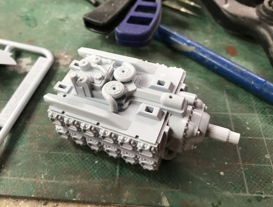
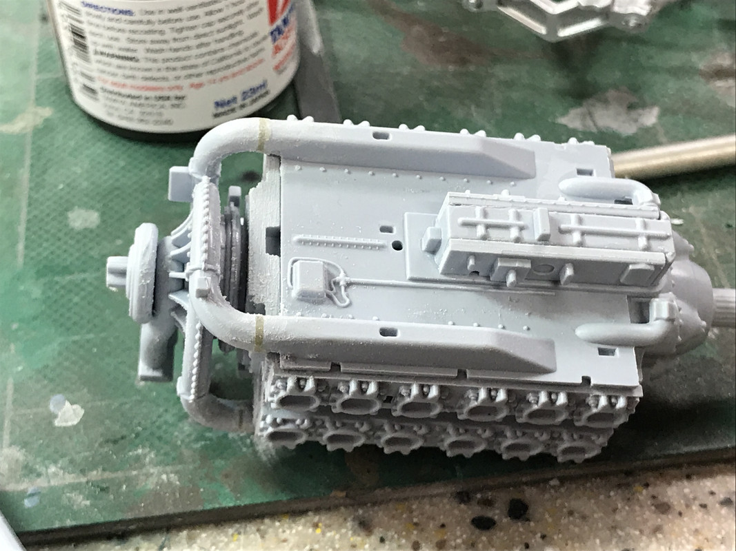
There is an Airfix operation to put a motor in this large engine block to spin the prop, but I chose to not do this. I did make sure that the prop shaft is lubricated (Vasoline) so the prop will spin freely.

Between the inner framing and the mass of the plastic parts, the engine block is quite solid. Most of the parts fit together perfectly after routine parts cleanup, but the junction between the supecharger induction pipes and their block attachment had a significant gap. I filled this with a combination of Bondic for the larger gaps and Tamiya filler for the lesser.

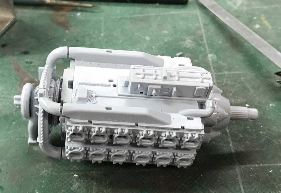
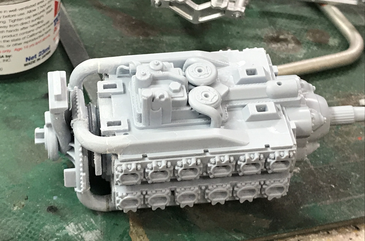
This is the engine bottom. Even here, you apply two separate pumps. By leaving the entire front skin off, a lot of these details WILL BE visible.

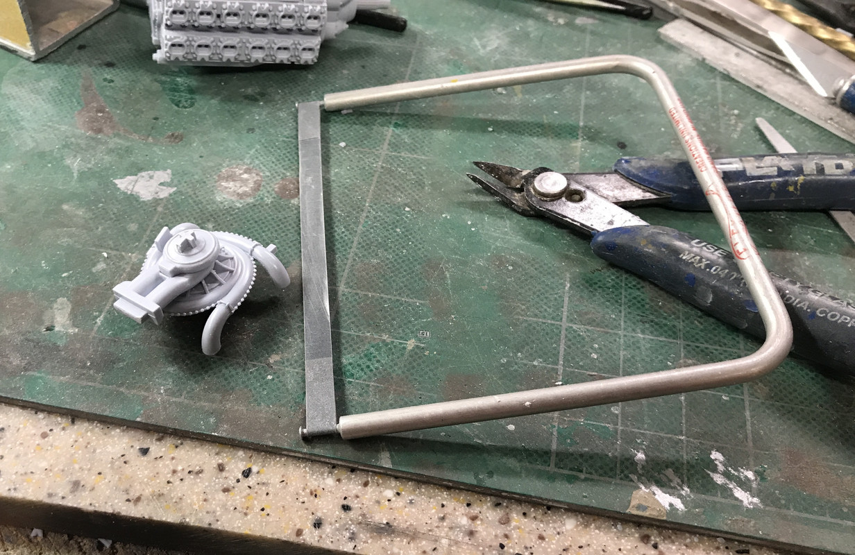
The supercharger is a model in itself with five parts. I used a lot of different sanding devices including a neat powered micro-sander I got from MicroMark. I bought that specifically to clean up resin prints. But another very useful one is the Flexi-sander which is superb for sanding round surfaces such as the induction pipes from the supercharger. By being a soft band it comforms to the curves and gives a great finish.

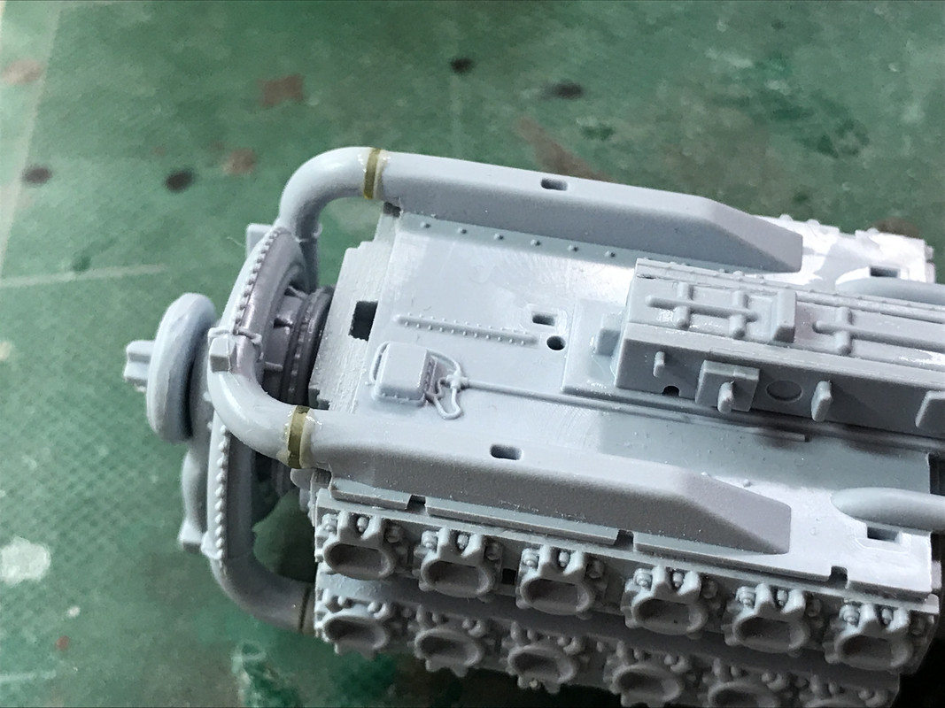
Here are the gaps in the induction system. Two were very large and two were more manageable.

The big gaps were too large for typical fillers so I turned to Bondic. You put it in a layer, harden it for about 5 seconds, put in another layer, and so on until the gap is closed. It's quite hard, much harder than styrene, so you have to sand accurately. If you concentrate on the filler you will get it right. If you need to, apply some masking tape to the styrene from affecting too much styrene.

Here's filled, but not sanded.

And after finishing:

The next step is to install the engine on the airframe before adding any more piping (and there's a lot), but before that it needs to be painted and detailed a bit. While the plans call for black, I'm going with green. It seems all the pictures of extant engines are a nice British Racing Green. Besides, the engine will be fully exposed and, since it's the most interesting part (to me) of this aircraft, the engine's going to be green.

Another clue that this engine's valves are different is that the induction and exhaused enter the side of the block, not the top.

  • Member since
    March 2012
  • From: Louisville, KY
Posted by Builder 2010 on Friday, February 14, 2020 5:20 PM

Didn't get much done today. Wrestling with my 3D printer. It was a draw.

Got the first coat on the Saber.

  • Member since
    March 2003
  • From: Virginia
Posted by Wingman_kz on Friday, February 14, 2020 9:01 PM
I didn't realize this kit had been out this long. For some reason I was thinking maybe 3 years since it's release. Been on the fence about whether to purchase it or not. Then the Hellcat was released and I went with it. I'm really enjoying seeing what you're doing here. Gonna have to start saving for this one I believe. I like the look of this aircraft. Will be watching with interest. Tony


  • Member since
    May 2013
  • From: Indiana, USA
Posted by Greg on Saturday, February 15, 2020 8:31 AM

Builder 2010
I have not had flash problems. The parts are real clean, almost up to Tamiya standard. Ejector pin marks have been minimal (so far).

Thank you for answering my question. I found a decent price, I might just  and give in after all these years and buy one.

It's good to hear your missing sprue issue was dealth with by Airfix directly.

Thank you for showing the fit issue at the exhaust pipe joins and what you did about it. I have way overengineered problems like that, I learned something.

Please keep this thread going, it is very interesting.

  • Member since
    December 2018
Posted by Ted4321 on Saturday, February 15, 2020 10:36 AM

This is awesome.  It's builds/WIPs like this that make me want to get to my bench more than I already want to.

I just stumbled upon this thread this morning and read all the way through.  Great work on the railroad and with the 3d printer.  Between you and me, this is way better than a magazine article. 

T e d

  • Member since
    March 2012
  • From: Louisville, KY
Posted by Builder 2010 on Wednesday, February 19, 2020 6:22 PM

Thanks guys! Correction: it was the intake lines that needed the filling. I like magazine articles too and have been writing them. Magazines have greater distribution than people who read my threads on the various forums on which I contribute. Depending on the models I'm building I post on a bunch of forums: for plastic it's WorldWar2aircraft.com and FSM and for train stuff it's O'Gauge Railroading's forum. I used to also contribute to WorldAffairsboard.com, but their picture posting is even more onerous than it is here. The easiest are OGRR's and WW2's.

The fuselage parts arrived from Airfix yesterday. So the model is now capable of actually becoming an airplane.

Building the engine has been just what I wanted. I also found some good photos of a Saber (albeit cutaway) which is why I'm painting mine green. I got the engine installed and lots (although not all) of the piping. People always say I'm "patient", but I'm really not. I am persistant. I don't give up, but I do make mistakes by rushing. If I do anything wrong (and I do a lot wrong... just ask my wife) is wanting to glue something together before the paint is dry. I do that too many times to mention.

The ignition wiring is sort of an orange tan so I mixed some of that. I needed to make a filler piece between the port side ignition distributor and the tubing for the spark plugs. I made it out of a small piece of 1/16" aluminum. It was caused by the harness not quite fitting tight enough to the block.

I picked out some bolts to use the Molotow pen on. Again, I probably shouldn't have handled it so quickly because it wasn't completely set. I didn't glue the front harness in yet when I took this. It was fitted just for the picture.

The engine has no weathering yet. I'm going to do mild weathering. I want this plane to be almost factory fresh, not a beat up hulk. It's how I do it. I have to do some more very fine back-painting to cleanup the black taping around the cross-engine ignition harness.

The engine truly is a model unto itself with almost 100 parts for it alone.

  • Member since
    March 2012
  • From: Louisville, KY
Posted by Builder 2010 on Friday, February 21, 2020 6:13 PM

Work continued on the superb Saber...

Finished all the topside appliances and piping. You have to pay explicit attention to the instructions. They WILL show you exactly where the start and end of the tubing goes, but you may have to massage it a bit to get it to settle in. The two intertwinning ignition harness is an excellent example of this. I had to use Bondic to get the lower junction points completed. I know I've mentioned Bondic before, but it's worth repeating. It great to have something that cures rock hard in 5 seconds and doesn't require additional chemistry like CA and accelerator. I still use CA since Bondic doesn't work on junctions where the UV light can't get to the resin. I changed the 2016 (2) batteries recently and it's brighter and cures faster. I went back and retouched the harness to make the color transitions as crisp as I could make them.

Some of the added details were very annoying. One in particular was an apparent throttle linkage that glues to too holes in the firewall and also glues to the supercharger. It probably took 20 minutes to get this thing in place. The lugs were slightly larger than the holes so I had to fix that. iIt was just an awkawrd location and the part should have been installed before the engine was installed. And as you know, the more you fuss with something, the more you screw up the paint, and risk breaking other stuff while you're manhandling the model.

But persistance paind off and it finally settled in so I could apply liquid solvent cement. So now the entire entire top is decorated with appliances and tubing. 


The other side:

Up next is all the piping and stuff on the bottom. Being a water-cooled engine, all the bottom stuff is about feeding the radiator which sits prominently below the engine. This engine produced 2,400 hp which was one of the strongest during WW2 and required a lot of cooling. Just for comparison, the F-35 produces 45,000 hp from a single F-135 turbo-fan jet engine. One of the biggest challenges faced in designing the STVL F-35B was creating a clutch to engage the lift fan that could repeatedly engage and disengage 45,000 hp without disintegrating and do it for 2,000 hours between major overhauls. It was a daunting challenge for Rolls Royce. They did it! The Harrier didn't have this problem since all they did was rotate the thrusting elements to go vertical like the F-35's tailpipe. But the lift fan was a totally different animal and needed to be fully enclosed so the aircraft could also do Mach 2.

  • Member since
    March 2012
  • From: Louisville, KY
Posted by Builder 2010 on Monday, February 24, 2020 7:58 PM

Work begins on the engine's bottom regions. The model wasn't very stable upside down so I cobbled together a holder to support it well when upside down. Some scrap ply and two piece of 1/4" square strip wood did the trick. I used CA to hold it together since I needed it "right now" and didn't want to wait for wood glue to dry.

Here's the airframe on the stand. It works!

It had to be stable because the piping that had to go in was a real bear. There was a four pipe manifold, with two being on one piece and the third added. This got glued to the firewall with two of the pipes and their manifold setting in a rectangular slot and that third pipe going into a round hole below it. The other end with three pipes just float there to be added to the radiator. Then a fourth very curvy pipe tied into the manifold on one end and wound its way underneath one of the intake pipes to settle into the engine way out of sight. After these were in, a two-piece injection system went in to the top of the supercharger intake pipe. YES! This engine did not have a carburetor. It was fuel injected.

This picture attempts to show these parts. They're black and they don't stand out, but trust me, it was quite a challenge to get them all settled into their proper locations.

IMHO it would be criminal to close up all this detail with the skin. As it stands, most of the cockpit will be out of sight. The car door version offers a little more viewing of the interior. The teardrop canopy version basically closes off everything.

I assembles all the radiator and induction parts that I could based on the instructions so I could paint them in their assembled condition. It calls for flat aluminum. The induction pipe has a straight shot right into the injector's throat. It would also have quite a ram-air effect. I'll be adding some more metallic effects and some weathering to these prominent parts.

BTW: Since I got the ultrasonic cleaner for the 3D printing, I'm using it regularly to clean my airbrushes. It works great. I clean it with water, then IPA, and then drop it in the cleaner for about 5 minutes. It comes out sparkling and it gets inside as well. The nozzle comes out quite good. The two-part induction pipe add a minor seam which I filled with Tamiya fine filler. The instructions have a specific illustration showing the cross-braces of the intake bezzle set at 45 degrees. 

The baffle plate got airbrushed RAF medium Sea Gray which I bought with a full 4-color AK set for WW2 British aviation. I tried them on for fit in this image. There are water pipes that extend through those holes in the baffle. 

By tomorrow the engine compartment will be ready for a little weathering.

  • Member since
    March 2012
  • From: Louisville, KY
Posted by Builder 2010 on Tuesday, February 25, 2020 6:59 PM

The engine bottoms was completed today with the beginning of winging the beast. First up was the weathering of the baffle. I used Tamiya brown panel accent and then removed the excess with a Q-tip lightly dampened with low odor mineral spirits. Much to my dismay, the solvent removed some of the AK acrylic gray. It's not very noticeable and I'll retouch. I think I needed to seal the surface before applying the panel accent. After installing the baffle, which needed some enhanced gluing with some medium CA, I installed the induction pipe. If you're building this plane, apply glue to the induction pipe injector end before putting it in. It's almost impossible to get solvent cement to it afterwards.

Added to that are two coolant pipes that wend their way through the baffle and tie to the rectangular notch in the main wing spar on both sides. I needed needle nose pliers to twist the pipes after entering the baffle holes so it would orient correctly into the notches. It didn't go easily. I don't know where the back end of the pipes went after leaving the spar. Perpaps a cabin heater?

The radiator was partially glued together before putting it on the model. And then it's glued in place where you have to connect it to five points simultaneously: the two lugs on the front of the engine, the induction pipe, and then those two coolant pipes. It just took some patience to keep working it. I used solvent cement and then some CA to finish the job. The bottom and side panels went on with some light sanding so they fit between the radiator walls. When all was in place I went over all the ducting and radiator with AK Silver Buffing Cream that gave more of a metallic sheen to the surfaces. I then used Tamiya Black Panel Accent to pull out the details. Again, some paint got pulled and I had to touch it up. I did the same thing on the simulated grill surfaces on the radiators and after removing the excess I dry brushed it with the flat aluminum.

The arrow shows one of the most ridiculous pipes to install in the whole deal. These pipes (R & L) are the coolant inlets to the two water pumps put on many steps ago. The outside connection is a breeze being a squared off lug so it only connects in one orientation. The pipes had pins on their inboard ends that are supposed to drop into the holes in the pumps' center. The biggest problem was seeing inside. I had to keep maneuvering the model to get light to play inside so I could see where the pipes were in relation to the pumps. They seemed like they wouldn't fit, and then, like one of those crazy bent wire puzzles, they just dropped into place. That was after about 10 minutes of fussing with them.

Here's another view showing just how difficult it was to see if the pipes were actually entering the pump. I was concerned to get it there not just to be prototypically accurate (you really can't see the darn thing), but to make sure it was glued on both ends for security. It was just as hard to get a picture of it as it was to see it. When you see how inaccessible those innards are, it makes me wonder why I bothered painting it at all.

The last radiator pieces was the surge tank that sits in front of the engine. It too ties to the radiator and to the ends of the remaining two pipes. These tanks are found all all the merlin powered craft too. The radiator set up on the Typhoon is pretty compact and very intuitive and required less pipe runs than those in Mossies, Spitfires and other water-cooled craft.

So here's the entire engine installation. I don't think I'm going to add any smaller wires unless you guys talk me into it. Enough is enough.

The Saber weighed about 2300 pounds and then you add the cooling system and coolant. It explains why the wings are as far forward as they are. Center of Gravity would be far forward.

With the engine in it was time to start on the main wing. This was an exciting milestone. The bottom wing glues to three points under the fuselage (the firewall bottom and two large lugs reward) and then to the entire length of both wing spars. Before you glue it on you have to attach the upper mounting point for the main gear.

I went through the entire instruction sheet before starting to highlight every page having an optional step based on the version (D) that I'm building. My version has these variables: landing gear extended, engine and radiator exposed, late version with full invasion stripes, rockets and external fuel tanks. This choice required drilling specific holes in the wing for the rockets, tanks and i.d. lights specific to this plane.

I glued the fuselage connections first and clamped it so it set up. I used tube cement since I wanted to be sure that it bridged any gaps. You can't really get into there with CA after its together. I then clicked into place the spars. They do align pretty well... good engineering. I used tube cement to hold in the gear base and then solvent cement for the rest. I clamped it so it can dry properly overnight. The rubber band is applying pressure to the top half of the expansion tank. The piping was putting some negative bias on this while it was drying and it needed some help.

 The next steps involve a lot of inside wing constructions before the top skin goes in: more ribs boxing in the two gun bays and the wheel wells, plus four Hispano 20mm cannons, ammo boxes and feeds, and fuel tanks. There are access hatches that can be open for the guns, but the fuel tanks will be forever hidden unless I cut over the wings just for fun. Without a doubt, this is the most complex plastic model aircraft I'll ever built. You absolutely have to pre-fit everything, and even then, you'll get a few wrong.

  • Member since
    March 2012
  • From: Louisville, KY
Posted by Builder 2010 on Wednesday, February 26, 2020 6:00 PM

Wing construction continues...

The inner wing has a network of ribs and spars that interlock with each other with cross-lap joints. They really snap into place and shows some good engineering. The first group consists of three bulkheads: wing root, mid wing supporting landing gear lug and mid-wing end. 

When I took this picture I didn't realize that the end ribs were reveresed. I'm not sure how I did that. I was attempting to be very careful with the part numbers and yet it was reversed. It is possible that it was an error in the instructions. Regardless, I caught it in time before all the glue had fully cured and was able to remove them and switch them.

The next parts with included a spar and rib subassembly required some clamping to get it nice and tight.

This piece nestled into the cross-laps of the existing parts. It was these cross-laps that showed my error. When I went to connect it to the outer rib, the cross-lap was on the bottom and unreachable. The part was upside down. To rectify this I had to remove both rib, R & L, and re-glue them in the proper location. No harm no foul. With this correction, the joints were made. I needed to add some clamping to ensure that the entire length was in contact with the lower skin. I also needed to ensure that ALL the ribs were nestled down completely. If not, the top wing skin gluing could be problematic.

The gun bays were covered in leather. It's told that it was to dampen the vibration when firing the 20mm cannons. It may also have reduced the chance for sparking. I don't know. If anyone knows, please comment. I mixed the leather color with Tamiya red brown, yellow and some more red. To apply the color to the bays required some masking.

After this dried I overcoated it with some clear gloss to provide a good base for further weathering. I wanted a surface that would not be damaged by the washes.

The gun bay frames are called out to be light yellow. I first painted them with flat aluminum, then applied some Microsol liquid mask to make some paint wear. After it was dry, I peeled the mask to expose some "bare metal".

All of this stuff will be nice and dry tomorrow. I have to paint the guns too. There are brass barrels available for this model, but with the shrouds you really don't see much of them; at least not enough to warrant the cost in this case. You are instructed to drill out the ends. I do that routinely anyway.

With all this interior framing, the wings will be very strong.

  • Member since
    March 2012
  • From: Louisville, KY
Posted by Builder 2010 on Thursday, February 27, 2020 6:20 PM

I was multi-tasking today, wrestling with my 3d printer and building the Typhoon. I got the gun bays almost finished. Finicky, but fun.

The framing fits in tightly and needed just a little shaving in its length to snap into place. I had inadvertantly installed the ribs that go down the center of the space BEFORE the framing, but luckily, glue wasn't set and I was able to pull them out, get the frames in a re-glue the ribs. I then gave it all a coat of AK Dark Gray wash. Also installed the framing for the flaps that went in easily and is stong.

The guns get hand-drilled out for the muzzle and did so using a 0.035" drill, which equates to the .9mm called out by the instructions. I airbrushed the guns on the sprue along with all the remaining flat aluminum painted pieces that I could identify since I didn't want to keep cleaning the airbrush. All the LG parts are this color except for a hydrualic accumluator tank which is black. When the top wing is on and the gun shrouds are in place, you will barely see any of the barrel. Even the muzzle will be buried behind the shrouding.

I went back and put another coat of the yellow on the ammo feeding drum, and then painted the black areas NATO Black. I went back and forth between black and yellow until I got it almost right. These parts are glued to the guns. According to Don at eModel.com, he said you needed to drill out the gun openings in the interior spar so the guns would fit. He was right. The guns themselves would fit, but there is a part glued on top of the barrel that prevents it from passing through. I drilled it with #25 drill held in a tap handle. I then glued the guns in place.

I painted the ammo in three steps. Brass first for the cartridges, brass mixed with clear red and yellow to make copper for the slugs, and then hand-painted the belting. I then went back and touched up, and finally added some panel line accenting.

I painted all of them, but then got only one ready to install before it was time to close up shop for the day. My wife has a rule. Work stops at five! No work on weekends or evenings! I stick by it and we get along fine.

I hate hand painting yellow. And the little ribs on the drums are not very distinct so it was a challenge to get it right.

Tomorrow the guns will be finished. There are some fuel tanks that go into the wings (although I don't know why since they're buried) and then the upper skin goes on. The model's getting heavy. There's a lot of plastic in it already.

  • Member since
    March 2012
  • From: Louisville, KY
Posted by Builder 2010 on Monday, March 2, 2020 6:31 PM

Very late start today, but did get the upper wing fully glued and started addressing leading edge finishing.

With a bevy of clamps, I used Testor's tube cement applied with a dental spatula to the flap and aileron spar, and the wing tip. 

After about 1 hour I pulled the clamps and everything was tight. I went back and added some solvent cement on some questionable areas, and the added more to the inter-wing areas like were the gun bays and wheel well ribs intersect with the skin. I added clamps to these places also.

After pulling the masking tape at the leading edge I did see some separation at the wing root. It was holding and strong, but there was a gap. I used Bondic to fill the gap, mainly because I can cure it so fast. I masked the area so the sanding wouldn't destroy too much of the leading edge detail. I used my MicroMark precision sander to quickly knock down the hardened resin and to remove the "over bite" where the lower wing extended out a bit from the upper wing. I had to be careful not to square off the leading edge with all the sanding.

I will go back and add a touch of Tamiya filler and do some restoration of the details. Here's the top wing without clamps or tape. It's quite solid. I've almost broken those guns sticking out about four times. Luckily, the Airfix plastic is pliable and didn't break or deform. I'll feel better when the gun shields are in place. If I had purchased the after-market brass ones, I would have broken them off from the receivers. Best that I did go that route.

While the wing was drying I started working on the fuselage side (that imfamouus Sprue M that was missing). First I cleaned up the sprue marks and then removed the front portions that will expose the radiator cooling system. There is a deep engraved line inside that helps you cut this correctly. I used the micro-saw to make the cuts. The vertical stabilizer is glued on as a separate piece. It has a broad gluing area, but I added a piece of styrene on the top edge to reinforce that especially if I have to fill that joint. There needs to be filling on those reinforcement plates at least. Those plates were added to later production Typhoons because the earlier models had the unfortunate habit of having their tails fall off. Makes it hard to control the airplane. The plates would be solid across their length so the joint isn't right.

There's some painting inside the fuselage; Nato Black in the cockpit area. I will do this tomorrow. Notice I already painted the inside of the tail wheel well using flat aluminum.

  • Member since
    March 2012
  • From: Louisville, KY
Posted by Builder 2010 on Tuesday, March 3, 2020 7:32 PM

Today was a good day: I got a new cutting pad. MicroMark had a sale with them at half price. It will enhance my picture taking.

Spent quite a bit of time finishing up the leading edge. First some Tamiya putty and then re-scribing the panel lines and drill out the now-missing rivets. I attempted to keep them in line, but occassionally slipped. It's just for effect and to hide all the sanding work that had to be done to bring the leading edge to form. I used a dividers point to mark the location and lightly drilled them with a #80 drill in a pin vise.

Then I installed the gun shields. You glue in the bottom half first aligning two extensions with an unseen rib inside the wing. After it set up a tad, you glue the top half to the bottom and into the wing leading edge. You can see that the gun barrels are now completely hidden for their whole length and painting them was an exercise in painting practice, but nothing else. I'm glad the covers are on because they're much stronger than the naked barrels.

I masked the fuselage for the Nato Black, but the masking also was superfluous since the demarcation line between bare plastic and black paint will be invisible when the fuselage is glued in place.

It was a quick air brush job. There was a little overspray, but again, not visible.

There's a couple of parts sandwiched in the fuze for the tailwheel: the wheel well and the tailwheel strut. The strut had two plastic pins trapped in a hollow lug on each fuselage side. It fit tight and was keeping the fuze from closing tightly at the back.

I decided the plastic pin had to go. I replaced it with 1/16" brass. I drilled out the lugs to accept the slightly larger brass. I also shortened the pin slightly to make the fit better. I tested it and it worked as designed.

So it was time to start gluing the fuselage onto the front assembly. It glues at the wing fillet, a little bit at the firewall and an arc at the rear cockpit area bulkhead. It seemed like it would be a troublesome fit, but it wasn't. I cleaned the paint off the wall so it would hold glue better. I first used tube cement, but had to go back and add some solvent cement and got a good joint.

The wing root fit was surprisingly good. The tube cement leaked out a bit, but it should be no problem to clean it up.

I ended the session fitting the right fuze side when I ran out of time. I was also continuing my battle with my 3D printer. I got success today, but changed three variables and don't know for sure which one or combination solved the problems I was having. More experimentation is warranted.

JOIN OUR COMMUNITY!

Our community is FREE to join. To participate you must either login or register for an account.

SEARCH FORUMS
FREE NEWSLETTER
By signing up you may also receive reader surveys and occasional special offers. We do not sell, rent or trade our email lists. View our Privacy Policy.