Greetings All!
My name is Russ, and I have recently gotten into making models using AutoCad and 3-D printing. It started with a display I made for my dad of the planes he flew during his career in the United States Air Force.
“A Career in Flight” – 3D Printed 1/350 Scale Aircraft Display (Work in Progress) - http://cs.finescale.com/fsm/modeling_subjects/f/2/t/157366.aspx
Through this post, I met Ron, and we have collaborated on several “projects” that are posted elsewhere on this Forum, including:
1/144 Scale Luscombe 8A Silvaire - http://cs.finescale.com/fsm/modeling_subjects/f/48/t/158982.aspx
1/350 and 1/144 Scale Cessna 310B - http://cs.finescale.com/fsm/modeling_subjects/f/48/t/159017.aspx
1/350 Scale Gulfstream IV-SP - http://cs.finescale.com/fsm/modeling_subjects/f/48/t/159041.aspx
1/144 Scale Spartan 7W Executive - http://cs.finescale.com/fsm/modeling_subjects/f/48/t/160518.aspx
1/144 Scale McDonnell F-4K Phantom FG.Mk1 and F-4M Phantom FGR.Mk2 - http://cs.finescale.com/fsm/modeling_subjects/f/2/t/160249.aspx
1/144 Scale Lake LA-250 Renegade - http://cs.finescale.com/fsm/modeling_subjects/f/48/p/162598/1772871.aspx#1772871
1/144 Scale Cessna 421C Golden Eagle - http://cs.finescale.com/fsm/modeling_subjects/f/48/t/162600.aspx
1/350 Scale Aircraft Diorama - http://cs.finescale.com/fsm/modeling_subjects/f/19/t/161594.aspx
This thread will show the process used to make a 1/350 Scale model of the McDonnell Douglas A-4 Skyhawk.
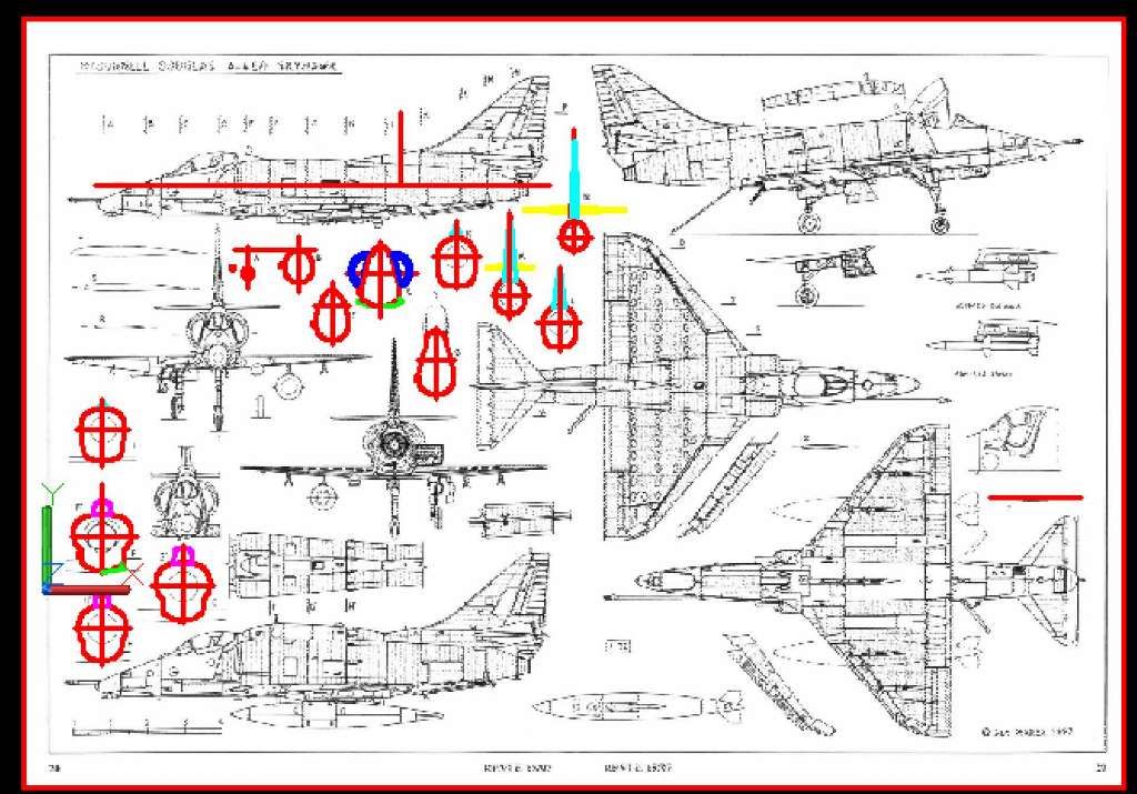
As usual, the first thing I did was search the internet for plans, which I then downloaded, imported into AutoCad, and scaled to size. For this model, I found two sets of plans, one of the A-4F/E by Jan Merek, and another from Aviation News showing the A-4E, A-4M and the TA-4F. I started with the Merek plans because they are of slightly better print quality and have more cross-sections.
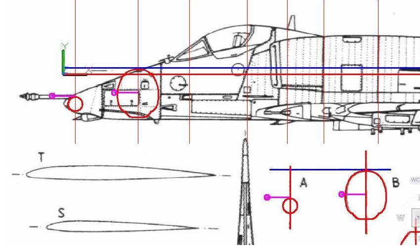
The next thing I did was trace the outlines of the airframe cross-sections, as shown below.
The next step was to copy the sections to their proper places on the side view. In the image below, you can see that the reference lines on the sections didn't always line up with the reference line on the side view, and I had to move them either up or down slightly. In a few cases, the section's size was off a tad (the lines at the top and bottom didn't match). In these cases, I moved the section so that the bottoms matched, and scaled the section up until the tops matched too.
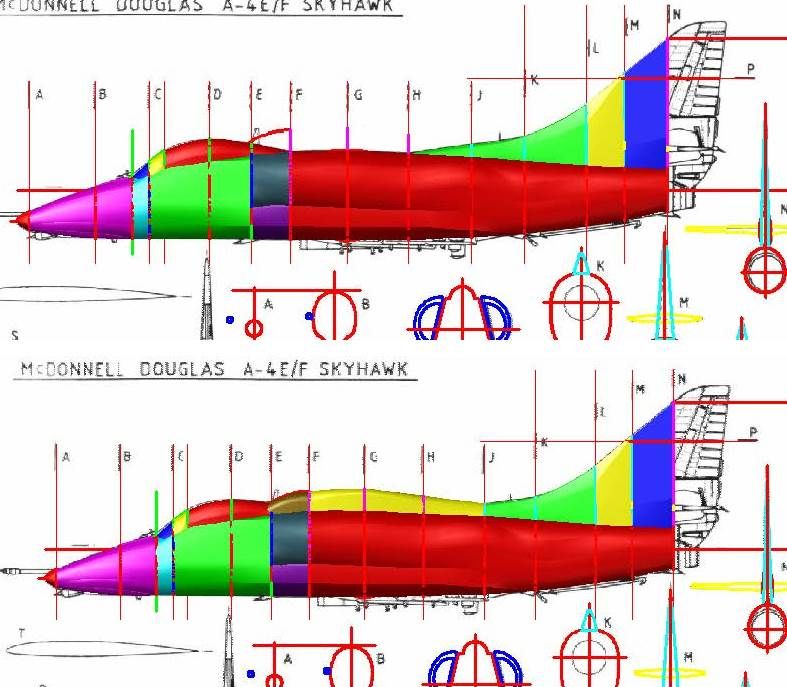
The image below shows it after I have copied all of the sections to the side view, and modified them as needed. Notice that on some of the sections I broke them into 2 different sections. This is because I have found that splitting the parts up gives me more control of the shape, and I can later join the shapes together.

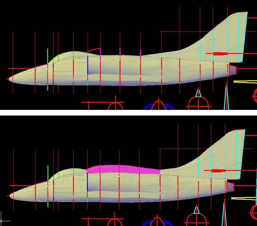
With the sections in position, I rotated the sections 90o about their vertical axes. I then used a combination of Loft and Extrude Commands, to turn the sections into “solids”. The image below shows all of the various solids (except the forward part of the engine cowling section on the right side) that I made from the sections. Note that I had to add 2 sections (between B & C and between C & D) to get the shape right in these areas, and I had to adlib the nose. The top image shows the E without the hump and the lower image shows the hump, that according to the Merek plans was on the A-4F, and according to the Aviation News plans was on the A-4M.
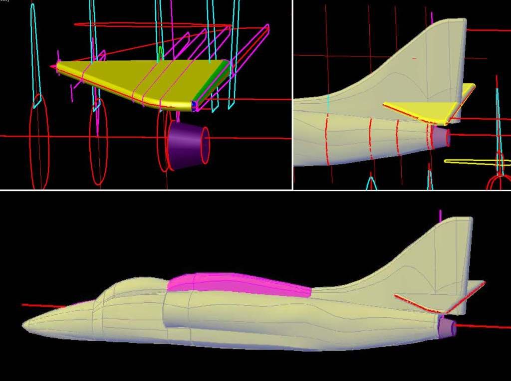
Because the model is in 1/350 scale, I had to make the tail thicker than it really is so that it will both print, and be durable enough to survive handling during cleaning, painting and assembly, as well as shipping. Although it is difficult to see, the images below show the tail before (top) and after (bottom) I modified the sections to make the tail thicker. Note that the port side horizontal stabilizer has also been started. The “solid” part was generated using the sections, the outline is from the top view that I have traced copied and rotated. The exhaust nozzle may also be seen.
At this point, I joined the airframe parts and tail together. I also joined the hump parts together, but did not join them at this point. This will be done later to make multiple versions.
The next set of images show the construction of the stabilizers, which, like the tail were made thicker than the plans show. In this case I did one side than used the mirror command for the other side. The lower image shows it after I have joined it to the airframe.
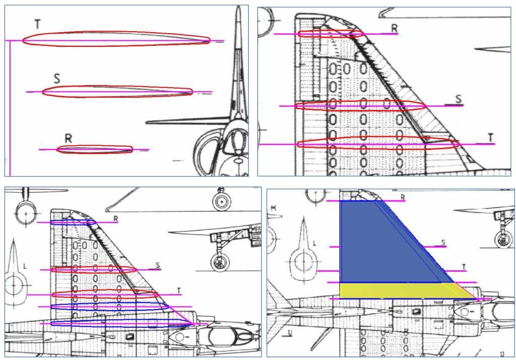
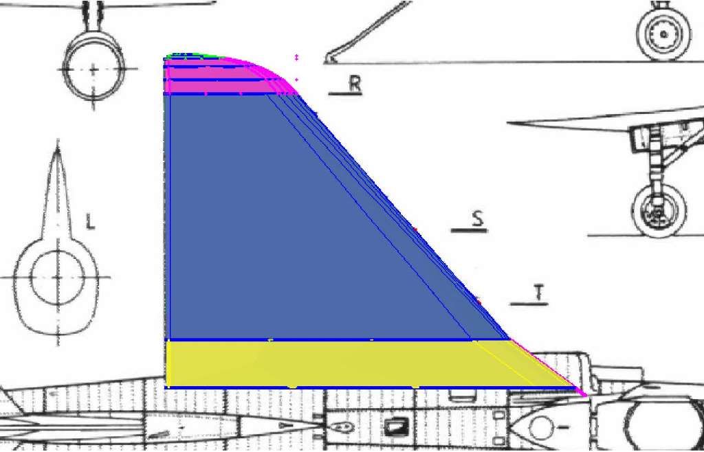
Next, I did the wings. In the set of images below, you can see the tracings I made of the wings (top left). Note that I made the aft ends thicker than the plans. The image at top right shows the sections copied to the wing on the top view. Note that the alignment isn’t perfect and required slight modification. Also, in order to actually make the wing, I needed more sections than provided, so I copied the T-section and modified it, to create the blue sections shown in the lower left image. The image at lower right shows it after I rotated and joined the blue sections.
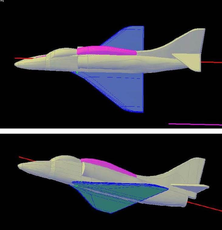
To make the tip I copied and scaled section R to match the top view and lofted them together, as seen below.
At this point, I joined the pieces together and mirrored it. I then had to copy it to the airframe side view and rotate it to the proper orientation. I later joined them to the airframe.
With the basic shape completed, the next thing to do was to start detailing. Stay tuned…