SEARCH FINESCALE.COM

Enter keywords or a search phrase below:

Trumpeter 1:32 F-105G Wild Weasel Build Thread

15548 views
91 replies
1 rating 2 rating 3 rating 4 rating 5 rating
  • Member since
    March 2012
  • From: Louisville, KY
Posted by Builder 2010 on Friday, May 17, 2019 6:01 PM

Thanks. Just hope I can get them both there in one piece.

Short session today... Got the dive brakes painted. Exterior was shot with Tamiya Smoke so the metal shone through. I'm probably going to pick out the fasteners a bit more with some wash or another.

Interior was painted almost fully with Burnt Iron. I'm going to pose the model with the dive brakes in landing position. There were two more body pieces that went on to fill out the 360 degrees of body to which the dive brakes connect. These get painted camo color.

Last thing I did which took most of the 2+ hours I spent was presparing the ordinance load out. I've chosen an all-missile scheme with four Shrike (AGM 45a) and two Standard Missiles (AGM 78) plus the huge center-line fuel tank. All of these parts are not finished. I chose to glue the halves together with all the sprue nibs still attached and after fully cured go back and finish off the seams and curves. It will dry all weekend and I'll do the finish work on Monday. It took a bit of studying the instructions to fully understand what adapters went on what pylons to affect the correct configuration.

The missiles will all be painted gloss white and get detailing and decals before assembling to the adapters. The pylons and adapters get bottom color. The fuel tank, according to pics I have seen is dark green upper and bottom color on the lower half. All pylons will be attached after most of the painting and masking is finished.

  • Member since
    December 2005
Posted by Jor-el on Friday, May 17, 2019 11:40 AM
Still an inspiration, as well as informative. Good luck with the show. Carl

Growing old is mandatory,

Growing up is optional!

  • Member since
    March 2012
  • From: Louisville, KY
Posted by Builder 2010 on Friday, May 17, 2019 8:42 AM

For some reason yesterday's post disappeared, so I'm posting it again.

No Problem… It just shows you're paying attention.


First of all, when we were talking about how big this beast is, here it is hogging all the space on my work table. Notice the excellent organizational skills at work.


Lots of odds and ends today. The gear cured well and are strong. There is some side to side sway, not due to the gear, but to the inherent flexibility of the upper wing skin to which the gear is affixed. I did read where someone soldered the gear to a brass plate and installed that into the wing to give more stiffness. Overkill! The model's not a toy and will not be handled very much.


There were two plastic levers that flanked the base of each main strut, and they were a bear. it was due directly because the gear is metal and the levers had to be CA'd in place. There was also not a very clear attachment point. The plastic gear would have had a specific place to attach. The first one went on okay. The second one broke in half due to the amount of force I was putting on the tweezers. I fixed that by adding a piece of 0.032" brass rod to replace the skinny part.


These levers pull the small bottom gear door closed behind the gear when it's retracting. those gear doors will go on after painting. I'll paint the underside color for the doors while they're on the sprue. They'll go on last.


I added the hinge closure pieces on the nose cone. All of them had to be shaved down.


The gun outlet fairing is stainless steel on this plane. Some restored museum planes have this panel painted body color. It is not. So I masked off the gun compartment and sprayed it with rattle can Tamiya Silver Real Metal. I didn't like the shine so I went back and applied some of the tube AK Interactive metal which I then burnished it with some paper toweling and brought the shine up.


This will all be masked off so it will be nice and shiny when done. I will probably add just a bit of soot from the gun exhaust.


While I was working on the nose cone I broke the other elevon off and did the same repair with the 1/8" brass tubing. The original design simply was too fragile to hold up. I added the intake splitters. I found that these are painted body color so puttin them on now was prudent. These separate the boundary layer air from the intake air.


There was a little bit of opening at the back edge which I filled with Bondic—I didn't want to wait until filler dried.


I started adding some of the doodads that spring up all over this plane. Since the Wild Weasel was a special plane with a special assignment and has a lot of antenna. The side bulges onto which the little added bulges sit was an ECM pod that normally was underslung, but in this case they split it in half and permanently mounted each half on the fuselage. The front, back and bulges get painted black.


I painted the dive brakes which extend out like flower petals Tamiya Real Metal. Tomorrow I overspray the outer surface with Tamiya smoke to make it look like titanium, and the inner surface with the burnt iron color like I did with the jet engine. These too will be added after the body painting is completed. They too will be delicate.


I want to temporarily glue the gun compartment panel so I can paint it with body color while doing the rest of the model, but it didn't fit. The Vulcan front support was sticking out too far. This was caused by the Eduard PE appliqué adding more thickness to the back wall. I scraped and filed the support, but couldn't get it low enough. Finally I relieved the inner face of the compartment door. Eduard has another PE set for this plane with some more exterior details including a PE gun door. It would have been much thinner and probably would have fit. There was also some terrible ejection pin blemishes that had to be removed too since the door is going to be posed open.


There are cooling slots on the outside of this panel, but nothing on the blank inside. I'm thinking of drilling them out...More AMS.


As an aside... this Saturday is the Military Modelers of Louisville Club show. I've missed it for years, but this year we're around and I'm going to enter my Missouri and Essex in the contest just to see if they're as good as I've been telling people they are. I worry about bringing them since they are really delicate, but the Missouri's been sitting on the shelf for almost 7 years so it's time to let others see it. For the Essex the only thing I worry about is all the little planes breaking loose from the flight deck. I'll bring some CA with me and a tweezers to replace any that want to "take off."


The Missouri's pedestals are not as broad as the Essex's so the model can oscillate from side to side. I stick some dense foam pads under the hull to firm it up so it doesn't move. The Essex is very solid and doesn't need anything. They're both heavy with the bases and the plexiglass cases. In both models I will tape the cases to bases so nothing moves.


Just to refresh your memory, here both are sitting nicely on their shelves.


  • Member since
    March 2012
  • From: Louisville, KY
Posted by Builder 2010 on Wednesday, May 15, 2019 3:33 PM

In a short session today, I got the main gear piping complete and attached the main gear to the wings.

To start I painted and attached the main gear landing lights. The first one wanted to be a pain since it's a difficult shape to grab with tweezers. I put a drop of thick CA on the strut, pick up the piece with the tweezers, and then lose it a few times. When I would finally get it in place, the CA would have already set and I'd have to do it all over again. For the second strut I wised up and used a pic-n-stic parts holder to grab and place the light. It came out much cleaner. If I had a 3rd one to do, I have two good ones.

I used High E Guitar string for the solid brake lines and some very small gauge wire insulation for the flexible portions. I secured all this to the strut using gel CA, thin CA and then some "clamps" using wine bottle foil. I found that after cutting the thin strip of foil that I soaked the piece in acetone to remove any ink or lacquer on the foil. It makes it much easier to attach using CA.

I made the landing light electrical hookup with the same thin copper wire with its insulation. 

I had to clip the end of the plastic retraction piston rod to make it a tad shorter so it didn't interfere with the locking leg on the strut. I then mixed up a small amount of J-B Weld and epoxied both gear into position. J-B Weld takes a good day to fully cure so the model was set aside for today's session. Sorry about the camera jiggle.

Here's a closer look.

Tomorrow I'll put the gear doors in place, and put on any antenna that can be plane color. A lot of them are painted black so I may attach them after (or not) depending on how much they will interfere with masking the camo scheme.

  • Member since
    March 2012
  • From: Louisville, KY
Posted by Builder 2010 on Tuesday, May 14, 2019 6:33 PM

Glad you like it!

Today got the cowl front finished with the adding of the HUD, masking and then airbrushing flat black. I'll go back and add some more Eduard stuff that sits on the top of the instrument panel cowl and the lensing for the HUD. They're delicate so they'll wait until I can put them on without wrecking them later. I used a piece of styrene to close that gap on the right side and then used CA and filler to finish it off.

I put the nose cone in place with tube cement. I put in the internal framing, but didn't include any of the radar since the cone is staying closed.

I also glued on the resin jet engine cooling intakes that flank the fuze sides. These scoops were added to the F-105 series later in its life to correct an engine overheating problems. The kit's scoops were two-part affairs with a seam that the resin parts corrected.

I finished all the sanding of the filling so the ship is almost ready for paint...

The kit's wheels hinted at the holes, but they weren't open, so I drilled them all out starting with with a centering mark with the point from a dividers, then a small starter drill and finally a drill size that matched the wheels' openings. I added some Tamiya Panel Accent to give them more depth.

I made the oleo slides with Bare Metal Foil. I still have to add brake lines and electrical wiring that goes to the landing lights that sit on the struts which I have to add also.

So here's the plane sitting on all three wheels. The mains are not glued in. I will have to use epoxy (J-B Weld) since the mains are brass and will be sitting in a styrene socket.

I have a load of details to add to the fuze before getting ready to paint. So we're moving right along. That is one big-ass plane. It was almost the size of B-17 with 10 less crew and 3X the ordinance.

  • Member since
    December 2005
Posted by Jor-el on Monday, May 13, 2019 9:21 PM

Good to see your progress. Like I said before, your efforts at overcoming this kits problems will help those of us attempting to duplicate your efforts.

Carl

Growing old is mandatory,

Growing up is optional!

  • Member since
    March 2012
  • From: Louisville, KY
Posted by Builder 2010 on Friday, May 10, 2019 8:46 PM

Back to work...

First up was finishing up the main wheel wells in preparation for joining wings to fuze. Instead of using the AK "real metal" cream on a finger tip contained in a surgical glove, becuase of the angle, I just brush painted chrome silver, black and white to pick out the details. I then added some Tamiya Black Panel Accent to dirty up the wells a bit.

I airbrushed Vallejo Air White the insides of the air intakes on the wings themselves and the triangular trunks that lead into the plane on the fuze.

I joined the wings using tube cement and held them them tight with some strategically place clamps and rubber band.

While the wings were curing, I started building the vertical tail. It too had the last Trumpeter-style PE hinge scheme which went together easily with this part. I then CA'd the PE hinge into the box on the one side of the vertical stab and applied tube cement to the edges to bind the two halves together caputuring the hinge rod in the process. Just then I decided to check "How does the tail get attached to the fuze?" The have to be assembled ON THE FUZE! There's a rectangular open tab on the fuze that is caputured by a corresponding tab on one half of the vertical stab AND THEN YOU GLUE ON THE OTHER HALF. I quickly was able to rip the stab apart and then reassemble it with the fuze attached. It was a close call.

Here's the instruction showing the "sandwich" with the fuselage tab. 

Because I never encountered a tail join like this, I had just proceeded gluing it up as I would normally do. Luckily, I looked at that rectangular tab and wondered how it went together and then reviewed the instructions with more concentration.

Here's all the flight surfaces in place.

Some of the joints needed a bit of filler, particularly the vertical stab to fuze joint and a but to tighten up the main wing joints.

While I was sanding the nubs on the vertical stab... I was going to sand them when the stab was glued together, but now that meant sanding them when it was attached to the plane...I broke off one of the elevons. I was dubious about the plastic pins that snapped into the fuze being strong enough to handle and I was proven right.

Because of the way the pin snapped in, the stub was not removabale. I decided to drill it all out to 1/8" and use a piece of brass tubing for the new joint. 

This was CA'd into both peices. The joint won't rotate, BUT IT WON'T COME APART EITHER.

The last thing I did was glue the instrument panel cowl in place. The entire forward instrument area will be painted flat black on Monday. The gapping on the left side is more residual difficulty presented by the Eduard "lifting the cockpit" issue. I will fill it with some styrene before painting it. There's a bunch of Eduard PE instruments that go onto the back edge of the instrument cowl.

I had built a Revell model of this plane back in the late 50s, early 60s and never realized just how big it was. The F-105G is 60 feet long!

  • Member since
    March 2012
  • From: Louisville, KY
Posted by Builder 2010 on Thursday, May 9, 2019 6:18 PM

Thank you very much. It was greatly appreciated. Got back this afternoon. Flying through Phoenix is always a bit stressful. Today was more so since the plane out of Portland was a hour delayed due to inspection regimen resulting from a bird strike the night before. I was the last person on the Phoenix connection. Our bags found a place in the overhead at row 20 and I found my seat at row 8. A logistics problem to be solved... I was able to quickly get back to the bag row before the aisles filled up with all the people getting their bags. Meanwhile, we had purchased the early bird upgrade to give us a lower position in the SW boarding line. It didn't do any good this time.

  • Member since
    December 2005
Posted by Jor-el on Tuesday, May 7, 2019 6:00 PM

Our condolences, never good when a loss happens, friend or family. Safe travels. OBTW, WOW! Looking good


Carl

Growing old is mandatory,

Growing up is optional!

  • Member since
    March 2012
  • From: Louisville, KY
Posted by Builder 2010 on Monday, May 6, 2019 7:09 PM

Thanks... I definitely will continue. Today started with sanding and finishing all the fuze filled gaps and then using the razor saw and a 0.021" drill to re-engrave the panel lines obliterated from the filling/sanding and open up the rivets. I then built the leading edge slats, and in typical Trumpeter fashion, they were a pain the butt to build.

Trumpeter uses some thin PE hinge bodies and steel rods to form the moving flight surface side of the connection. I find it impossible to build these without first gluing the rods in place on one half of the surface using medium CA and accelerator. I then joined the surfaces together. Because of the hollow shape of the slats, it was annoying to hold the leading edge together and get the glue to hold. After I took these pictures I cleaned up the leading edge so the seam was no longer visible.

The alierons also had the steel pin and PE hinge, but in this case, it did not want to engage with the wing proper so I eventually glued both in place in the neutral position. I placed the slats in place in their slots on the wing and fastened the hinge PE to the wing with CA. The flaps' axle just sits in an elongated track on the wing extensions waiting for the upper wing to be glued in. I used tube cement to hold the wings together, and then went around with solvent cement applied from both the inside—where I could access it with a long brush—or carefully on the outside and let the cement wick into the joint.

After it cured a bit, I started to sand the edges and add some filler where needed (not much), and then added some CA into the big joint on the leading edge near the intake scoop, cured with accelerator and then sanded again.

The tabs that hold the flap hinges needed some extra care since they were a bit springy. I used solvent cement held with some tweezers and even used some med CA to keep it together. If this opened the flap would fall off the airplane.

There's some interior green touchup needed in the wheel wells. The leading edge slats are movable (sort of), but the flaps work very well. Considering the size and weight of this plane, those were really small wings!

The last thing I did was build the elevons. These are just two-piece affairs that went together without complications. They will snap into their respective holes in the fuze, but I'll do that after the main wings go one... which, BTW: is the next step.

But, work will have to stop until Friday. A very old, and dear friend passed away suddenly on Sunday morning. They live in Portland, OR, having moved there (like us) to be near grandkids. It's an all day trip to go from Louisville to Portland, so it travel tomorrow, funeral Wednesday, and travel Thursday. 

  • Member since
    December 2005
Posted by Jor-el on Sunday, May 5, 2019 8:40 PM

It looks like you're back up to speed. Showing your stuggles and successes is a big help, at least to me. I hope you continue.Geeked


Carl

Growing old is mandatory,

Growing up is optional!

  • Member since
    March 2012
  • From: Louisville, KY
Posted by Builder 2010 on Friday, May 3, 2019 6:38 PM

Thanks John. So it's a passive device? That would mean the wiring would only be for the lights themselves, I suppose.

Should have had a longer session today, but it ended at 3:30 so I could pick up grandson at a friend's. I got all the fuze seams sanded and then added filler to only a few places. I'll have to re-scribe some panel lines what roll over the seam curves. I also glued on the tail cone using tube cement to fill any gaps. 

I then assembled and added the tailhook. It just get's painted bottom color. There's a hydraulic piston buried underneath that will hard to chrome (and hard to see).

Lastly, while the filler was drying, I started on the main wings with installing the speed breaks. Since they were separate parts, Trumpeter suggested you can have them extended 15° or flat. I decided that the plane had just landed the speed breaks would be up and besides, it's more interesting. I then assembled the flaps which also can be actually movable. It has that silly metal bar Trumpeter hinging which I find dubious at best. The left flap had its edges filed smoothe, the right one will be finished next session.

Next session, I'll finish up the fuze surfacing and get back on the wings. 

  • Member since
    December 2002
  • From: Northern California
Posted by jeaton01 on Friday, May 3, 2019 12:15 AM

The build looks like it is going well, I keep looking in.

The box below the lights is actually a radar reflector.  It helped the controller in front of the radar screen on the ground see the airplane on radar as he gave commands to the pilot on a GCA approach (Ground Controlled Approach).  Why the F-105 had it and other similar aircraft of the time didn't is a mystery to me.

John

To see build logs for my models:  http://goldeneramodel.com/mymodels/mymodels.html


  • Member since
    March 2012
  • From: Louisville, KY
Posted by Builder 2010 on Thursday, May 2, 2019 5:58 PM

Yes... I've looked at some images and it does appear to be bottom color (light gray). Made a milestone today... got the front fuze halves joined. Before getting to that I added just one wiring detail to the nose wheel. The brake lines are already molded onto the G-force brass nose gear casting so I left it alone. If it was styrene, I might have scraped it off and added 3D detailing. But I had no desire to remove any brass. The line is the wiring harness going to the landing lights and Glide Slope Antenna. I just put on one wine bottle foil clamp to stabilize the wire.

Before gluing anything together, I needed to final fit the cockpit to the right fuze half. There was a large gap behind the bullet proof bulkhead behind the pilot's position, and, more importantly, there was a huge gap just in front of the cockpit.

You can see that the cockpit side panels are in close contact with the fuselage, so the cockpit is actually located correctly. But when sighting down inside the nose I saw that the rectangular lugs were impinging on the curved fuze sides as a result of the raising the cockpit height 1/8". I took it apart (held with masking tape and rubber bands), and flled the tops off the cockpit tub's lugs to chamfer them and have then nestle closer to the fuselage. This resulted in closing the gap about half the distance.

This gap was manageable and, furthermore, didn't put the windscreen too out of position. With this problem sort of solved, I glued the tub to the right side holding it in the right position with masking tape. I then added the nose gear. The tub was held with medium CA and the nose well with Testor's tube cement.

The tricky part was to get the tub lugs on this exposed side to drop on top of the sockets in the left fuze half. I practiced doing this before any gluing was attempted and before the nose wheel was in place so I could visualize what was going on. I put thick CA on the tub and plastic cement on the wheel well and put the two halves together. When possible I put liquid cement on the inside of the joint, but otherwise, I used a fine brush to apply it on the junction from the outside. Had a couple of drips that are okay as long as you don't touch them befor they cure.

I used thick CA and then Bondic to attempt close up the front gap.

During filing the plug came out, so I went to plan B, fill with styrene. Notice on the image below that I opened the sheet metal holes in the gun compartment. There will be some wiring coming out of those too.

After dinner I went down and trimmed the filler piece. Still needs some work but it will be fine.

That's where I ended today. I want it to dry completely before doing any other filling and trimming. It is one BIG airplane.

I also did some photo research and found that the yellow gasketing on F-105G cockpits appears to be hit or miss. This pic shows basically no gasketing.

And on this one, it shows gasketing on the windscreen and front cockpit, but none on the rear.

So whether I put gasketing on all, one or none of the glazing is my choice and I guess based upon the actual plane that I'm modeling. I have the yellow tape to do the job and will start with the windscreen. If it works okay, then I decide on whether to do the rest.

  • Member since
    August 2014
Posted by Timdude on Thursday, May 2, 2019 8:54 AM
If you are referring to the box above the landing lights, that is the GCI, or glideslope indicator. They where often painted squadron colors.
  • Member since
    March 2012
  • From: Louisville, KY
Posted by Builder 2010 on Tuesday, April 30, 2019 6:06 PM

Thanks! I was well enough today to get into the shop for a couple of hours and actually did get some done.

Finished up some of the front end subassemblies in preparation for putting the fuze halves together. I'm going to build it with the fuel refueling probe in the open position. After the team flew 100 missions over North Vietnam, they land with the probe extended as an exclamation point.

The forward probe door is in the closed position when the probe is extended, so this little piece got glued in. There are no ledges so you just have to glue it in flush as best as you can. 

In order to get the front wheel into the brass landing gear fork, I had to spread the fork a tad, put the wheel in and then squeeze them back together. The wheel does role nicely.

I also glued the vulcan in plus the small piece of plastic that forms the business end framing.

The landing lights attach to a 2 peice affair. The glue joint is tenuous at best and I did have to reglue the lights with CA. I painted the back of the clear lights with the Chrome Pen, then, when dry, overcoated the back with a medium gray. I also painted the bezels as best I could with the gray, although the molding is somewhat ambiguous.

This assembly was CD'd to the brass strut. Manhandling that into position was when the lights fell off. I waited until the CA was set and glued the lights back on.

The wheel well went together with five pieces. The small end piece was molded badly and I used thick CA to fill and strengthen it. I used a new method (for me) to add the aluminum paint on the piping. I saw this on a video... I put on a surgical glove and used some AK Interactive "True Metal". It's in a tube and is similar to "Rub-N-Buff" and is buffable. I applied some to the tip of my gloved hand, removed the excess on some toweling, and then lightiy touched the piping. Anywhere that got metal where I didn't want it got touched up with some interior green mix. BTW: I've started sealing my airbrush paint bottles with Stretch-and-Seal food wrap. The foam gaskets in these aftermarket bottles deteriorates almost immediately, and with the gasket, the paint dries out. The Stretch and Seal works well.

Here's the wheel assembly with the lights attached.

I have to find out what color that box is that holds the lights.

Here's that gap in the small end of the wheel well. At first I thought I assembled it wrongly, but after further examination, I saw that the part itself was not formed properly.

I also put in the ammo magazine and the ammo belts. You're supposed to paint the shells brass, but frankly, when the fuze is closed up all this interior stuff is no longer visible and I'm not going to worry about it.

With the front-end work done, the next step will be to join the fuselage halves. That includes installing the cockpit. When the cockpit goes in there's more PE and details that need to be istalled. Onward and upward.

  • Member since
    December 2005
Posted by Jor-el on Tuesday, April 30, 2019 8:52 AM

U get well! That's the most important thing. We can wait.


Carl

Growing old is mandatory,

Growing up is optional!

  • Member since
    March 2012
  • From: Louisville, KY
Posted by Builder 2010 on Monday, April 29, 2019 8:51 PM

Thanks Carl.

Got back from the trip Friday a week ago, but ended up with a nasty "Triple-play" upper respiratory deal (sinuses, nose, bronchitis). Finally went to Dr. today to get some stuff to kill the bug. So... didn't get to work on the Thud yet. I plan to get to work tomorrow. So hang in there.

  • Member since
    December 2005
Posted by Jor-el on Thursday, April 11, 2019 4:55 PM

May I say, Thank you Sir! This is truly phenomenal and educational. When I start my copy of this kit, I shall have this build log at my side.Big Smile

Carl

Growing old is mandatory,

Growing up is optional!

  • Member since
    March 2012
  • From: Louisville, KY
Posted by Builder 2010 on Tuesday, April 9, 2019 5:04 PM

Thank you! You know they say that "Good Judgement is the result of experience which is the result of bad judgement." I had a lot of those tiny tubes disappear into the ether before I figured out a way to mitigate some of the losses. Necessity is a mother...

I got all the jet engine piping done today, so I'm leaving for the trip on a high note. Since my images could only view a small section of the engine, where I ran all these pipes was strictly my imagination. I just wanted it to look interesting.

For piping I'm using .5mm (about 0.021") Kester solder. It's easy to conform to almost anything you want to do with it. I made the simulated pipe clamps with some wine bottle foil. To make the foil more glueable with CA, I removed the ink on one side with acetone and glued that side down.

 The other side...

Another view...

I added one little tube that connects to the AB burner manifold to the raised plastic pipe that's on the combustion area.

There are some electrical lines on the engines too, and I have a place for them to terminate, but don't know where the other ends will go. So I may just call the engine finished.

So... this is last post until the week after next. Everyone stay safe!

  • Member since
    January 2015
Posted by TheMongoose on Monday, April 8, 2019 9:02 PM

Now that cutting technique is pure genius! Buy that man a Guiness Beer

In the pattern: Scale Shipyard's 1/48 Balao Class Sub! leaning out the list...NOT! Ha, added to it again - Viper MkVii, 1/32 THUD & F-15J plus a weekend madness build!

  • Member since
    March 2012
  • From: Louisville, KY
Posted by Builder 2010 on Monday, April 8, 2019 6:54 PM

Happy Monday! Went to the dentist today and had no cavities... thanks to Crest and our Sonicare Electric Toothbrush. My gums and teeth now are better than when I was in my 20s, and I'm 73. Go Figure...

I figured a non-scale, simple method to fasten the other end of the J75 onto the engine stand. As I said, any fixed method would make it impossible to put the engine on since the clamps face in opposite directions. I thought about using a tiny machine screw and then, upon waking yesterday I thought about a sliding clamp. I quickly cut and folded some brass and it works perfectly. The engine is completely removable. I made on one on the side with the fat engine mount. It holds fine.

I gave it a quick prime spray and will paint it with the rest of the stand. I crimped the bottom over with the clip on the rail. It won't come off.

I repainted the AB using several coats of Tamiya Smoke to cut some of the glare on the aluminum painted parts. I then glued the engine into the tail cone. I used medium CA to hold the engine into the bulkhead, since being painted, the solvent cement would have been iffy. I kept adjusting the AB to ensure it was out to the masking taped line and centered. When it was right, I put some accelerator on a small brush and set the still-uncured CA. After it dried I sanded the seams. I don't think they needed fillin.

I went back an dry-brushed the various components to highlight the edges. This gets set aside until the fuze is joined which is several steps down the road.

I then spent some time drilling the rest of the piping holes on the J75 and then inserting little cut pieces of .8mm Albion Tubing. I cut this small stuff on a piece of double-sided Scotch Tape to help captivate the tiny part. I use a new, single-edged razor, and found that if you cut the part with the piece facing you, you can align the razor so you get a nice square cut by aligning the reflection of the tube in the blade with the tube that you're cutting. It's easier to show than write about.

You roll the blade over the brass keeping the alignment. This way you don't start cutting a spiral. If your blade isn't square the cut will spiral. You'll eventually cut through, but the cut will be ragged.

I used a piece of 0.021" phosphor bronze wire to hold and guide the tubing into the small holes on the engine. I then used a tooth pick to apply some thin CA to the base. The last session where I did this, I was dipping the tube end into the CA, and sticking it the hole while holding it with Tweezers. I found that the CA was wicking up inside the tubing and blocking it preventing the piping from going in. I had to drill it out. With this new careful way the tubing remained clear.

After all the tube fittings were in, I airbrushed the engine with flat aluminum. If you look carefully, you can see some of the tube fittings waiting for the solder-wire piping.

I did a little side job. Since Eduard had you lower the two cockpit bulkhead positions to raise the position in the fuze to a more scale position, you also had to adjust the place where the cockpit mounting lugs intersect with the fuze insides. Eduard provides some folded PE parts that raises it the correct amount. You had to modify the fuze plastic lugs to accept these. I used thick CA to hold them in place.

The last thing I did was mask the now-dry engine and start doing the decorating. Again, using that image of a well-used J75, I painted the front ring NATO black. I then masked that and the center insulated section that covers the burners, and shot them with a misting of burnt iron. Lastly, without masking I sprayed the AB burner area with full-throated burnt iron. 

The masking kind of messed up the front ring's black so I'll have to go back and fix it. Tomorrow I'll do a bit more engine coloring and then start piping. We're heading out East on Wednesday, so work will cease for a week and a half.

  • Member since
    March 2012
  • From: Louisville, KY
Posted by Builder 2010 on Friday, April 5, 2019 5:24 PM

That's par for the course. I have the 100W American Beauty that's classified as a hobby unit. I find that when I'm trying to solder something with too much mass, the electrodes get red hot and deform, but the workpiece isn't really hot enough to melt the solder. It tells me that I'm reaching its capacity. Higher wattage units would have electrodes with more mass so they could conduct the current without themselves getting too involved. When That happens I often revert to the mini-torch. I have the single pole electrode with the aligator clip groud lead, but it requires a third hand, which is why I use the Tweezer handpiece exclusively. I don't want to need a third hand on the kind of work I'm doing.

Here was the set up to do the big angle braces. One hemostat kept heat away from the other assembly and the other let me hold onto the angle brace without burning my fingers. I first positioned it near the top end and soldered the brace to the rail. I pre-tinned the rail so I wouldn't have to add solder. Then when that was secure, I moved the hemostat to the rail end so it wouldn't remelt.

Then all hell broke when I tried to bend one of the legs a bit since it wasn't quite square. The main cross-brace joint broke. In the process of soldering that back on, the small diagonal brace fell off. That took a bit of doing to get back in place since the leg assembly wasn't sitting nicely on the solder pad, but was pointing up in the air as part of the already-assembled stand. I finally got everything together and reasonablly square.

For the leg bottoms I first was looking at some small screws that I would CA into the legs, but then decided to use some 1/16" solid brass rod, which was a telescoping fit into the leg tubes, along with some 0.020" sheet brass drilled to accept the 1/16" rod.

Notice that I use a drill press table clamp to hold the brass. Brass is notorious for grabbing and spining around and will cut you to shreds if you not careful. Clamping is the answer. That's the old metal shop teacher in me talking here. After drilling I cut them apart with a jeweler's tin snips.

Each of the leg extenders slid into the leg tubes by a different amount, so instead of trying to hold a short piece of extender a specific distance, I cut each extender to the length that would let them extend the amount I wanted, about 1/8". After soldering all the pads I CA'd the leg extenders into the leg tubs while holding the stand firm on a level surface so all four legs touched the ground.

To conpensate for the overbalance of the engine, instead of doing anything elaborate, I just soldered some lugs that would grab the front plastic engine mounts. The right and left mounts are different configurations (so some idiot wouldn't install the engine backwards in the air frame), so the lugs had to be configured differently.

I cleaned up any excess flux and dressed any obviously bad solder joints and primed the stand with Tamiya Gray Primer.

On Monday, I'll finish paint the stand with some Tamiya medium or dark gray, depending on how I feel. I put the engines in the lugs and took two pics. I don't think I'm going to glue the engine in, although I could. 

You'll notice that the rear engine mount in this picture is facing in a different direction than the front. This precluded making a similar lug mount for the rear mount since you couldn't get the engine into them. I suppose I could make a reverse-facing mount that would screw into position. After placing the engine, you'd screw the clamp into place making the engine permanently fixed. I have some very small machine screws that I could use for this purpose. Hmmmm... That's one of the good things that comes from posting every day. It actually gives me a chance to re-think problems. Making this stand was an example of that. I was actually going to do the more complicated one with the wheels until I wrote my post and then reconsidered.

To figure out the proper tailpipe extension out of the fuselage rear, I put the front end of the engine into its postion in the main fuze, and then added the tail section with AB in it and let it seek its own level. It protruded further than I had anticipated so I'm glad I took the time to do this. I marked the extension line with some Tamiya tape. I also painted the tail feather actuators. I'm going to go back and air brush these with Tamiya Clear Smoke. Since I cut the AB off with the micro-saw, the kerf was only 0.005".

So... happy Friday, I see all y'all on Monday.

  • Member since
    December 2002
  • From: Northern California
Posted by jeaton01 on Thursday, April 4, 2019 10:47 PM

I'm watching your thread.  That's going to be a nice fixture. 

I have a resistance soldering set, but I'm still getting used to it.  Works good for some things and frustrates me with others.

John

To see build logs for my models:  http://goldeneramodel.com/mymodels/mymodels.html


  • Member since
    March 2012
  • From: Louisville, KY
Posted by Builder 2010 on Thursday, April 4, 2019 8:11 PM

Thanks guys!

I had all the brass stuff in the shop that I needed for the stand. This includes the I-beam, channel and various tubes and rods.

At first I tried cutting the material with the micro-razor saw, but immediately ran into a jam and was fracturing blades left and right. So I went to plan B, which was a diamond coated wheel in the Dremel with the Flexi-shaft held in my Panavise. I've used this Rube Goldberg lash up before and it works, just barely.

I'm using 3/32" tubing for the legs, and 3/64 rod for the cross bar, with smaller for the angle braces.

All soldering was done on the ceramic pad with the Resistance Unit. I started with a higer temp silver-bearing plumbing solder for crossbar-to-leg joints. This prevented that joint from remelting when I solder on the angle braces.

I ground a notch into the leg and crossbars for the angle piece to sit in, but this might have been overkill. But it did give me a positive location so I would solder the pieces in the same place on both sides. All the parts are held in position (as best as can be) using T-pins into the ceramic. My pad's starting to wear out and it's not holding pins very well.

For the leg/rail junction I'm using 1/8" U-channel. Again, tried cutting it with the micro saw and broke another one, so I put a larger cutoff wheel in th Dremel and cut off four pieces. I then drilled these with the 3/32" so the tubes would have a positive place to be positioned. I then soldered these on. Then I came to the challenge of fastening the channels to the rails. I decided to go with a mechanical joint by squeezing the channel around the rail with a good old fashioned Vice Grip.

One of the channels' legs broke when it got squished so I soldered that one on. When I was trying to tweak one of the legs to square it up, the leg-to-channel joints broke and needed resoldering. Resoldering is always more troubling the first time.

I ran out of time for putting on the longitudinal angle braces. I'll do those tomorrow. I'm going to solder them directly to the rails. There's also some foot pads that I need to add, then cleaning, and painting. Not bad for a one-afternoon project. Being soldered brass, I believe the stand could support many pounds, not just the ounces that the plastic engine will be.

I tried the engine on for size and the engine's lugs sit on the rails perfectly, but the engine is very tail heavy since there's not a couple thousand pounds of rotating machinery inside. I will positively fix the engine in place on some kind of shoes, since adding weights inside the engine is difficult to impossible due to the inlet air guide vanes. Annoylingly, Trumpeter didn't put any compressor front wheel so it's a big hollow tube when you look down inside. I wish I would have built one before getting the vanes in place, but that ship has left the dock, since the vanes snapped behind a lip making it unremovable without destruction.

  • Member since
    December 2018
Posted by Tosh on Thursday, April 4, 2019 4:31 AM

As always, what incredible attention to details you do.  It’s absolutely amazing!

Your friend’s, Toshi & Ezra

Reside in Streetsboro, Ohio


  • Member since
    March 2012
  • From: Louisville, KY
Posted by Builder 2010 on Wednesday, April 3, 2019 8:57 PM

I think I've made a decision to use the Work Stand instead of the Transportation Cart to hold the display engine. As you can see it's a much simpler soldering job with 1/16" and 1/32" brass tubing/rods. Not a big deal for my soldering set up. I, of course, will keep y'all posted.


  • Member since
    March 2012
  • From: Louisville, KY
Posted by Builder 2010 on Wednesday, April 3, 2019 7:08 PM

Only two hours, but a productive two hours...

Found a great resource for the jet trailer problem. It's a company brochure who makes them and had all the dimenisions including the tire size. I screen printed the drawing and imported it into CorelDraw and scale the 132" rail length to 1:32. This then gave me all the rest of the measurements. The tires come out to .81". That works out almost exactly as a B-15 Mitchell wheel in 1:48, but the hub is all wrong. 1:48 truck tires come close also, and that may be the way I go.

I have some brass I-beam that would work for the main rails. The prototpe rails aren't I-beams. They're specially made units that quickly connect to other carts and work stands. The company makes three styles. The positioning trailer, has smaller wheels and a parallelogram lifting mechanism that enables the operator to set the angles to remove and install jet engines into the air craft. Then there's the transportation cart, which is simpler with bigger wheels and connects to the positioning cart so the engine can be moved to the transport cart. This, in turn, connects to the work stand which had fixed legs. If pressed, I could do the work stand and solve the "wheels problem" completely.

To test whether my scaling works with the model's engine, I printed out the drawing and set the engine on it. This checked the width which was perfect!

Then I checked the length. Okay also. So I was confortable that the scaling of the M-3000 Transportation Cart works with the J75 Engine.

The cart suspension is not simple. It appears to be made out of steel stampings where the axle peices are riveted between two sides of the stamping. The stamping is closed on top with a (probably) welded piece. It will not be easy to scratch-build this. I can either make it out of styrene sheet or brass. I'll see how it goes. This pic is the rear. The front steerable wheels is more complex.

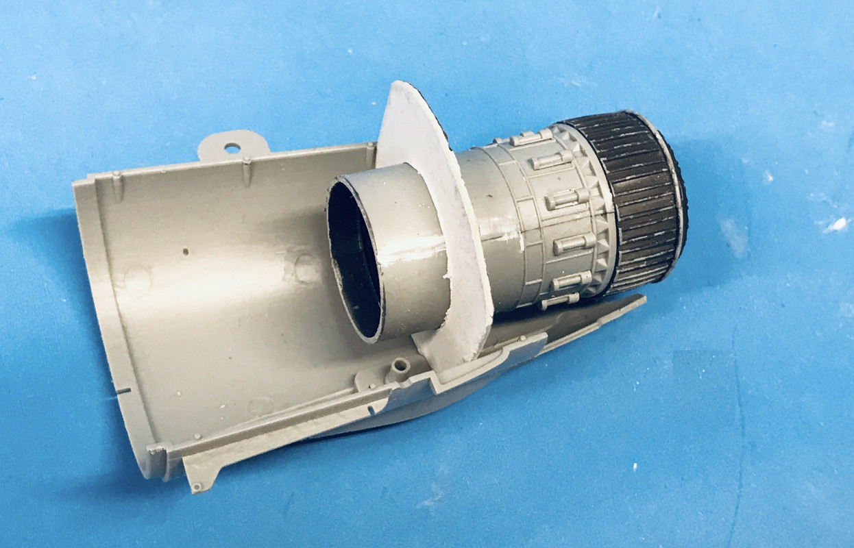
In discussion with Marty Schwambau at Scale Reproductions yesterday, he suggested that if I want to display the engine AND had the ass end of the plane complete, that I could cut off the afterburner section and put that into the plane. One of my pics the other day shows the engine just like that with the AB tailpipe removed up to the flame holder.

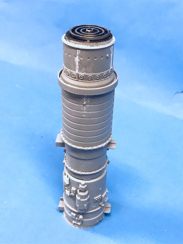
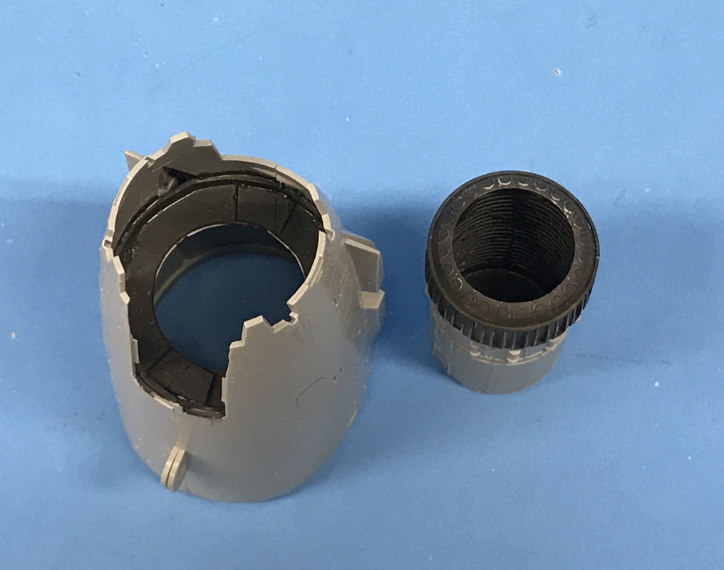
So I bit the bullet and sawed off the AB pipe with the micro-saw. It turns out that the simulated bolt circle, which I cut jut aft of, is the actual place where the flame holder is I I didn't screw that up.Needs som painting and TLC, but it's okay. To stand the engine vertically for this image, I made an adapter piece of some junk MDF with a hole in it to accommate the bulge at the compressor inlet so the engine would stand straight up without falling over.

Since the engine is centered in the fuselage with the four lugs projecting from the engine proper, the AB section had nothing to hold it in. So I had to make some bulkheads to center the engine in the tail section. This took a bit of crafting.

I started with some card stock, tracing the rear-most tail section of the tail cone held together with a rubber band. This was not the size that would be needed since the bulkhead was going to be positioned further into the tail cone where it was narrower, but it was a staring point to get the contours right.

I drew center lines in both directions where I cut a hole that matched the AB pipe's middle dimension. I cut that hole in the card and trimmed it so it fit the AB nicely.

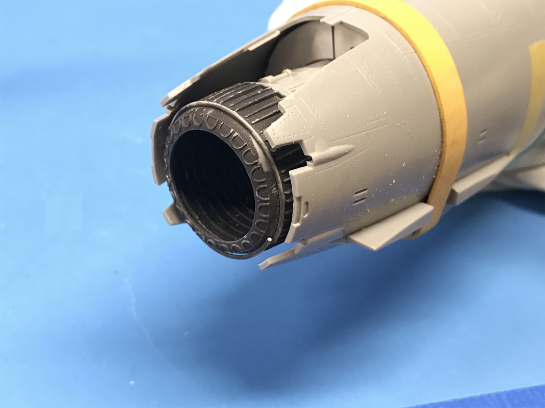
I cut the o.d. and then started trimming the diameter evenly just on one side until it fit decently into the spot that placed the exhaust's end just sticking out at the correct distance. I kept fitting unil it work and the center lines were still corresponding to the edge of the 1/2 tail cone piece.

When it was finally right, I transferred the profiles to some 0.040" styrene sheet. I only traced the 1/2 that was correct, and then traced it again to make the other half. This was I was assured that the engine was properly centered. I cut the styrene by scribing with a #11 blade and breaking on the line. I glued each bulkhead half to their respective sides and tried it out.

After gluing with solvent cement, I went back and hit it with thick CA to close any other gaps. I then followed up by glueing in 0.040" X .100" styrene strip so not gaps were visible. Lastly I closes some gaps at the juntion between the two halves with some more 0.040" styrene cut to the same contour as the bulkhead. 

I painted it all with burnt iron.

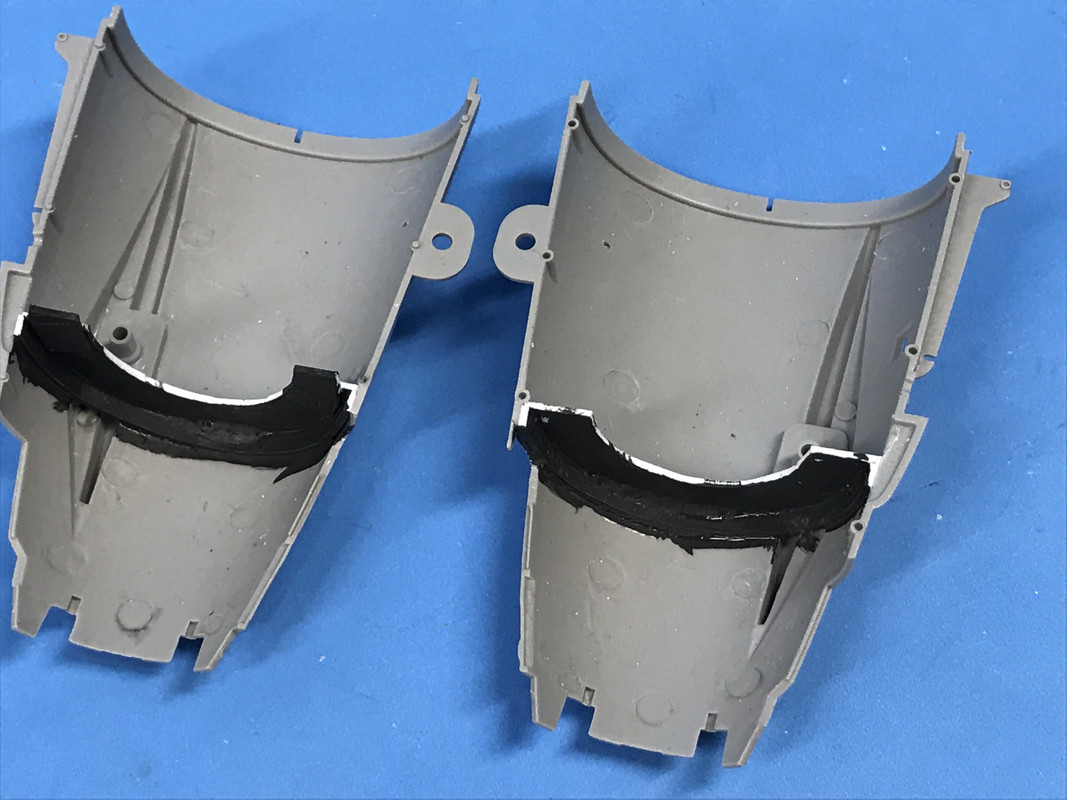
Here's the two halves fit together showing how the bulkhead appears from the outside.

With this important mod out of the way, I can relax about detailing the rest of the engine for the display. The more I think about it, I would be so much simpler desiging and building the work stand instead of the traveling one.

To make the installation even more secure. I wanted to put some side stabilizes between the bulkhead and the outlet of the tail cone. I was next to impossible to find that distance on the tapered portion. So I took some Sculpey Clay and put a ball of it on the cone where I wanted to get the dimension, and put the AB in place and centered, pushing it into the clay. I ran out of time to fire the Sculpey to harden it. I'll do that tomorrow. I'll finish shape pre-shaped Sculpey and will glue it to the wall and the AB. This will perfectly secure it. I do the same for the other side.

  • Member since
    March 2012
  • From: Louisville, KY
Posted by Builder 2010 on Tuesday, April 2, 2019 6:03 PM

Not much to report today, but I did solve the "Yellow Weather Striping aroud the Canopy" challenge. I bought 1/32" yellow striping tape and the LHS. That will work just fine. We also researched more about how to build a Jet Trailer, but didn't come to any conclusions. We estimated that the tires measure probably about 20", and the girders somewhere between 6" and 10". I could probably use aircraft wheels regardless of scale if they come out to 20" at 1:32.

Depending on how easy or hard it is to build the cart, I may rethink my plans regarding the jet engine installation.

  • Member since
    March 2012
  • From: Louisville, KY
Posted by Builder 2010 on Monday, April 1, 2019 6:52 PM

Just because someone else has AMS, doesn't mean that I have to succumb. That being said, I found a lot of nice pictures if I ever actually get the urge to go overboard on places that no one will ever see. 

I also got some pictures showing a vast range of different kinds of stands to hold jet engines. Out of them should be one that will work.

I put the main gear into their slots on the wings, added the actuating link and prepared it for soldering, by wire brushing the area to receive solder. Again tried to use the resistance unit on the first one, but didn't work so I used the torch. But I was able to use the resistance on the second gear by grabbing it in a slightly different way.

Since this brass piece was sitting in a styrene wing, I had to put heat sinks on both the main gear and the link to protect the plastic. For the gear I used a hemostate and for the link used a spring-loaded tweezer. It worked! The heat did not distort the plastic. By soldering it with the gear in position, I was assured that the angles were correct. I will epoxy the gear into the wing.

I soaked all three in vinegar for a few minutes to do a micro-acid etch to help with paint adhesion. Then I washed them in water to remove the vinegar and then in iso alcohol to remove any excess solder flux.

I rattle-can sprayed them with Tamiya gray primer. Did some touch up and then let them dry.

I then painted them with Tamiya Rattle-Can Bare Metal. It has a nice sheen. I will either paint the oleo slide with the Chrome Pen or wrap it with Bare Metal Foil. There's not much slide showing on the front gear.

Lastly, I started adding more piping gizmos on the engine to match the photo that I have. I drill the plastic with 0.032" carbide, then open it up bit with an 0.034" so the .8mm brass tubing would slide in more easily. It's very easy to crush this ultra fine tubing if the fit is too tight. I added all the exhasust petal actuators. In one picture it shows these burnt brown color, but it another it shows the actuators to be bright metal and everything else burnt.

I also filled those few annoying cracks with Tamiya filler. I predrilled some other places where pipes are going to attach to the engine. When I'm done it will be very busy looking. I'm using the .8mm Albion Brass which is a perfect fit of the .5mm solder I'm using for the tubing.

I found a lot of good detail pics, showing piping, especially tubing around the gear themselves. Here's a sampling. This Thud's been sitting for a while considering the rust on the oleo slide. That gear will never move again.

This pic clearly shows where the main gear actuator interacts with the gear. It connects to the side of the locking link, not the main gear strut itself. It also shows that the link folds towards the viewer in this picture. It was really helpful in having me figure out the relationship when I soldered those links to the main gear.

Here's a shot at the wiring that runs the Vulcan cannon. I will be doing some of this since I'm going to have that hatch open. I'm not opening the radome in front.

Here's a shot looking up into the nose wheelwell.

Here's some jet stands, two of which are holding the J75. One has the afterburner attached, the other it is removed, and you get a good view of the AB Flameholder. This cart is very simple to construct. I just have to find some suitable wheels. Any ideas?

The brackets extending from the engine's sides are duplicated on the model and hold it to the fuze sides.

THis is the picture showing the shiny exhaust petal actuators. This engine is pretty bare bones with very little piping on display, so it doesn't help me very much.

This is the TF-30, the engine that powered the Tomcat in the background. Again, not a very complicated build for the stand. This one does have some of that cool piping. To me, the only thing that makes jet engines interesting to look at is all that piping. Lots of different metal colors to try and replicate.

Going to the hobby shop tomorrow and will look to pick up some other metal shades to help create that "Jet Engine Look".

JOIN OUR COMMUNITY!

Our community is FREE to join. To participate you must either login or register for an account.

SEARCH FORUMS
FREE NEWSLETTER
By signing up you may also receive reader surveys and occasional special offers. We do not sell, rent or trade our email lists. View our Privacy Policy.