Dragon 1/35 Panther Ausf. D w/zimmerit #232 - * Build Log *
Hey guys, I've resurrected a project I started up two years ago. I did a review if this kit a while back which you can find here if you're interested.
Panther D w/zimmerit In-Box Review
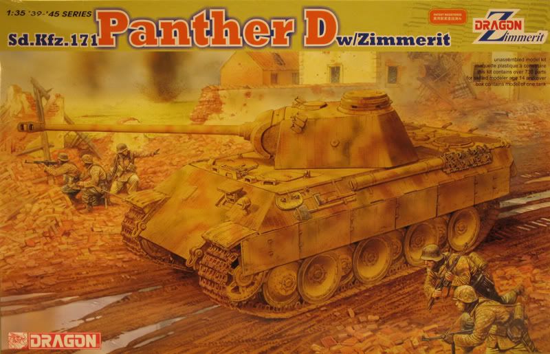
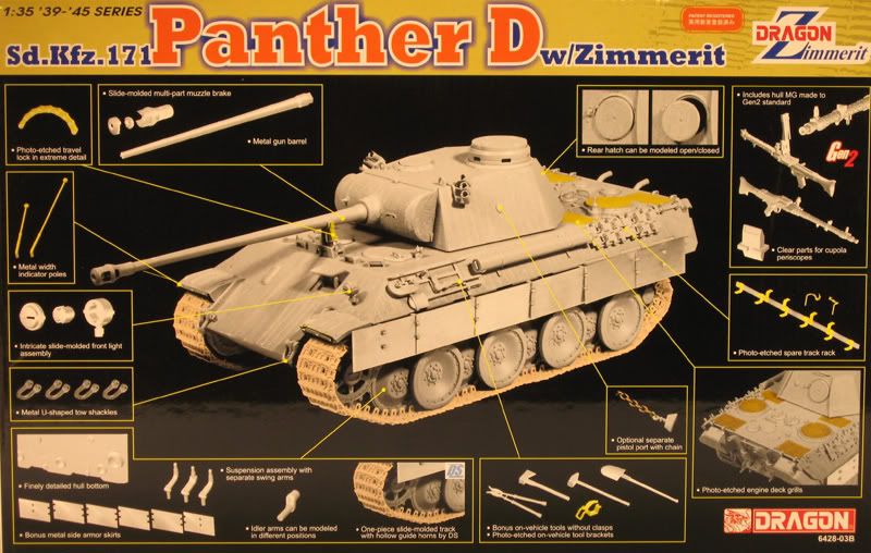

I found the markings in the kit a bit boring, so I picked up the excellent Echelon decal set ATX351009 which features markings for various Panther Ausf. D and a couple for the Ausf. A. Included are some gorgeous markings featuring red, black or white snarling Panther heads with Pz.Abt. 51 and Pz.Abt. 52 around the time of Operation Zitadelle. One of these days I'll do one of those schemes, although it will have to be on an early Ausf. D without zimmerit.
For this build, I have decided to go with:
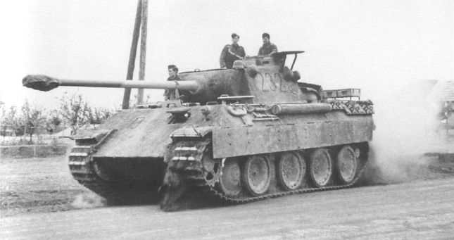
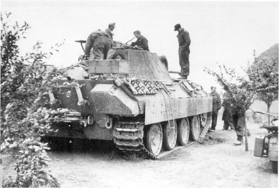
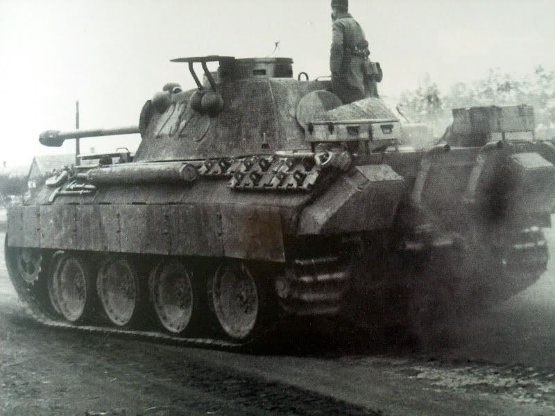
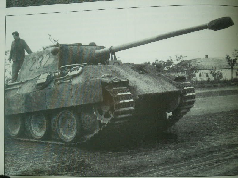
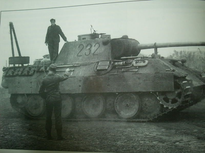
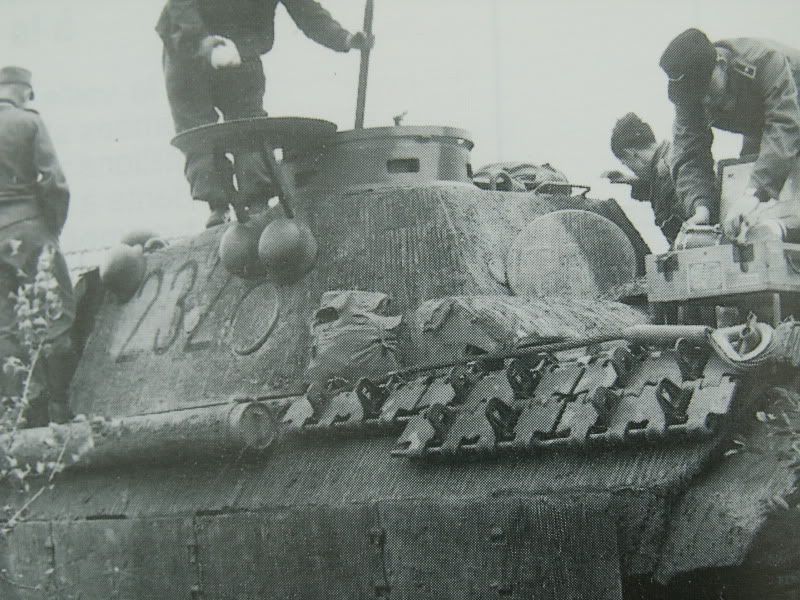
* Panther #232, 2nd Company, 15 Pz.Rgt., 11 Pz. Div.
I like the camo scheme and I have some good reference photos of this specific vehicle.



Construction begins with the running gear and lower hull.

The suspension arms have been attached, as well as the final drive housings and other runner gear components. So far it's been a very easy build with no fit problems, however the locating pin located on the back of the fatter end of the final drive housings needed to be removed because there is no corresponding locating hole for it on the hull.

For those that plan on building this kit, be aware that the suspension arms 2nd from the front and 2nd from the rear are supposed to have that raised seam on them running down the middle. Also note that those components are beefier than the rest of the suspension arms.
Once I got them all attached I lined them up by resting just the ends of the arms on the edge of my workbench while simultaneously putting a stiff straight ruler on the top half so they would line up correctly as they set. Because some of the arms are thicker than the others you can't use the tried and true method of just setting the kit flat on the table as the thicker ones will wind up with the axle slightly above and out of alignment with the rest of the arms. Make sense?
I will be using the "template method" to spray the road wheels. First they will be painted a mix of flat black with a touch of gray to simulate the slightly faded look that the rubber gets from exposure to sun and the elements. Using a drafting template with various sized circles on it I find the hole that best matches the size of the metal road wheel portion and use that as a mask to spray the base coat. I will document the process with photos when I get to the painting stage of the build. In the mean time, the wheels have been cleaned up and are ready for painting.


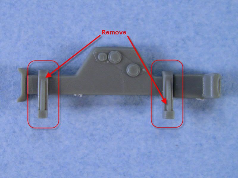
As you can see in steps 5 and 6, some modifications need to be made to the exhausts and the jack if you decide to go with the photo etch option included in the kit.

First up are the exhausts. The grooves in the pipes needed to be filled and the excess plastic on the back needed to be removed. The modifications are necessary to remove anything relating to the plastic brackets in order to use the the photo etch brackets provided in the kit and to get them to fit properly. I carefully trimmed off the plastic on the backs, then filled the groove with squadron white putty.
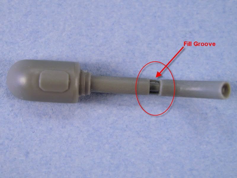

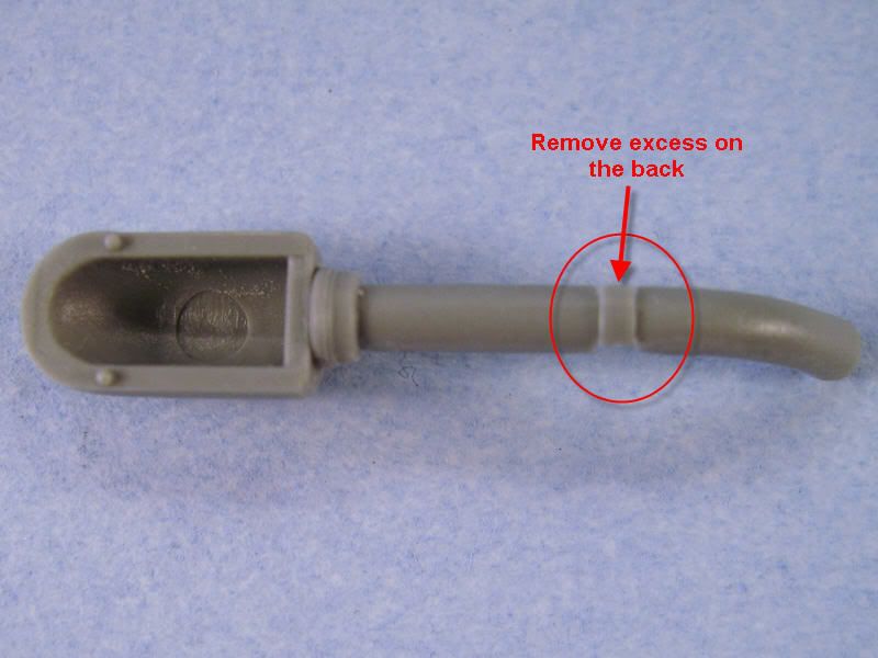
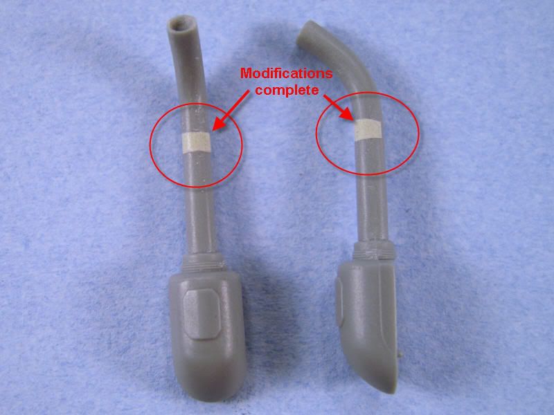
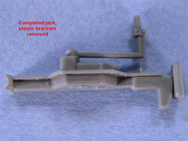
Then came the jack modifications. I carefully cut away the plastic brackets using a #11 blade, then carefully sanded everything smooth.


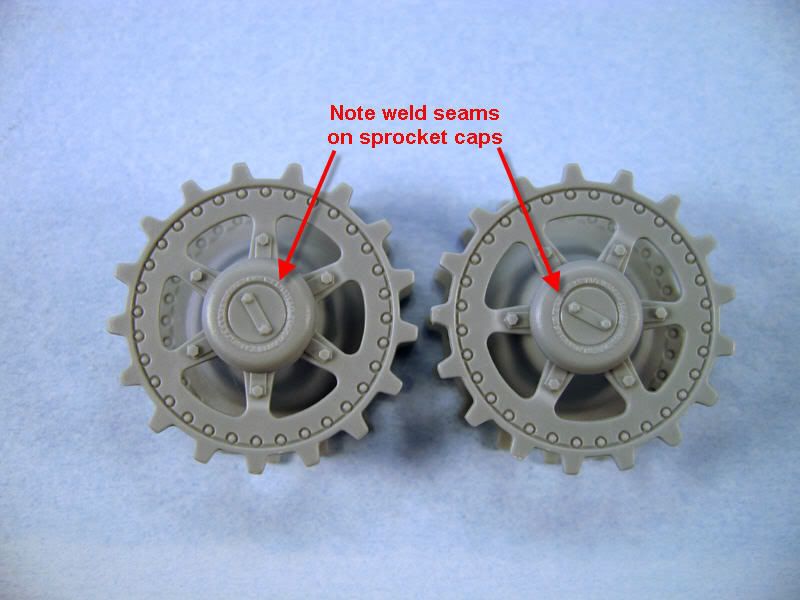
The drive sprockets look great, as do the idlers. There are two different sprocket caps included in the kit. The more recessed cap appears on earlier variants of the Panther Ausf. D. Be sure to check your references carefully to be sure you're using the correct cap for the vehicle you're modeling. The vehicle I'm modeling features the later sprocket cap with the weld seam going around it.

After I got the jack brackets assembled I did some test fitting etc. I think what I'm going to do is shorten the part of the bracket that attaches to the plastic attachment point so that I can glue it behind the tab. There is a pocket of space there so if I glue it to the back of the tab, the rest of the bracket will fold forward and for all intents and purposes the PE parts will be roughly flush with the plastic part. That should put everything in the right place and the jack will prevent you from seeing that little "shortcut". Make sense?