SEARCH FINESCALE.COM

Enter keywords or a search phrase below:

Rye Fields Sherman M4A3 76W HVSS with Full Interior: Start-to-Finish Build

23547 views
107 replies
1 rating 2 rating 3 rating 4 rating 5 rating
  • Member since
    March 2012
  • From: Louisville, KY
Rye Fields Sherman M4A3 76W HVSS with Full Interior: Start-to-Finish Build
Posted by Builder 2010 on Saturday, July 18, 2020 12:15 PM

I just finished another structure project for my model railroad: a backwoods cottage industry making railroad ties, that also features "Johnny B. Goode" "Carry his guitar in a gunny sack, and sit beneath the trees by the railroad track. The engineer would see him in the shade, strumming to the rhythm that the drivers made." I had envisioned JBGoode sitting there when this kit "the Tie Hacker's Cabin" first came on the market several years ago. I had to have it custom made by Shapeways. They had a guitar figure standing which I asked the artist to put in a cross-legged position. 

My approach is to build something for the trains and then do something in plastic. My last plastic was the Airfix Typhoon 1:24 Car Door Version that I documented in the FSM Aircraft Forum. My next project is this. I picked it up this week at Scale Reproductions Inc. It's the recently released Rye Fields Sherman M4A3 76W HVSS with Full Interior. I missed getting the Abrams with Interior by the same manufacturer. I didn't want to miss this one.

The kit is awesome in the fullest sense of the word. It has some PE, but there's an aftermarket set with brass fenders that I chose not to get. I may reconsider. The kit lits over 1,900 parts, 900 of which are the multi-part tracks that are fully workable. That leaves another 1,000 just for a tank kit! I have a special place in my heart for the Sherman. It was the first military model I ever bought probably somewhere around 1955. I think it was Revell's first Army model. The other is "Long Tom". You never forget your first!

I often buy my kits on parts count and how thick is the instruction manual... I know... dumb. Anyway, of the kit's 62 pages almost 75% are just to build the amazing interior. This is the same Sherman featured in Fury, and I happen to own that movie as on Apple TV so I started re-watching it yesterday to glean more prototype info. Even though you won't see much (unless I rig it so the parts are displayed exploded), I'll know it's there and had the enjoyment and learning that goes along in building it.

In discussions I've read about Shermans versus Axis armor, it seems to be judged as follows: 

It was a good balance between hitting power, mobility, protection and crew comfort. It excelled only in crew comfort with it's high stature leaving lots of interior room for humans and ammo. The stature also gave the crew more visibility of the battle space, but also made them a bigger target. Most of ammo was below the deck, and in ths 76W model, stored in ethylene-glycol to prevent flash off in case of fire. It worked until crews starting adding more ammo scattered around in unprotected spaces. And, the Sherman was the only tank at that time of the war that had a gyro-stabilized main gun. It enabled them to shoot on the run and gave them a strategy where they could pre-align the gun, rise up out the revetment and fire before the enemy had a chance to react. It was a game changer. I didn't realize the Sherman had this capability until seeing a video about it. The gun was so well counter-balanced that it could be raised or lowered with a finger when the elevation gearing was disengaged.

Of course the Tigers were bigger and packed a bigger gun, but there weren't very many of them, it was late in the war and Germany was logistally challenged, while we were building more and more of them. What we didn't deliver in fighting power, we delivered in sheer numbers. US tactics always had Shermans going off in groups of five. Even if there was a Tiger, it was a 5:1 proposition.

We continuously learned during the war and kept upgrading the tank in every category until the next interation of lower-profile tanks was born with torsion bar suspension. Of course the Germans already had torsion bars. The engines evolved from a Continental radial to the massive V8 G44 Ford gasoline beast that produced over 500hp and over 1,000 ft pounds of torque. The engine was a true dual-overhead cam, four-vlave-per-cylinder affair that was modern even measured against today's standards. Cams were all gear driven which imparted robustness to the design. There were diesel verisons also. The engine was never taxed to its limit in Sherman service. This model represents a late model Sherman that saw action in 1945.

I viewed some video reviews of this Rye Fields model WITHOUT the interior and it was an early kit that showed some very noticeable mold seam lines. Although I have't debagged any parts yet, I noticed no seam lines. The kit is molded in gray plastic and it almost flawless from what I can tell looking through the celophane. It can be decorated in three versions. I haven't decided on which yet. It also has a choice of three drive sprokets configurations. Again, I haven't picked and since the kit gives no guidance on this, have absolutely no idea on what to base my choice. Some help from the audience will be helpful. I'll post images of the three and you folks can tell what is what.

Construction will begin in a couple of days. Enjoy the ride!

  • Member since
    March 2012
  • From: Louisville, KY
Posted by Builder 2010 on Thursday, July 23, 2020 9:01 PM

Work officially commenced today on the Sherman. I started by unpacking all the sprues and installing them in my home made cardboard engineered sprue holder... which, BTW, I received a small fee from FSM by having this idea noted in the Tips & Tricks column a couple of months ago. Thanks FSM. The holder only goes up to letter "R". I didn't realize how many models I would be building with more alphabet sprues than R, but they do. I like building big, complex kits. The kit had a "V" and "W" Sprue, but missed a lot of the rest of the alphabet so I renamed two of the non-used letters as V and W. The holder is held together mostly with hot glue and some strategically placed duct tape.

The kit's molding is exceptional (Tamiya level). Some of the parts are maddeningly small. The Xacto serves as a size comparator. You hae to be very, very careful in removing from sprues or you will eat the part in the process. Just look at part #9 on the top of the image. It looks like a some kind of lever, although I don't know exactly what it is. With parts that fine too much solvent cement will dissolve the entire part.

The mold texture is also terrific. Here's a closeup of the forward top surface of the hull showing the casting texture and the cast in part numbers found in the real tank's casting. Weld seams are beautiful and don't have to be scratch-built by me and much appreciated.

Construction starts with drilling a couple of holes (.8mm) in the glacis plate in the body front. You only drill the outer two holes (the others are probably for a different version). .8mm is the same as a a 1/32 (0.032"). After drilling you glue in a backing plate that is the interior version of that same plate. It has bolt detail facing inwards. I used tube cement for this since solvent cement is not very effective on large pieces since it evaporates too quickly to develop a solid bond.

There are five pieces of small PE in these early steps. Two represent sheet metal levers that operate the hatch release counterbalance. The others look like internal hatch locks, and the last is a sheet metal platform on the highly complex ventilator assembly. Notice the full periscope transparent parts are also in place at this stage. Everything inside gets painted white. I was toying with painting backing glacis plate off the model, but decided I'll paint it with the rest and mask whatever's necessary.

Most normal models would have this be one or maybe two parts. Here are the ventilator parts. One is being folded in my Small Shop small Hold-n-Fold.

Here's the ceiling with the venilator attached. Even though the instructions show the little PE platform being glued to the blower housing before installing on the ceiling, that was functionally impossible. You can't glue PE edge on with the other two edges hanging out in space. And there are two boxes that go onto the PE AFTER it's glued in place. So I glued the blower on first and then attached the PE and the boxes. I used Gel CA to glue on PE. You can apply a tiny amount. It stays where you put it... doens't run or ooze. And it stays uncured long enough to manipulate the part into final position. This is a recent change in technique on my part. Brian Bunger, the owner of Scale Reproductions, Inc. (our fantastic local hobby shop here in Louisville) told me about it. Prior to this I used to try to use thin CA with lots and lots of headaches.

Considering how much detail just went into the overhead of the driver and second drivers station, this model is going to be awesome!

Stay tuned, this is going to be fun!

  • Member since
    September 2013
  • From: San Antonio, Texas
Posted by Marcus McBean on Friday, July 24, 2020 2:42 PM

Off to a fine start.  This will be quite a paint project.

Marcus Beer

  • Member since
    March 2012
  • From: Louisville, KY
Posted by Builder 2010 on Friday, July 24, 2020 6:10 PM

Before getting started today I further enhanced my sprue rack by duct taping it down to the work surface to reduce the chances of knocking it onto the floor and doing some damage.

The day started by assembling the front portions of the mud guards. These are two-part affairs with a beveled edge that is glued flush. There were no alignment aids and I just had to hold one end in correct position and secured it with very small drop of Tamiya Super-thin Fast Set liquid adhesive. When that end fused a bit I aligned the other end, did the same and then applied cement to the seam length.

The long guards had too tiny alignment lugs at their extremis. It had a very small ledge which rested on the hull. I did the same for this as the fender front. Started at the back and when I got it with the ledge and lug at the right spot, put a touch of glue on it. I gave it a few seconds to start setting and then slowly moved down the length "spot welding" the glue until I reached the other end. I then went back and applied standard tamiya solvent cement to the entire length.

Top View:

From the bottom. Note: the long fender does not contact the front. I wish it did since it would strengthen both parts. I even thought of applying thick CA to the joint from below, but didn't.

Next up was some finicky work on the drivers and asst driver's hatches. During this exercise I lost 3 parts. Two I scratch-built and one I just left off since it's on the upper side of the 30 cal machine gun and that side is up against the ceiling. The hatches have a persicope assembly, two hand grabs (top and bottom) and a little piece of nothing that does something on the real thing, but serves only as a gribbly on the model.

One of the gribblies got lost AFTER I already got it in place, but wanted to remove a tiny little divot left over from the sprue. It was then that I lost it. Sometimes it's best to leave well-enough alone.

The above also shows another scratch-built piece. One of the hand grabs went bye bye from the tweezers. Tweezers are the bane of my existence. I imagine many others too. I bent one from a piece of 0.010" wire after drilling some holes to accept it with a carbide drill of the same size. Those drills are ridiculous. I have no idea how they're made. It defies explanation. To grind tungsten carbide you can only use either silcone carbide or diamond. I have one of these drills permanently inplace in my left thumb. I went to put it back in its holder box and it stuck me and broke off inside my thumb. Tungsten carbide is essentially innert being soluble in hydroflouric acid. If anyone has watched "Breaking Bad" you know exactly what Hydrofloric acid can do. My doctor son in law says if it doesn't bother me don't worry about. It doesn't bother me.

Frankly, real metal grabs work better. I'm not worried if I lose more, I'll just make them.

The periscopes are a nice touch. The brush guard on top has two choices: styrene or PE. After looking at some closeups of real Sherman periscope guards and found that they were not from flat sheet stock. They were round rod and actually look like castings. The brush guards on the headlights, in contrast, are welded out of flat stock. In those I will use the PE.

The transparent parts need careful painting to keep the bottom and top lenses clear, but the rest should be olive drab. I will create some very tiny pieces of masking tap to accomplish this. I thought about liquid mask, but that's not always as easy as it seems.

The Browning 30 cal had another tiny part that departed this dimension. It too will never be noticed, not even by me. The engineering on this gun was dubious and there was no way to make it movable without it becoming "removable". I glued it all in place. I didn't lose the hand grabs for the hatch tops. The fixed periscopes will get an armored cover.

I don't "work" in the shop on weekends. Everyone have a nice one.

  • Member since
    March 2012
  • From: Louisville, KY
Posted by Builder 2010 on Wednesday, July 29, 2020 9:58 AM

It's been a frustrating couple of days. First of all I prepared the headlights to receive their lenses by coating the reflector with the Molotow Chrome Pen. It gives a brilliant, smooth and un-paintlike metallic surface. I will ptu the transparent parts on with Testor's Canopy Cement.

I then got to attempting to build the multi-part brush guard that protects the siren on the left front position. The two guards over the headlights are single piece PE, but this one is three parts that are supposed to be CA'd together. I choose to solder PE whenever possible and have a resistence soldering unit that makes tiny soldering jobs possible. The problem here was two-fold. They etched the band to provide a resting place for the horizontal inner bar. One of the legs broke at this etched groove that really complicated the job.

This is the instruction for this guard. As you can see, it would be touch and go to use CA since the bent brass loop would be providing a lot of tension against the glue joint and any undo pressure would immediately distort the part. it's really tiny.

Here is the next step which shows the installation of the guards. What makes matters worse is the butt joint that holds the brass to the styrene hull. Very tiny surface area which any glue (including CA) is loathe to like. I guarantee that it will break off at least once during construction. In fact, it should be left off until the very, very end. At lease if I make it out of styrene, the glue will weld the parts to the hull. You only have PE for this part, not injection molded alternative.

This image shows the PE cross piece soldered. It's not exactly right. The pieces should be nested closer in the etched cross-lap joint. But I could have worked with it. Behind it you can see a bit of the main loop and also you can see the etched groove I note above.

When the loop broke at that etched joint, I soldered it back on. While this held for a while, every time I attempted to solder the inner cross, the joint would separate. I tried using solders of different melting points, but the metal is so thin and narrow that the heat too quickly melted neighboring joints. Then the inner cross fell apart the shorter of the two pieces also broke in two. 

I then cobbled together another cross using PE fret material. I have tons of this stuff left over from other models and it comes in very handy as a source for thin brass stock. This worked.

The above was my fourth and most successful attempt. The darn pieces kept hitting the floor and disappearing into the dimensional rift. Of all the pieces I've dropped of this model (so far), about 1/3 went inter-dimensional. While the cross bars were successful, the loop got worse and worse. It became unusable. I was licked!

I wrote to Ryefield Model USA to request more PE, and am now in process of making my own plans for this silly little detail and going to attempt to make it out of styrene. It can be done, but it will be very, very delicate. Wish me luck. 

I hate it when the smallest details eat up the majority of bench time. It's Parkinson's Law, or a corollary of it. Parkinson found that the smaller the amount of money being considered, the longer the time spent on the decision. Other Parkinson observations include: Junk expands to the space allowed; Work expands to the time allowed; and his main thesis, Adding an assistant doesn't halve the work. It only reduces it by a third since you have to now spend time managing that person which takes you off task. To halve the work you must add two assistants.

The first step in scratch-building a new one is making a full-scale plan of the part. I took a picture of the PE sheet, will import into CorelDraw and then draw a full-scale copy with can be stuck to some styrene to cut out the replacement. The image is greatly enlarged. The full width of the PE sheet is 3.07" across. I will use that dimension when importing the image into CorelDraw. That will ensure me that all the parts in the frame are correctly sized. All I have to do is trace the image and then created a line drawing that I print out and use as a pattern.

I also took some PE and CA'd it under the junction between the front and side mud guards. The joint was proving very fragile due to the thin cross-section of the front mud guards that was potentially going to break at that point.

  • Member since
    March 2012
  • From: Louisville, KY
Posted by Builder 2010 on Wednesday, July 29, 2020 6:56 PM

Perhaps while I write this build thread I can do a kit review at the same time. I'm forming an opinion about Ryefield Models. Unlike Tamiya that seems to nail both wonderful realism AND good engineering helping to make a successful build, Ryefield does a great job on realism, but it can be at the expense of buildability (if that's a word?). In an attempt to try and re-create a 1:1 faithfulness of details, you're expected to join parts with almost no gluing surface area. While styrene is a great modeling medium, it lacks inherent strength and will be very fragile is low-surface-area joints. Also, the application of PE in locations where the odds of future breakage is 100% is not an effective strategy. As I go through today's progress I'll point out these areas in more detail.

Now... granted... I may simply be not a very good builder and a little klutzy, but I don't think so. I've built some pretty remarkable models and if I have trouble, lots of other people are going to have trouble also.

I finished up the front end of the upper hull by assembling the headlights, the horn and the other little bits including gas filler caps (which, BTW, completely cover over a detail that was inserted from the bottom yesterday. I'm now wising up. I'm leaving off any detail that will be wrecked in further assembly until the very end. A perfect example of this is the rear veiw mirrors. They are actually held to the hull with a tiny folded PE bracket that captures the mirror shaft. This will certainluy be fragile and fail the moment it is touched. I'm also leaving off those PE brush guards. I also cut very tiny strips of Tamiya masking tape and masked the lens area of the periscopes. They will be a delicate, but definitely cool paint job that will add some definite interest to the most critical model viewers.

The headlights themselves are held by tiny pins and were constantly wanting to either come off or bend over. I reinforced them with CA in hopes that they'd stay put for the rest of the build. The pin size is arbitrary and could have be double the thickness and still been invisible after assembly. The whole deal is providing adequate gluing surface.

I added the details to the rear hull deck too. Funny... they didn't give you a styrene option for the front brush guards, which I would have really liked, but did provide them for the tail light guards. Go Figure... I used these. They look pretty good and welded to the surface nicely.

The gas caps should go on AFTER the rear deck grills. Reason? There's a pull pin that's molded on the gas cap that extends into the grill area. It is way to easy to break it off. By following the instructions, which I did, you have to carefully slide the assembled engine deck grill forward under this little details or you will destroy it.

Another area of concernis the rear lifting lugs. No Pins at all! It's a butt joint with very small surface area. It's unnecessary to make this part without pins. It complicates installation and results in a weak joint. I had to re-glue the left side. This image shows the styrene rear brush guards.

The luggage rack caused significant frustration. All of the joints were tiny and very difficult. They have you gluing the two parts onto the hinges themselves, which produced very little surface area... almost non-existent. The result was gluing and re-gluing until I scraped gluing it as they instructred and filed off the hinge details and turned it into a long butt joint... much stronger.

What made it even harder was the ejection pin marks on the back of these tiny hinges that had to be removed to get the fit correctly. I had to hold the hinge down with a tweezers while removing the divot with a new, sharp #11 at the very tip. Parts are pretty tiny.

The second frustration was four tiny folded PE attachment angles and 2-part PE shelf supports. I lost the set for one side, and basically destroyed the set for the other. The PE brackets got re-bent and when straightened broke off on one side. I ended up using single pieces of PE fret brass cut to the correct length and glued with Gel CA. All in all a lot of frustration. Tamiya would have approached it differently.

One thing that could have been a pain was installing 11 (on each side) angle fender supports. However, I'm happy to report, that other than shaing off the tiny sprue divots to assure a good fit, I took my time and all 11 went on without a hitch. You can see that these parts are quite small.

The end result of all these peices looks good and really looks like sheet metal brackets.

I finished up the day gluing the rear panel with the luggage rack onto the rear hull and giving it all night to dry properly. Those joints also were almost entirely butt joints with take more care to keep them aligned while gluing.

I'm sure this will come out as a spectacular model, but it will definitely be a "Look but don't touch" kit. If you touch it, pieces will definitely fall off.

  • Member since
    November 2009
  • From: SW Virginia
Posted by Gamera on Thursday, July 30, 2020 11:42 AM

Wow! I've looked at that kit but I need another M4 like I need another hole in the head. 

But love what you're doing here! Great job!!!


BTW: I hate those gadawful headlight guards too!

"I dream in fire but work in clay." -Arthur Machen


  • Member since
    March 2012
  • From: Louisville, KY
Posted by Builder 2010 on Thursday, July 30, 2020 5:02 PM

I am not patient, but I am persistent. I'm on the fourth iteration of this #(%90 guard. I was able to draw the part in CorelDraw over top of the scaled image of the photo-etched diagram in the instructions. I made many copies of it, since they're tiny and I'm printing an entire letter-sized page, so why not. And... I generally screw a couple up. (which I did). My first attempt I cut on the lines, but it came out too frail to be workable so I cut the next one outside some of the lines to give it more heft.

My first attempts at cutting the cross-bar parts were also too frail, but then I got it right and was able to glue together a very small cross-lap joint which I let dry in prep to install it into the hoop.

Early on I realized that gluing the entire hoop to the hull at one time, or worst, gluing in the cross-bar before putting it on the tank, would be very difficult. I chose to glue one set of legs to the hull and after it dries overnight bend it over to glue the other side. My first go was a big "DOH!" I glued it to the wrong place over the headlight instead of the horn. The headlight hoops (still PE) don't have that darn cross-bar. I had to pull it off and destroyed it in the process, so I cut another out and got it sit down well.

After this part set up a bit, I glued on the cross-bar to the hull and to the already-glued side. When this if fully set up I'll attempt to bend it over and glue the other side. And then I'll pray that I don't knock it when handling the tank and wreck it. Meanwhile I havn't heard from RyeField's about my request for more PE.

While this was setting up, I started working on the working hull. These parts have both sides exposed and there were ejection pin marks. I use the MicroMark chisel that is especially good for this kind of job. It's heavy, has a flat side and can be honed to a very sharp edge. You apply smooth pressure and take your time, being careful not pushing so far that you'll knock off details on the other side of the cut.

This is another part that has very little guidance to make a very long and critical glue joint. There is one alignment lug on one end. The rest of the joint is an unguided butt joint. You start at one edge with some tack gluing and then the other end carefully aligned. Finally you go back and apply cement to the rest of the joint.

I set up the joint with a square block to keep it in alignment while setting.

While this side was curing I did the same to the opposite side. After this the return rollers started going on. I'll show this stuff tomorrow. Today was my 75th birthday and we're heading to my daughter's house for food and cake (proper social distancing, of course). And I don't feel a day over 74. I also did a half hour each on the elliptical and recumbent bike so I'm trying to keep all my gears going.

  • Member since
    July 2004
  • From: Sonora Desert
Posted by stikpusher on Friday, July 31, 2020 12:04 AM

Well this certainly is quite the exceptionally detailed model. Are you going to leave the upper hull free from the lower hull to show off all of this interior detail?


F is for FIRE, That burns down the whole town!

U is for URANIUM... BOMBS!

N is for NO SURVIVORS...

       - Plankton

LSM


  • Member since
    November 2009
  • From: SW Virginia
Posted by Gamera on Friday, July 31, 2020 8:23 AM

Happy birthday!!! I hope I'll reach 75, though I've got such a stash I'll take me to 575 to get all this built. 

I've glued most of my light and periscope guards in place with Gator Grip glue. It has a sticky nature that holds the part in place while it's drying. Plus it dries flexible so if you do poke the part when dry it tends to give a little instead of flying off to parts unknown like super glue. 

"I dream in fire but work in clay." -Arthur Machen


  • Member since
    March 2012
  • From: Louisville, KY
Posted by Builder 2010 on Friday, July 31, 2020 5:43 PM

I am going to figure a way to have all the main parts exploded into space so all the interior is viewable. It would be criminal to hide 600 (or more) parts from view. I glued the periscope with the solvent cement being very careful to just apply it to the sides. It worked.

My fourth attempt at making the horn's brush guard I will consider successful. I glued the one side yesterday along with the center cross piece. Today I attempt to fold it over to glue the other set of legs in place AND glue the cross piece to the new side. The hoop fractured at the leg joint, most likely due to microscopic stresses imposed by cutting with the Xacto. I removed the hoop section completely and left the new side to dry for several hours also.

I then fashioned a new hoop section with some 0.010" sytrene cut into a narrow strip. I glued on one side and again, let this fully cure before attempting to bend it over.

When dry, I folded it over, held the new end to the rest of the assembly with a tweezers until it set up enough to hold, and then glued the cross-piece into place on it. The results are a completed brush guard that, even though it's a bit rough could easily be passed off as a field repair that was done after the OEM was damaged by and errant tree branch.

It proves that it can be done. It's not as fine as the original PE, but since that no longer exists, it's better than nothing.

I finished gluing the return rollers on the two sponsons and then added interior details to them. The return rollers are fragile. The actual gluing surface is small considering the load they could be expected to carry (on the model) with the heavy track laid on it.

On this image, I've called out the number of pieces of which each of these details is comprised. Again, most models that I've built wouldn't make some of these details multi-part. But it does add to the ultimate fidelity. On the twin bottles, the bottles themselves was one piece, each of the gauge regulators was separate and then that very fine interconnecting pipe. Notice the canteen stuck to the sidewall in the bottom sponson.

I'm very happy that the brush guard challenge is now behind me. The good thing about scratch-built parts is that you can do them over and over until you get them right. It's Friday (again) so y'all have a nice, safe weekend. See ya on Monday.

  • Member since
    February 2011
Posted by GreySnake on Monday, August 3, 2020 5:47 PM
Nice job on the replacement brush guard. I admire the perseverance you have. It seems like Rye Field models have a reputation as be very detailed but also over engineered. I eagerly await the next update.
  • Member since
    March 2012
  • From: Louisville, KY
Posted by Builder 2010 on Monday, August 3, 2020 6:05 PM

Happy Monday!

Thanks for the kudos! As this build progresses, you'll be able to draw some pretty well-founded conclusions re: Ryefield. Case in point is the PE on the pintel. It's a difference without a distinction. PE parts where you have to captivate tiny pins of a third part are exercises in futility, at least with the tweezers that I use. And these are expensive Swiss fine point tools.

Remember when I said that the return rollers are very weak joints? Well... they're so weak that when I stopped down the basement to collect cardboard recycleables and took a look at the model (couldn't help myself), a return roller had already broken in half and I had to search for it. I decided that I wasn't going to trust the model to not break them when messing with loading the tracks, so I reinforced all four of them with 0.022" phos-bronze wire.

I spot drilled the center of the hub with a tiny 0.011" carbide drill and then followed up with the 0.022" carbide drill. I drilled deep enough to ensure that I penetrated all the way through the back roller. I then CA's the rod with medium CA.

I clipped the rod as close as I could with the flush cutters and then went back and carefully ground off the remaining stub with the Dremel Flexi-shaft with a round diamond-coated burr. I used a low speed and was very careful to not grind the plastic and not melt it either.

These rollers are now secure for the long haul. It wasn't an easy fix, but I would reccommend it for anyone building this kit. You may want to drill and reinforce before gluing the rollers to their mounts on the model.

Next up was bottom. It fits into three notches on each side and is a flush joint almost the full length of the sponsons. I worked to keep them square, but then when installing the back bulkheads it got more squared up.

After gluing in the bottom I glued in the back bulkheads. There are two parts; a horizontal member and the angled larger member. They are all long butt joints that I apply glue to after positioning the parts. The glue penetrates the joints by caplillary action and doesn't mar the surface too much. It will all be hidden by layers of paint. There's one little spot that will need some filler on the side opposite to the camera.

On the inside of the engine rear bulkhead there is a PE detail that will be completely (or almost completely hidden) by the radiator assembly. It's a two-fold affair. I bent it and installed it... crazy? Yes!

On the back bulkheads goes several pieces of detail. The pintel assembly consists of the bracket, pintel and three pieces of PE. The PE is ridiculously small and I did eventually lose one of the tiny brackets after fussing around with it too long. The idler wheel adjustment hubs are two piece affairs too. And there's the very interesting armored exhaust headers which was a late mod for the M4A3 series of Sherman's. Lastly there were two, three-part towing hooks. The hook snapped around the thicker one and intersected with the thinner one... yes... there were differences in these pieces that you needed to pay attention to.

Here is the hook in the snapped part.

And here's the entire rear bulkhead with all its details. Those exhaust headers look very well protected. You can't really see it, but there was a supposed to be another tiny PE bracket below that angular part on the pintel, but it disappeared after I tried to scrape off some excess cured CA.

Instructions now started the engine compartment details themselves. What looks like fuel tanks and side bulkheads plus some interesting little piping details. After doing trial fitting on the left side I found that it was best to install the vertical side bulkhead and then install the fuel tank.

There are alignment pins that help get the correct parts into the correct positions. Notice the engine mounts are going it at this stage.

The right side duplicated the left details. In this instance, the tiny pipe running the sponson wall to the tank popped out of my hands. I found it a good five feet away from the work area. I was able to see the direction in which it flew away which gave me a strating point, but I was still surprised that it flew that far.

To give another idea of the detail level of this Ryefield kit, here's the lever that would open the escape hatch on the hull bottom. This was a separate part. It's the hatch that Norman used to escape the tank in "Fury" and save his own life in the eponymous movie.

Now I'm facing a potential dilemma. I've been leaving all painting until the major assembly is done, but as I look at the details being added in the hull, I'm starting to doubt my decision. Hand painting the details AFTER assembly would block painting the backsides of most of those parts. But, on the other hand, if I prepainted all of them, they would all have to be scraped to remove paint before gluing. I think I'm going to paint the white before the drivers controls go in because they are all grey colored and not white.

  • Member since
    February 2011
Posted by GreySnake on Tuesday, August 4, 2020 10:51 AM
Nice fix with the return rollers. My Miniart T-54 with interior is looking a little less intimidating to build after see what you are working with. Keep up the good work.
  • Member since
    March 2012
  • From: Louisville, KY
Posted by Builder 2010 on Wednesday, August 5, 2020 10:32 AM

Thanks! I just wrote and entire paragraph about not being afraid to use small drills and metal rods to reinforce dubious mechanical glue joints, and for some reason hit delete instead of enter and lost the whole deal. Needless to say, I was talking about using tiny carbide drills for this. I buy them in sets of 10 from Drill Bits Unlimited. They're solid carbide with 1/8" shanks and are very sharp and useful, but brittle as glass. For the tiny 0.010" drill, if you put any side thrust at all you will break it. If you lay it down on the bench and accidentally touch the tip, you will break it. If you place a tool next to it and accidentally touch the tip, you will break it. In other words, regardless what you do, you'll break it. I'm lucky if I get 3 holes per drill, but for making holes for guitar High-E string music wire it's the only way to go. And that sized wire is very useful for whip antennas, and guy wires for 1:350 ship masts. It's also a good size to reinforce small diameter shafts.

Now onto the Sherman:

I did a lot of work on the driver's compartment and will descibe it as I go along. First was the clutch lay shaft. It had a tiny piece of PE on it. I glued the shaft in turned 180° and it put the PE in the wrong place. I broke it off, re-glued the shaft properly and then added back the PE. I find the hardest thing about gluing tiny PE is keeping it from sticking to the application tool instead of the workpiece. A tiny bit of CA on the tool and the part chooses it versus where it's supposed to go. Murphy at work!

The clutch pedal, a fragile affair, broke apparantly when detaching it from the sprue. I didn't know this until assembly when I saw it didn't match the drawing (which are very accurate) and was missing the part that connected to the lay shaft. I glued in the front part. All of the pedals and levers are trapped between two brackets each that glue to the deck. I found after messing around, that gluing the brackets to deck first and then spreading them a bit and inserting the pedal worked better than gluing the brackets to the pedal and trying to get it all attached to the deck, even though the instructions showed doing the latter.

After dropping some other tiny part on the floor and sweeping the area, lo and behold, the missing clutch pedal piece showed up. As I said, I wasn't even aware it had fallen. As Mark Knopfler sang, "You might get lucky sometimes." I am not being very careful in how I apply the liquid cement to all this stuff on the deck. It's going to be covered with paint and some weathering. Notice too the little clutch spring on the lower end of the picture.

The steering brake levers show to not GLUE then to their brackets. That's because you'll need to align their ends to the braking shafts that go in later and you don't know the angle that's going to be needed. Again, I glued the two levers together and let them dry.

These brackets also were glued to the deck and then the levers put between them. They are movable.

A couple more pieces went down and then a cover plate was glued in that hides most of these nice levers and bars.

Kinda makes you wonder why all the detail is there, doesn't it. That's kind of like the entire model. BTW: the mold quality is terrific. There is rarely any flash that needs removing. I'm really only removing sprue nubs. Considering the parts count that's saying something. The plastic quality is good. Not to soft and not to brittle. You can cut off very thin parts without the shock breaking the parts.

After I got all this driver stuff done, the kit brings you back to the rear with construction of the GAA engine. While I addressed this topic in my intro, it bears to repeat. This was a true high performance Ford product that started life early in the War as a V12 for aircraft use that lost out to the Merlin and Allison versions. They chopped off 4 cylinders and created the GAA and it was offered to the Army for the Sherman. It is an engine with an aircraft pedigree. It is a dual overhad-cam, 4-valve/cyl with Hemi-combustion chamber, gear driven design with twin magnetos and twin ignition harnesses and twin plugs per cylinder. It was very reliable and rugged, putting out over 1,000 ft lbs of torque. The Sherman never stressed it. After the War the engine found many industrial uses including high performance boats and tractor pulls. Considering when it was designed it was years ahead of engines of its day. Only now do we see engines configured like this routinely in passenger cars. All that was missing was direct injection and the electronics.

Construction starts with gluing the three block/pan parts go together. It's a trickier glue job than you'd expect becuase there are not alignment pins on the upper portions and the lower portion are long butt joints. You have to manipulate it a bit to make sure it's all square. The engine itself comprises 54 parts. It's a model in itself.

Next up is the gear end. This includes the power splitter and twin magnetos, and some other parts including fuel and water pumps.

The heads were multi-part with 2 halves for the heads and then the valve cover. The left head had other pieces including a breather and oil filler. The filler has a tiny PE serated cap for greater fidelity.

The flywheel bell has four separate louvers that need to be glued on separately. I'm not sure why. They could have been molded on and this increases parts count, maybe needlessly. Probably would have necessitated making the clutch bell in two halves to get it out of the mold. The dual carburetors go onto twin manifolds. These are careful gluing jobs with limited surface area joints. Still left to add are some lifting eyes, the intake air manifold that connects to both carbs and water lines. The air cleaners themselves are massive parts that attach to the firewall. Also will be adding exhaust manifolds and pipes today. Those small shafts with the universal joints connect to some apparatus on the engine compartment sides. Not sure of their function. Perhaps a reader knows the answer?

I test fit the engine and found that the rear engine mounts were too wide apart at their tops. I semi-broke their glue joints and positioned them correctly under the rear engine mounts on the motor (which were separate pieces also) and reglued them. They should be okay now. The instructions were unclear about their geometry. There's a slight angle on their bottom and it should be flush with the deck forcing their tops inward. I glued them vertical... not correct.

  • Member since
    March 2012
  • From: Louisville, KY
Posted by Builder 2010 on Wednesday, August 5, 2020 6:31 PM

Today was a bit frustrating. I got the exhaust manifolds in place, some misc. piping and the air intake plenum. I then went to put the ignition tubing to the valve covers and found that I had put the magneto assembly in upside down. I suppose it was becasue the drawing orientation in that step was upside down, but I misinterpreted it. I was able to break off one mag/distributor, and then went to work on removing the gear drive and the other mag. I used a tiny chisel and got it off. I also launched it across the shop... I heard it land somewhere...and after almost an hour of sweeping and searching over a larger and larger area, couldn't find the darn thing. I cleaned places that hadn't been cleaned in many months. Found all sorts of junk, but of course, couldn't find the part that I needed.

In desparation I decided to scratch-build a new assembly. Having the existing mag was helpful. I made it with a piece of 1/8" stock and a piece of half round stock laminated to it, which reproduced the approximate shape of the original part. Thankfully, the instruction's drawing were very high fidelity. I put a couple of thin styrene appliqués and added some simulate fasteners using 0.020" wire in correctly sized holes. I shaped another mag out of the same laminate and rounded and shaped it more to match the other one. It's not perfect, but painting will help AND it's all buried on the engine rear that will be hidden behind the cooling fans. I doubt that you'll be able to see any of it.

The pipes from the exhaust headers to the intake manifold are interesting. It's probably some kind of pre-heating system to bring the engine to operating temperature faster, but I'm guessing here. Any thoughts?

I didn't think the kit's ignition harness tubes would hold up, I started to replace them with bent pieces of Phos-bronze. I opened the little dimples to the 0.020" size hole. I ran out of time so the second tube will wait until tomorrow. I'm never squeamish about making scratch-built tubing. In fact, it's kinda fun.

The arrow denotes the new tubing. Also note the carbide drill that I discussed in the earlier post. I have several different kinds of looping pliers which are essential if you're going to scratch-build piping out of stiffer material. I suppose you can use thin gauge solder of which I have a lot, but it is very easy to deform. In this instance, using the phos-bronze is a better choice.

Here's the plastic tube that my metal one replaced.


I can add those little thickened aspects to the tubing if I wanted to. I don't think I do. Tomorrow, I will finish the engine by adding the exhaust piping and the intake tubes. I'm going to paint the engine olive drab as is seen on actual photos, so all the engine painting will take place outside of the hull. I will be able to do nice detail painting this way and it will also keep the engine compartment more open for the white base painting that needs to go there.

Now I have a decision to make. The way I want to show this tank will be to have the major components shown separately and raised on some kind of supports all suspended over a mirror so the insides of the upper hull and turret can be seen. With this kind of display, making it more of a teaching device instead of a true-to-life diorama, how much weathering should I do? Seriously! If I were to do the weathering right, all the horizontal interior surfaces will have grime, with the floor of the engine compartmemt having a bit of a mess with collections of oil, fuel, dirt, etc., etc. I'm leaning to keep it pretty clean and surgical. There's so much detail to see and absorb that grime and weathering will actually obscure it. Please share your thoughts.

  • Member since
    February 2011
Posted by GreySnake on Thursday, August 6, 2020 6:17 PM
I really appreciate the detailed build description and photos. I’m very impressed with the amount of work you are putting into the kit. The engine itself is amazing to look at I’d be happy just to have that on its own to build and paint.
 
 
As for doing weathering on the inside or not if I was doing it I’d think about just giving it a very light wash of maybe something like grey? Just to bring out the detail and add some extra visual interest. I remember reading an article on building a Formula 1 car and the gentleman used a dark wash to bring out the detail in the engine without making it look dirty.
 
 
Also good to find someone else who likes Mark Knopfler I was listening to the Brothers in Arms album earlier today.
  • Member since
    March 2012
  • From: Louisville, KY
Posted by Builder 2010 on Thursday, August 6, 2020 9:41 PM

It's funny... I sort of like Dire Straits, but didn't buy any of their music. Then, while living in Germany, and being a regular at a lovely neighborhood Italian restaurant, the proprietor gave me Mark Knopfler's "Sailing to Philadelphia" CD and I was hooked. I then bought more, even one where he does duets with the late great Chet Atkins that was recorded in the early 90s. He does almost all his playing without using a pick. Amazing!

Completed the wonderful engine today. Also got the firewall done, the two joined and test fit it all in the rear of the hull. And broke the darn piping on the fire suppression bottles AGAIN.

I got the other ignition harness pipe bent and in place, and reinforced the other cross shaft with a pin like I did on the first side. Those shafts drive two gear boxes on the engine compartment sides which in turn drive a belt system for each radiator fan. 

The air plenum is in place as are the air intake flexible pipes. Also the exaust manifolds are installed.

The reverser view

The exhaust pipe gluing was subpar and I reinforced both with phos-bronze wire. It was not easy to drill since the rectangular pins were not centrally located and I had to fudge the drilling.

These joints were complete with CA, gel for the pins and then medium to close any gaps.

With the engine done it was time to prime it with Tamiya Gray (outside since I don't spray solvents in the basements).

My scratch-built magnetor and gear box ain't great, but I confirmed in a trial fit that it is simply out of sight when installed in the engine compartment. When this was dry (I force dry with a hot air gun) I airbrushed it with Tamiya Olive Drab. The exhaust pipe was not well painted becuase it was not its final color. After this coat, I sealed it with Dullcoat so the next colors wouldn't leach the O.D. through.

The instructions call out two different grays for the air plenum and the air ducts. I used Tamiya Neutral Gray for the air ducts and Life Color Haze Gray for the plenum. I happen to have a lot of Haze Gray left over from my Missouri build. Life Color brushes well.

Exhaust was first painted Tamiya Dark Iron and then Vallejo Flesh Shadow. When dry, I went over the exhaust with rust weathering powder. I picked out some other engine details with other colors.

I would not, if I was doing it again, put those air ducts on at this time. I would wait under the engine is glued to the firewall so the pipes could be accurately aligned to the air cleaner housings on the firewall.

The engine needs and additional wash which I'll do tomorrow.

Up next was the firewall. Details are placed on both sides, including four PE mesh screens. I found out that those funnel shaped pieces that appeared twice on the engine compartment sides and again on the firewall are fire suppression nozzles. These are all painted red.

This is the cabin side. I am assuming that the small radiator affair is a cabin heater. Instructions give measurement for custom made plumbing to and from this appliance. The two electrical junction boxes are separately applied. The bell house is separate as is the bar above the bell housing. And those two pipes on the radiator are also separate.

I realized that the engine compartment had to be painted now also. I test fit the firewall in place and then attempted to install the engine. It did not work. The engine must be glued to the firewall first. As such, the firewall had to be painted white. And the rest of the compartment also since it would be impossible to mask around the engine. Besides if I want to put any weathering in the compartment it would have to be now.

This is the engine side of the firewall with the two air cleaner canisters and the fire suppression nozzles.

It was time to glue the engine to the rear engine mounts. The engine it trapped between the engine mounts on the bottom and the tank appliance on the firewall. BTW: that tank was three parts; bottom, body and knob.

Couldn't resist test fitting the power pack into the engine compartment. And in doing so knocked off one of the regulators and the equalizing pipe on the fire suppression bottles. This is the 3rd time that this little pipe has come off and the first time that the regulator came off. This is another part that should be attached to the hull AFTER the firewall is in place so it doesn't get stressed and broken. I attempted (poorly) to paint the fine raised piping detail leading to the fire nozzles Vallejo Red. I also attempted (again poorly) to pick out the electrical wiring on the cabin firewall with black. I had to do some back painting with white to fix the not-so-hot line work. Still not great.

Here is the offending bottle.

And the broken parts:

  • Member since
    March 2012
  • From: Louisville, KY
Posted by Builder 2010 on Friday, August 7, 2020 5:57 PM

First thing I did was fix that fire bottle. I drilled the broken stem and the regulator and added the 0.020" phos-bronze wire. I drilled down deep into the bottle to provide adequate depth. I did this after finding that the shallow hole was giving a very rocky so I took out the little piece and made it with a long piece.

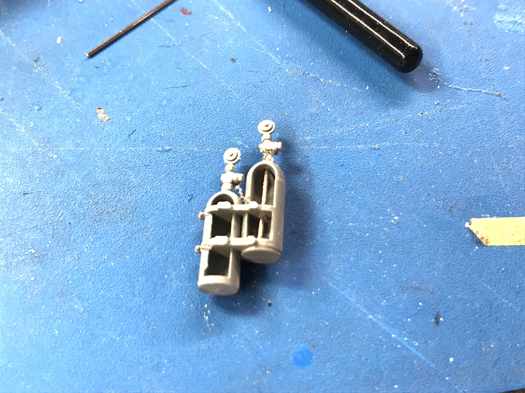
I then bent another piece of wire to replace the plastic piece. I CA'd this in place and then used some Bondic UV curing resin to add some bulk. I then primed it.

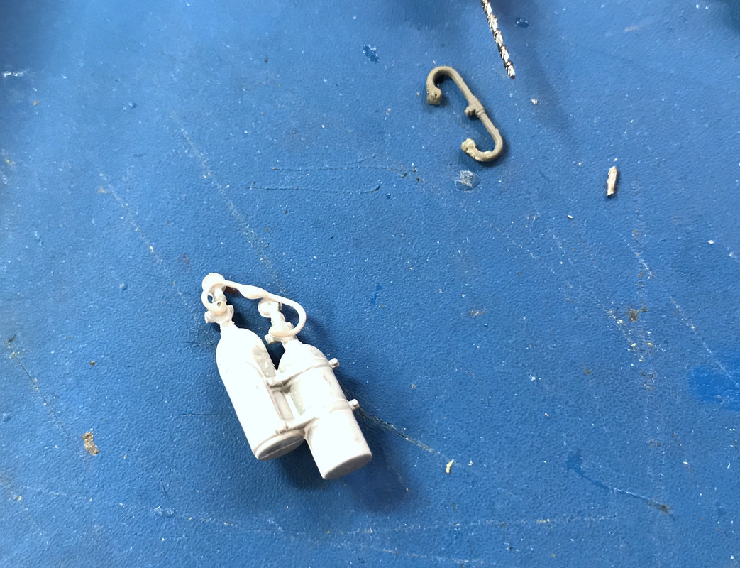
I painted the bottles red and then Dullcoated it in preparation for my artificial brass technique, which is Molotow Chrome Pen overlaid with Tamiya Clear Yellow and maybe a little Red. It's a remarkable metallic finish that doesn't have the grain that metallic paints do. This was drying at the end of the day. If you look up my USS Essex build on this website you can see how I used this technique on the props with reasonable success. I couldn't find brass aftermarket props so I did the next best thing.

Later, as you'll see I tried the fighting room floor in place since I suspected that it completely obscured the fire bottles over which I spent all this time.

I then weathered the engine compartment walls, floor, engine, etc. I initially used Tamiya Clear Smoke for the oil stains at the bottom. I then used AK wash thinned with alcohol and then went back and overpainted all the excessive areas with white. I just wanted it messy and messy it is. I erred in this. I should have sealed the white with a non-water-based clear coat. The AK quickly started dissolving the white making a mess. I recovered, but it wasn't the best way to approch this.

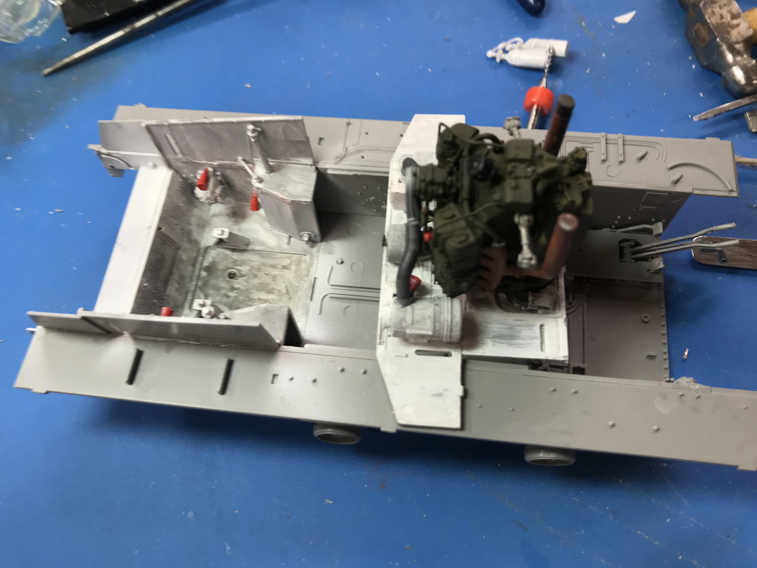
I had removed the fire bottles completely since they made putting the firewall in correctly very difficult. It should have been left until the engine bay was complete. I glued in the engine and ran into a problem getting the fan drive shafts aligned with their gear boxes. I ended up having one break and fly into the quantum rift. 

Speaking of quantum rift... when I went looking for the tiny other universal joint end of the shaft I found the Magneto.

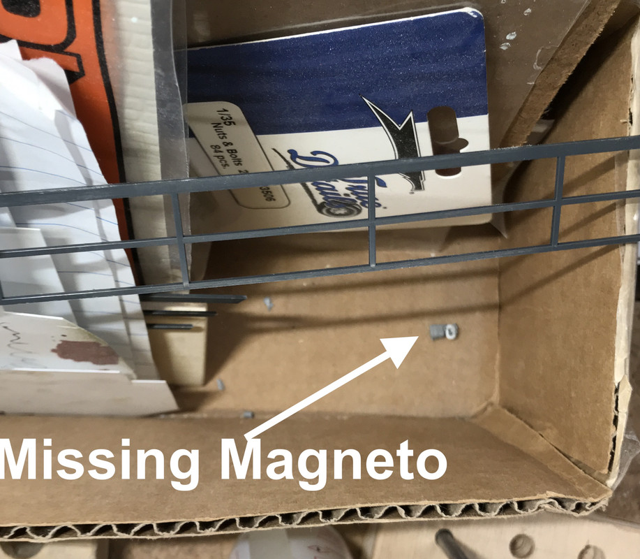
It was hiding in a box that sits on the back of my work table. That little piece cost me almost an hour of build time between the scratch-building and part search. Oh well...

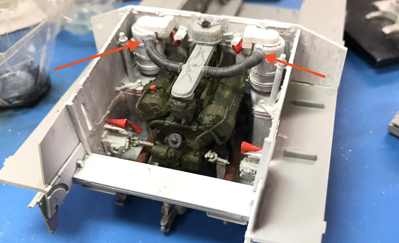
I was having trouble getting the intake ducts to couple with the air cleaners so I cut some 1/8" Plastruct rod, drilled a small hole for the nib on the duct and put them in. Makes a decent installation. I noted yesterday that you should also leave these tubes off the engine until it's installed in the engine bay so you won't be fighting fully cured glue joints. The arrows point out these spacers. You can see the broken fan shaft. I'll will keep looking for it and find it when it decides to come back to this dimension.

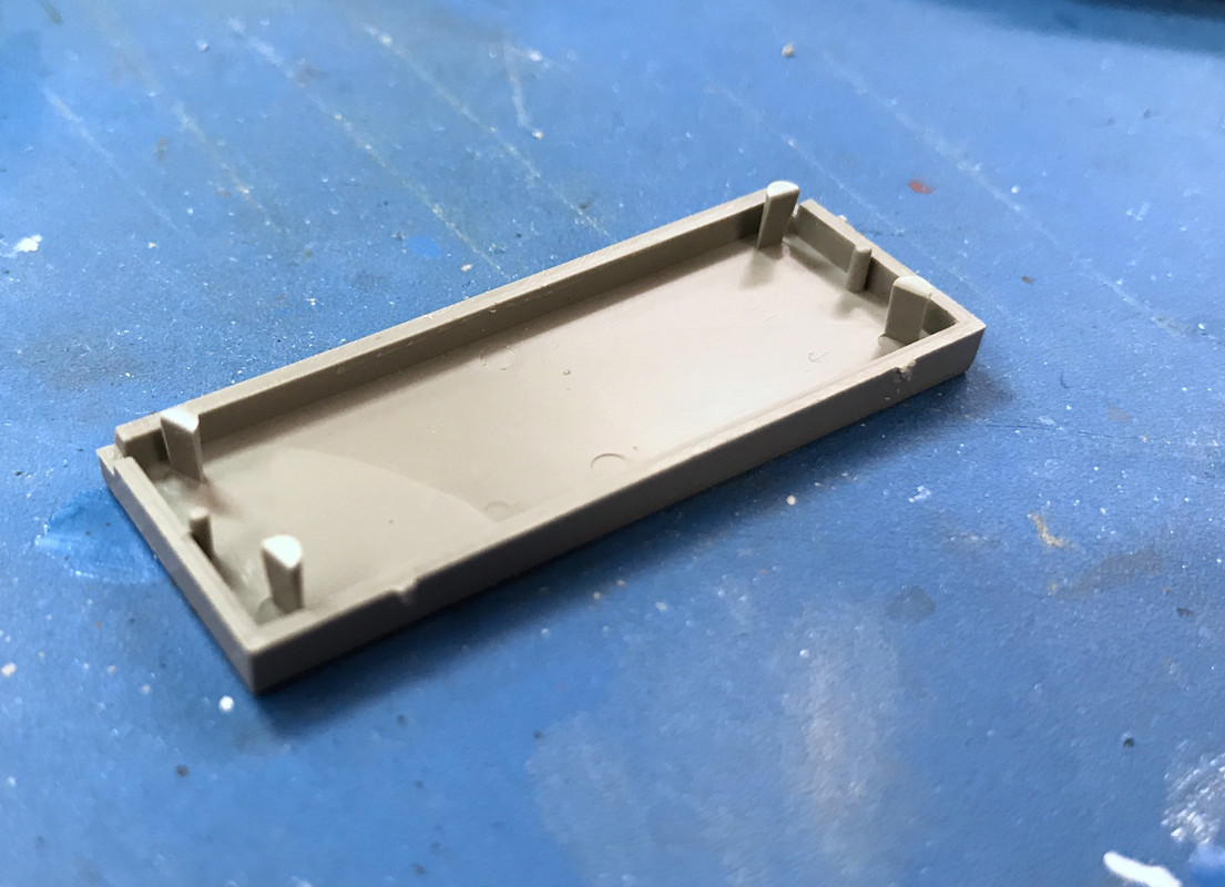
It was time to build the radiator. The radiator consists of the inner half with the fans and their shrouds, and the outer half that has a set of louvers to protect the fan from battle damage. The radiator surface is an example of fabulous mold making. There are tiny grooves simulating the core. Unfortunately, it's entirely hidden so don't waste your time trying to make it look right.

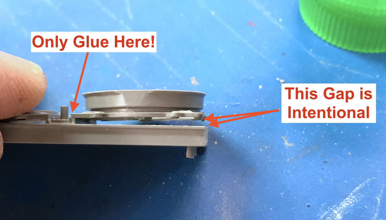
I spent probably 10 minutes trying to figure out how the fan frame glues to the radiator face. It turns out that it glues on one edge only. After I test fit it to the model did it become clear why this is. Obviously, gluing to one edge and having it stand proud all around didn't make sense and it took a lot of fiddling to get it right.

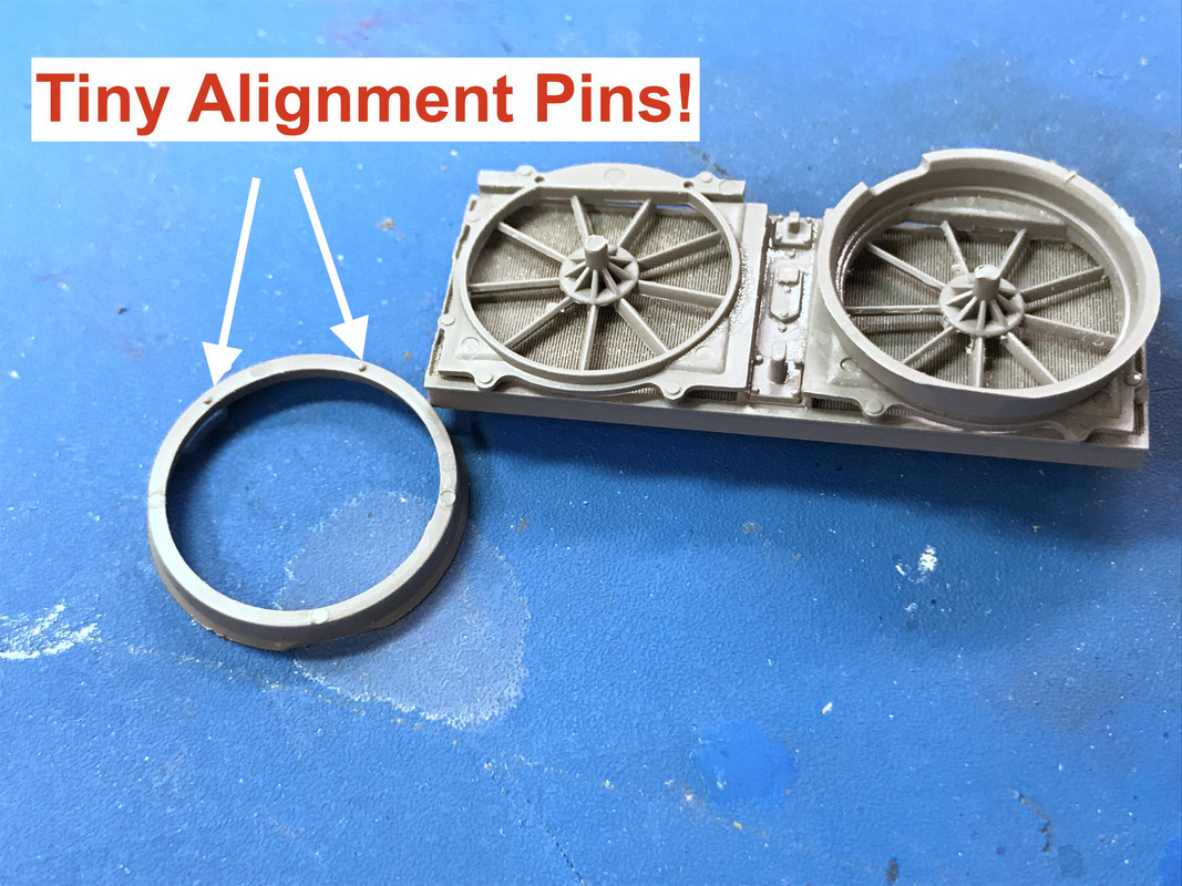
One of my pet peeves about Ryefield engineering is they are very stingy on the diameter and depth of their alignment pins. This picture shows what I mean. It took too much messing around to have those pins find their locations when glue was on the joint. The glue can almost melt the pins before you get them assembled. There's no reason why they couldn't have been more robust.

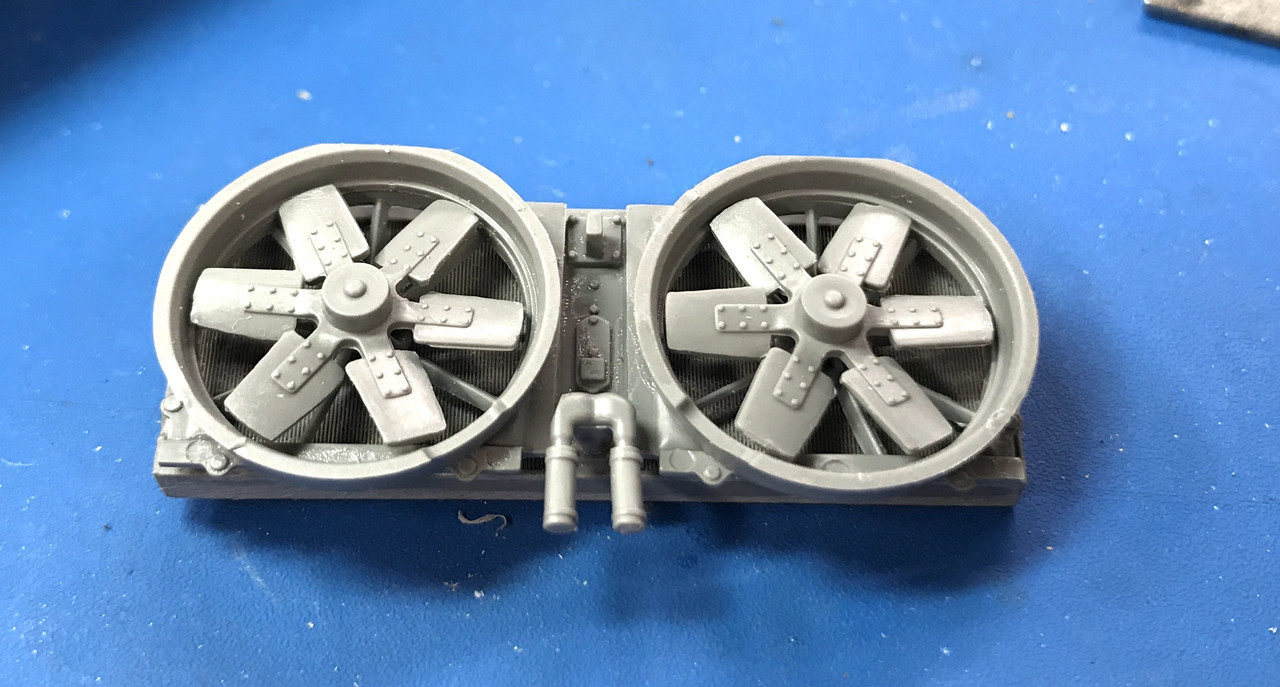
The fans themselves went on very easily with a huge lug. Additionally there was the coolant connecting pipe that aligns with the little "Y" stub on the water pmp on the block. You can't see this connection when it's all installed. It's at the bottom of the engine and obscured by the radiator assembly.

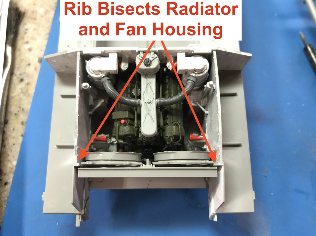
I test assembled this and then I saw why the gap exists. There is a rib on the hull side piece that lies between the radiator and the fan frame. The instructions don't show this very clearly and I can imagine people gluing the frame on solidly all the way around only to find out that it's wrong. What tipped me off was it wouldn't lie sqaure when the single rib was glued. And there was a tiny alignment lug on the frame that intersected a notch on the radiator, so you knew it went there.

Both the inner and other radiator parts had huge ejection pin debris. They're so big they looked like standoffs. They're not and they needed to come off.

The outer radiator had another head scratcher. The louvers only glue by four tiny pins AND it rasises it off the radiator body. It's supposed to and it's very fragile. On top of this louver is another deflector that doesn't glue to the radiator. It only glues to the louver. Took a while to figure this out and get it right. This is curing over the weekend.

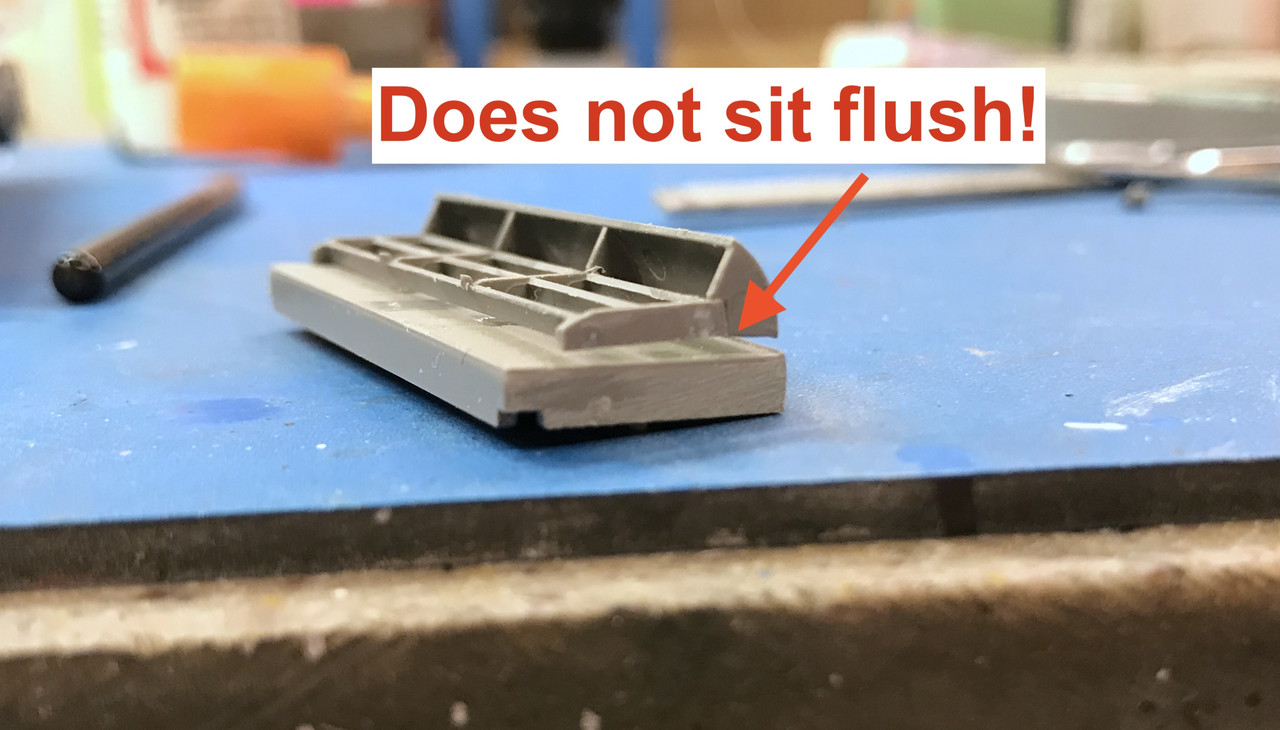
I'm going to airbrush the radiators before putting them on the model. Monday! So here's the fighting floor dropped in for a looksy. Notice, it not only covers where the fire bottles sit, but also covers the drive shaft, and the extra piping they want you to add from those heater coil tubes. I may add the piping just for fun, but it's not much of a value-added-activity. The floor doesn't actually sit flush like this. It sits on a frame that raises it up a bit.

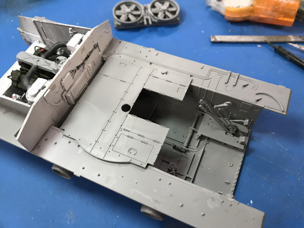
The rectangular opening in the floor will be to display one of the magazines with ammo in place. This was the "wet storage" version of the Sherman with had the shells immersed in anti-freeze to prevent cooking off in case of fire. (Thus the 76W designation). It was also interesting to note the fire suppression system in the engine compartment. The Sherman was well-engineered and was reasonably comfortable piece of armor to fight in. After this project, I'm really itching to do the Ryefield Abrams with interior just to fully understand the evolution of armor over the ensuing years.

  • Member since
    July 2014
  • From: Rifle, CO. USA
Posted by M1GarandFan on Saturday, August 8, 2020 12:20 PM

I've been following this build with great interest considering I love Shermans and Rye has a pretty good reputation. That said, there is no way I would attempt this kit with all of its tiny delicate parts. I've had enough of kit makers molding every single part separately in the cause of realism. I just think they are being lazy not molding some small items as part of a larger piece. I built Takom's jeep and trailer and that little engine had about 25 separate parts. Then, assuming you permanently attach the hood (bonnet), nothing is really visible after all that work. I guess I just don't appreciate all that exquisite detail, but my hat's off to those of you who persevere. OK. That's my rant for today. Sorry for taking up your time.

  • Member since
    September 2018
  • From: Vancouver, Washington USA
Posted by Sergeant on Saturday, August 8, 2020 1:01 PM

M1GarandFan

I've been following this build with great interest considering I love Shermans and Rye has a pretty good reputation. That said, there is no way I would attempt this kit with all of its tiny delicate parts. I've had enough of kit makers molding every single part separately in the cause of realism. I just think they are being lazy not molding some small items as part of a larger piece. I built Takom's jeep and trailer and that little engine had about 25 separate parts. Then, assuming you permanently attach the hood (bonnet), nothing is really visible after all that work. I guess I just don't appreciate all that exquisite detail, but my hat's off to those of you who persevere. OK. That's my rant for today. Sorry for taking up your time.


John, I feel pretty much the same way you do. Builder 2010 is doing an outstanding job of assembly, but unless it will be seen, what is the point?

Harold

  • Member since
    July 2014
  • From: Rifle, CO. USA
Posted by M1GarandFan on Saturday, August 8, 2020 1:39 PM

Thanks, Harold.

  • Member since
    March 2012
  • From: Louisville, KY
Posted by Builder 2010 on Saturday, August 8, 2020 2:50 PM
I can't argue with your logic. Some of the work is just for the sake of building it and testing your chops to see if you can pull it off. I am planning on displaying the model in such a way as to expose as much as possible. That said, things laying at the bottom of the engine compartment or under the floor decking really won't be viewable even if the model is exploded. I'm thinking of mounting the parts over a mirror so the undersides of the turret and upper hull are visible. We'll see how it goes.
  • Member since
    September 2018
  • From: Vancouver, Washington USA
Posted by Sergeant on Saturday, August 8, 2020 3:52 PM

Builder 2010
I can't argue with your logic. Some of the work is just for the sake of building it and testing your chops to see if you can pull it off. I am planning on displaying the model in such a way as to expose as much as possible. That said, things laying at the bottom of the engine compartment or under the floor decking really won't be viewable even if the model is exploded. I'm thinking of mounting the parts over a mirror so the undersides of the turret and upper hull are visible. We'll see how it goes.
 

Regardless of my philosophical reasons for not doing something, you are doing an great job and I respect the fact you want to keep developing your modeling skills. I feel the same way.

Harold

  • Member since
    July 2014
  • From: Rifle, CO. USA
Posted by M1GarandFan on Saturday, August 8, 2020 4:08 PM

Well, I absolutely agree with Harold. Your display idea is a good one.

  • Member since
    November 2009
  • From: SW Virginia
Posted by Gamera on Saturday, August 8, 2020 6:38 PM

Wow, that looks incredible!!!

I got about 75% of the way though the MiniArt T-44 with the complete interior and ended up burnt out and put her back in the box. I really hope you're able to finish this, it's pretty darn epic!

"I dream in fire but work in clay." -Arthur Machen


  • Member since
    February 2011
Posted by GreySnake on Monday, August 10, 2020 12:25 PM
Really great work and I’m impressed with how much work you are getting done. The engine came out really well. I know the frustration of losing a piece making a replacement and then finding the missing piece.  
  • Member since
    March 2012
  • From: Louisville, KY
Posted by Builder 2010 on Monday, August 10, 2020 10:00 PM

I appreciate all the comments. If I'm noted for anything, I always finish what I've started. This Sherman is going to get done. I didn't have much time since I took the 2013 LaCrosse in for a much-needed oil change. The cars are being driven almost 0% with almost no driving these days, it still needed doing.

That said, I got something done for my hour in the basement. The radiator, fans, belt drives and top radiator line are now in.

Instead of following the instructions, which had you gluing the front portion of the radiator in first and the back portion up to it, I glued both halves together and then glued it all in. Before gluing I masked the glue edges and airbrushed the whole deal the Life Color Haze Gray. I then brush painted the fans semi-gloss black. I brush painted the belts Tamiya Rubber Black and then the hubs the semi-gloss black.

Here is the radiator assembly in place.

I then had to finagle the belts into position. This was troublesome because of the clearances at the gear boxes. Having the hole in the correct location on one of the boxes for the pin on the belt drive, really wasn't much help. In fact, it was easier with the other one where I clipped the pin off since there was no hole for it. I was just able to swing it into place and then glue it. I finally got them in and had to retouch the paint a bit.

The top radiator hoses were supposed to intersect with the piping coming off the intake manifold, but they were about 1/32" short. I decided to do a little micro-surgery to add some 1 mm Albion Metals micro-tubing to close the gap. I first had to drill the ends of the styrene radiator piping. I started with a pin-*** from a pair of dividers, then drill with the 0.022" carbide and finally opened up to 0.037" for the Albion Tubing. I was very pleased with myself that I was able to center the drilling and not break out of the side.

I cut Albion tubing with a razor blade. You roll the blade across the tubing a couple of times and the piece breaks off. You need to keep the blade perpendicular to the tubing. To do this easily, just watch the reflection of the tubing in the blade. When it appears that the tube is still going straight through the blade, you squared up. The key is to keep it that way while you roll it back and forth. Don't press hard! If you do so the part will come off with energy and we all know what that means. Soft works better.

To get the tubing into the holes, it's best to use a guide in the tube to align it in the hole and then push it in. In this case I used a 0.032" carbide drill. It took a couple of tries, but miraculously I did not lose any of my cut pieces.

With the added pipes, the lines now touched. I will paint this tubing tomorrow. Again, these are details only a modeling nut would ever notice, but believe me, the guys in my modeling club are a tough crowd.

Here's a reverse view that shows the whole deal including the fan drives. Yellow arrows point out the drives. I still have to weather the radiators, will do tomorrow.

Albion tubing is ridiculously small with very thin walls, and is the only thing I've found that can give you reasonable looking terminations for scratch-building piping using .5mm solder wire. The tubing comes in an assortment of telescoping tubing in 1mm, .8mm, .6mm., .4mm and .2mm. The small one is so small that it's almost non-usable.

  • Member since
    November 2009
  • From: SW Virginia
Posted by Gamera on Tuesday, August 11, 2020 7:27 AM

I love that, great work! I know it sounds trite but I'd swear it were a 1/16th scale model instead of 1/35th, that's some detail packed in there. You sir have steadier hands than I! 

"I dream in fire but work in clay." -Arthur Machen


  • Member since
    March 2012
  • From: Louisville, KY
Posted by Builder 2010 on Tuesday, August 11, 2020 7:58 PM

Thanks! I'm not so sure about the steady hands. Sometimes it's a real battle, especially if I'm hungry. One day last year I was particularly shaky. Not only did a I have lunch (I was hungrey) but I finished it off with a shot of 18 year-old Elijah Craig Bourbon. That did the trick. Steadied me right out.

Today's work, the transmission tested those hands to the limit. I only didn't put on one crazy small part. Not because I couldn't handle it, but because the gluing surface was so small as to be completely ineffective and it wasn't worth the trouble. Before I did that, I finished up the radiators. I painted the connecting pipe with my extensions and I aged the rest with low-odor mineral spirits + Tamiya Panel Accent Black. This didn't dissolve the water-based paint underneath. I didn't overdo it; just a little to break the newness. I picked out the pipe connectors with the Molotow Chrome Pen. With this the engine compartment is complete.

Now onto the transmission. This assembly includes the trans, a generator driven by belt off the drive shaft, the ventilation distribution apparatus and the grease gun portable machine gun. 

This assembly consists of 48 parts! That's a huge parts count for such a small structure. Here's what the instructions look like. This was two out of the five steps to build it.

And one of those parts look like this:

I did not use this part. It was the only one.

The ventilation system was a six-part affair not including the machine gun. That gun's barrel broke off while still in the sprue. There are others so I measured their barrels and it came out to a convenient 0.022" of which I have the drill and the rod, so I drilled it and replaced it.

There was an intricate folded piece of PE with some plastic parts added. I had to reinforce with CA and Bondic to keep it all from unfolding and eventually breaking.

The trans' back end was ridiculous. Lots and lots of tiny parts with specific orientations. It was actually fun and was a challenge. The lever? I'm not quite sure what it actually does. It may be a parking brake. I'd have to find a Sherman operations manual to figure it out. (Editors update: That's the gear shift lever! DOH! Of course it would be with all the mechanism attached to it) The gear shift nestles between bunch of brackets as does the operating linkage below it. Solvent cement wasn't cutting it. I eventually succumbed to cross-drilling the whole deal and pinning it with phos-bronze.

Behind the trans goes this generator thing. Again, I'm not sure why the generator is attached to the rear of the transmission and not in the engine bay. (Editors Note 2: Yes, it is the generator, and I still don't know why they put it in the fighting compartment) It has a belt that will be intersected with the drive shaft. The guard and the gerator were difficult to build. That's because the generator was suspended on solid material only on one side. The other side has a scale-sized (read very fine and thin) adjustment link which would support the other side. That link broke in my many attempts to correctly install it, and again, I was forced to make a link out of phos-bronze and used Bondic to lock it all together.

These very closeup shots make the stuff look very rough, but you really can't see it with the naked eye and it's not painted yet.

So here is the finished transmission. The front gear case glues to this bulkhead, and then this gets glued to the hull front. Only then will the steering levers be attached. They attached to the cross shaft on the bulkhead top.

The front gear case gets built tomorrow. When I fasten this to the hull, I might spray that part the base white color. Also, I put a coat of Molotow Chrome on the fire bottles' piping. This will be nice and dry to tomorrow so I'll put the clear colors over it to simulate the brass.

Found this diagram that not only names all the parts, but shows the coloration of the generator assembly that contrasts to the rest of the interior painting.

Onward and upward.


JOIN OUR COMMUNITY!

Our community is FREE to join. To participate you must either login or register for an account.

SEARCH FORUMS
FREE NEWSLETTER
By signing up you may also receive reader surveys and occasional special offers. We do not sell, rent or trade our email lists. View our Privacy Policy.