SEARCH FINESCALE.COM

Enter keywords or a search phrase below:

WIP Scratch build 1/10 Sd.Kfz 9 Famo

14916 views
29 replies
1 rating 2 rating 3 rating 4 rating 5 rating
  • Member since
    November 2014
WIP Scratch build 1/10 Sd.Kfz 9 Famo
Posted by Famo Guy on Monday, November 3, 2014 9:00 AM

Hi,

as announced in my Hello from Germany post,
I would like to introduce my 1/10 Sd.Kfz 9 Famo scratch built project. Please turn a blind eye regarding my grammar and vocabulary.
The goal of my project is to create a very detailed scale model but I dont know how good I could create it. When I started I had no experience with machining and so on. But Im ready to invest lot of time and I dont want a ready model very soon. To make a long story short but to give you the chance to unterstand the first pictures I've to explain what happend until now.
The project has 3 phases until today.

Phase 1: Around 2007. The Famo should be 1/16 to fit to my Tiger. A lot of 3D files has been created. I intended to cast the tracks by myself with a homemade rotation cast machine. So i had to create a prototype of a track link.

Phase 2: Around 2009. Rumours told me there is a 1/16 Famo model in preparation to be trown on the market. So my motivation to continue with this scale was'nt the same as before. Additionally i found that creating a steering gear working like the original Famo very attractive. Ok, lets start over with 1/10. Main activities in this phase are focused on the steering gear. Some difficult details and a move and becoming a father stopped the project.

Phase3 : Around 2014. Although i worked on the front wheels in the meantime, the concentrated work continued in summer of 2014. To continue my project without being confronted with hard bodied problems i decided to work on the 3D-Model of the front tyre to be printed an manufactured by a professional model company. I also decided to order a company to cast the tracks.

Because it takes lot of time to explain every picture in detail with English, I only comment short and you are welcome to ask if you need more information.

So lets start with phase 1 in the next post.

Bye Matt

  • Member since
    November 2014
Posted by Famo Guy on Tuesday, November 4, 2014 8:12 AM

Phase 1:

As a basis i use a Tamiya 1/35 model (with Sd.Anh 116) and the following books:

- "Halbkettenfahrzeuge des deutschen Heeres"

- Nuts & Bolts Vol. 12

- Military Machine Famo 18t

- Waffenarsenal Band 36

- Copy of Maintainance book D671/1 D671/2

- lot of pictures from the internet

I would like to build the early F3 version of the Sd.Kfz 9.

Difference of the early (left) and the later right) track link for example:

I create 1/1 in CAD. Some pictures of 3D parts:

Front axle and rim:

Front axle:

Hood and grill:

Grill with Famo-Logo:

Early draw of track links and drive wheel to check dimensions:

3D prototype of the track link. To create a mold for casting i had to create a prototype. The design takes into account that i could create the parts easely.

Parts of the 3D prototype:

After planning and supplying with material i have startet my milling machine (Minimill X2).

Step by step milling of the guiding tooth:

The flat part of the link:

So far all parts until now:

Assembling has been startet.

To see more details a primer has been applied:

The flat parts can be disconnected to enable the creation of a sillicon mold.

Thats phase 1. Remember, lot of things will change in the next phase...

  • Member since
    November 2014
Posted by Famo Guy on Tuesday, November 4, 2014 8:13 AM

Phase 2:

The prototype of the track link was lot of work and it hurts to throw it away.
Changing the scale from 1/16 to 1/10 ! Why?

I demand a lot from this project without knowing whether I'm able to get it to a satisfying end. I invest time and money (I did it and I'm willing to continue) but I knew there will be 1/16 models of the Famo on the market very soon. This increased my motivation not to much.
Another reason was the idea of creating the steering gear with the same function as the original. And this needs a bigger scale than 1/16!

So lets focus on the principal accused - the steering gear:
I spent hours to analyse my documentation - mainly the maintainance manuals. The gear is like a Torsen differential where the gear ratio inside can be influenced with brakes outside the gear.

Original parts of the steering gear:


My 3D model :


<embed src="https://www.youtube.com/v/Z6LtQWaX958&hl=de&fs=1&rel=0" type="application/x-shockwave-flash" allowscriptaccess="always" allowfullscreen="true" width="425" height="344"></embed>


Reworking of a steel gear to fit to the rotating diff housing:

Because I had no experience with maching lots of parts where made for the trashcan. But I improved over time..

After weeks of machining I had a couple of part:


First assembling:

Looks not too bad and it fits very well.

How the pinions and the axles are related inside the diff:


After additional days of working i could assemble all the parts i had until now. Fits good - although the clearance could be a little bit greater.


Inside view:


In the meantime I focused on the brakes. To get close to the original brakes I wanted to have drum brakes. I found that I could rework clutches from nitro car model engines.

After I got rid of the pinion I used solder (dont know the name in Englisch, maybe hard soldering ?) to fix a brass disk:


Fitting:


I realised that my diff-gear was in need of a housing. Like the original it consists of 3 main parts wich enclose 2 chambers: one for the diff gear and the other for the switching gear (is it called gear box ?). Althouh not in mind when I startet with the gear now i wanted a switching gear with at least 2 gears.
After checking the room it was clear: no space for 3 gears.

Preparation of the 3 massive aluminum blocks.


After 8 hours of milling - the middle part:


The cover of the housing:


All 3 parts with the first holes for the ball bearing:


Time to place the gear within the housing.


Now for the gear box:
A lot of work with this little part:


This part is to hook into the turning disk and to move the disk to hook the pins into the holes of the one or another one gear.


All togehter:


So far so good. Now I had to create the base for the brakes or care about some fixations of the brass gears.
But I had to move to a new flat ... then my wife and me got our son ... No time for gears ;)

Thats the end of phase 2. Lets see how it continues...

Bye Matt

  • Member since
    November 2014
Posted by Famo Guy on Tuesday, November 4, 2014 8:15 AM

Phase 3: The front tyres! Holy Jesus, I'm sure I cannot explain enough how much time I spent with theese chunks of rubber. As I mentioned before I want a very accurate model and in my opinion the front tyres of the Famo have a significant impact of the overall impression. There are some 1/10 tyres I found in some shops but they look ... to be polite : not so good (terrible). With the books and pictures I had until this time and the tyre from the 1/35 Tamiya kit I startet to create a 3D model of the tyre. But the longer I analysed this the more I found there are more details which I could'nt recognize enough. There are details on the pattern itself, the overall shape of the tyre with the dimensions and bends had to be transfered to the model and the signs and markings on the sidewall where important. I spent hours of research in the internet, requested information from museums and the company who produced the tyre in the thirties (Continental) but no luck. But one american museum answered my request with pictures which caused my pulse went to 180. They have shown me the writings under the Continental writing.
Now I think I've enough information but I'm not 100% sure. On the other hand if there would be more little writings on the side wall, the question is could this be printet with a 3D printer with the desired accuracy.

If one of you could provide information about this tyre I would highly appretiate it !!! Its from Continental and the dimension is 12.75 - 20 Extra HD

Some pictures from my model (with some rendering errors) and one from the original tyre to compare:


Here you can see the 3D model behind the renderings:


One of the mysterious writings. The others are "MADE IN GERMANY" and "DEUTSCHES FABRIKAT". In the background the Continental sign can bee seen:


I'm really happy with this because it looks almost like the original. I think (actually I'm sure) there is no other model of this tyre with this details and the overall impression like the original - anyway, I,ve not seen any other. But this is important because the production of the tyre will be very expensive.
Now I prepare for 3D printing and do very little corrections on the overall shape.

Thats it for now folks. Hope that there will be no such big breaks in the future like the 2 before. So stay tuned....

Bye Matt

  • Member since
    February 2011
  • From: St louis
Posted by Raualduke on Tuesday, November 4, 2014 9:44 AM

What an incredibly ambitious project.I'll be following this,keep us posted, and good luck. Mike

  • Member since
    December 2012
Posted by RX7850 on Tuesday, November 4, 2014 9:44 AM

Umm. Wow!

You got some serious machinist  skills.

Hope you are able to see it to completion.

  • Member since
    February 2011
  • From: St louis
Posted by Raualduke on Tuesday, November 4, 2014 2:02 PM

If you don't mind my asking, what type of milling machine are you using

  • Member since
    November 2014
Posted by Famo Guy on Wednesday, November 5, 2014 2:23 AM

I work on a Mini Mill X2 with some modifications. First a digital Z-axis read out with display was mounted. Later I installed a belt drive  upgrade kit - much better than the original vinyl gears.

Another accessories are:

- MT3 Mill chuck set

- high precision vice

- Rotary table with dividing plate

- a boring head (also used for lathing jobs)

- a dial gauge with stand

Bye Matt

  • Member since
    February 2011
  • From: St louis
Posted by Raualduke on Wednesday, November 5, 2014 10:42 AM

Thanks for the info. It's looking great

  • Member since
    April 2013
Posted by KnightTemplar5150 on Thursday, November 6, 2014 9:35 PM
Excellent work and great insight into the techniques you are using on this project. Looking forward to seeing more of your work!
  • Member since
    July 2014
Posted by modelcrazy on Thursday, November 6, 2014 10:04 PM

That's incredible.  I am anxious to see your progress.  Very nice work sir.

Steve

Steve

Building a kit from your stash is like cutting a head off a Hydra, two more take it's place.


http://www.spamodeler.com/forum/

  • Member since
    November 2014
Posted by prokofi5 on Friday, November 7, 2014 7:08 PM

That's really impressive. Looking forward to seeing more.

  • Member since
    January 2006
  • From: Pineapple Country, Queensland, Australia
Posted by Wirraway on Tuesday, November 11, 2014 4:04 AM

Well I am flabbergasted.  You are a truly talented modeller Sir.

"Growing old is inevitable; growing up is optional"

" A hobby should pass the time - not fill it"  -Norman Bates


GIF animations generator gifup.com

PVI
  • Member since
    May 2014
  • From: Wisconsin
Posted by PVI on Thursday, November 13, 2014 2:56 AM

WOAH! That's awesome!

  • Member since
    January 2003
  • From: Washington State
Posted by leemitcheltree on Thursday, November 13, 2014 10:37 PM

Holy freakin moly!!!!!!!

I'm an engineer at the largest airline manufacturer in the world.......and I am SO impressed with your skill and passion.  Seriously.

I wait - eagerly - for your next installment!!!!

Cheers, LeeTree
Remember, Safety Fast!!!

  • Member since
    March 2008
Posted by Caveman on Friday, November 14, 2014 11:39 PM

I don't have the words.  I will gladly follow this project in absolute awe.  Hats off to you sir.

  • Member since
    November 2014
Posted by Famo Guy on Saturday, February 7, 2015 8:14 AM

Thanks again for your compliments !

In the meantime I prepared some samples of the tyre model to be printed with shapeways most detailed material "Ultra Frosted Detail".

Here you can see the results:

I'm contended with the pattern, all details and round parts are printed in a satisfying quality.

But the markings on the sidewall you can hardly see even less feel the structures.

Until now I've been looking for a solution. Maybe a better printing technology could help...

To continue on the project I'm working on other 3D models, parts of the front axle or the track link for example.

With this models I can check the price of 3d printing and casting.

The following part is a mount for the leaf spring at the axle.

3D printing is under 10 EUR but creation of the casting mold costs about 80 EUR. Each brass casted part is about 5 EUR and I need 2 for one Famo.

Now I can weigh up the options: pay the money and get very good parts very easely, save the money and turn on the mill and solder. Maybe one additional option is to think about a group build where more people could share the cost. But I fear it's not easy to find enough people who are as nuts as me...

I'll finish the track link very soon and because I'll need lots of links the cost for the casting mold is much cheaper for each casted link.

So stay tuned.

Bye Matt

  • Member since
    November 2009
Posted by artworks2 on Saturday, February 7, 2015 12:39 PM

Nothing like seeing mill work. There aren't many mill writes these days with mold casting and such I worked in a foundry years ago. Rapid prototyping parts is catching on but still need someone to clean up the flashing. Nice work.

  • Member since
    November 2014
Posted by Famo Guy on Sunday, October 1, 2017 11:20 AM

Hi folks,

long time since my last post but i did some work in the background. Now I'm at a point to think about how to realize specific parts. In my last post I mentioned the option for a group built. Now I would like to request more specifically.

Are some of you interessted in a group built?

How I think about this:

Some parts can be created easier using modern technologies like 3d printing or cnc milling or machining. But this will cost more money. The more people pay for one specific part the cheaper the part will be. Additionally the parts will have more details and you don't have to assemble more complex parts from many little parts.

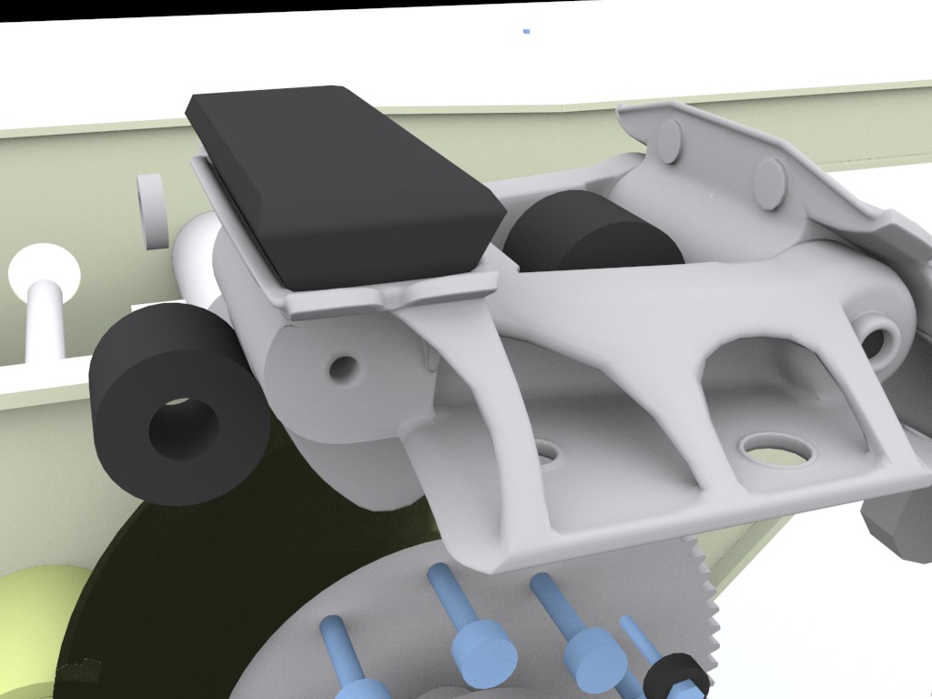
I've been working on the drive wheel since a couple of weeks. 2 photos to show how it looks on the real thing:

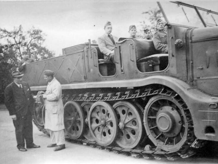
(early version of the drive wheel cover - which I intend to realise)


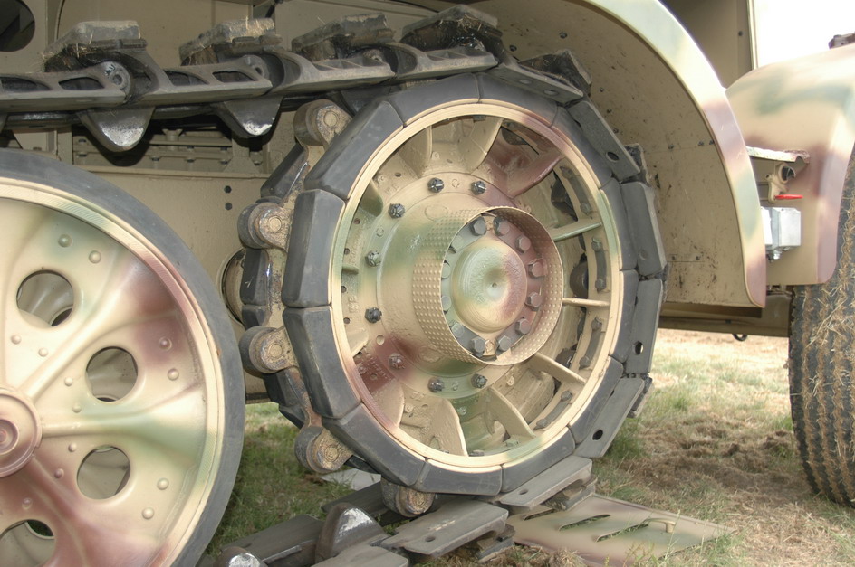
(detail view but with a later version of the cover)


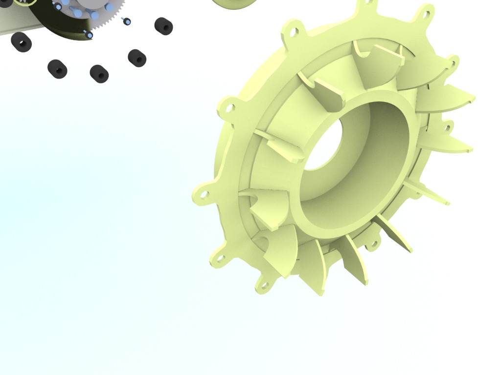
This is how my 3d model looks at the moment.

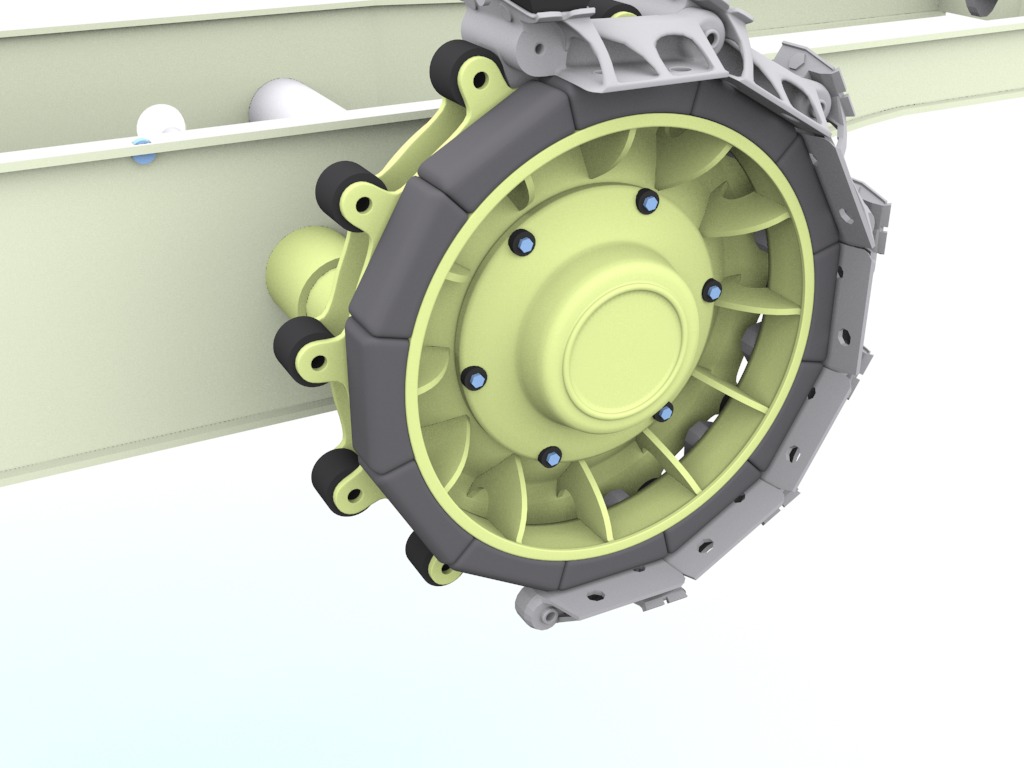
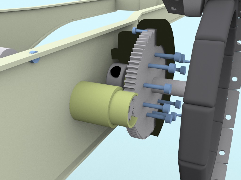
(the wheels is mounted on a spur gear wich runs via ball bearings on a fixed axle)
 

With this example part I would like to show the difference between the differnt ways for creation.

One way ist to assemble the drive wheel of a machined (lathe) brass base part and some cnc made parts from brass sheet. Theese parts have to be soldered together wich could be a very frustrating job. Following pic shows thees parts.


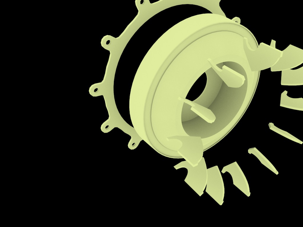
For the other way we need a 3d modell which has to be 3d printed (shapeways for example) to get a prototype. This is needed by a casting company to create a die. This way one could bring all details to the model (like embossing details on the surface).
Here you can see how this casted part could look like (without surface details):


Costs for this way :
1. 3d printing depending on the material and size
2. Creating the die (about 80 -100 EUR) depending on the complexity.
3. Cost per casted part.

This way I intend to create the track links because I need about 80 pieces for one Famo.

This rendering shows the 3d track link in an almost finished version.


Some more information about how I intend to make the model from the todays point of view:

The frame: made of cnc cutted brass sheets (1,2 mm) and brass pipes soldered together

Rubber parts (front tires, track pads, rings on the wheels) made from cold vulcanising rubber material. (dies are needed).

Motor and gear box : I think, my version with the steering gear is too experimental and a classic concept with 2 motors should be used.

The running wheels : there are 3 different version on one Famo. I intent theese wheels to be castet in brass.

The rims of the front wheels: like the original I would like to create the 3 parts of the rim and the hub as seperated parts (castet in brass)

The car body: made of brass or bronce sheets using different techniques like:

for the fenders pressing metal sheets.

for other parts techniques inspired by Gerald Wingrove. Here are some details.

Before I write too much please let me know what you think. This should be a base to discuss the possibilities.

Bye

Matt

  • Member since
    November 2014
Posted by Famo Guy on Monday, October 9, 2017 4:36 AM

Hello again,

now I've finished the technical design of the drive wheel. Sizing of the spur gears (ratio and distance of the two axles where important) where an iterativ process. Fortunatly I could download 3d-files from the shop.

I had to find a solution for the fixed 8mm axle for the drive wheel. The big spur gear needs 2 bearing seats to move free on the axle. The drive wheel is mounted with screws on the spur gear. Some bushes to keep the parts in position where placed and the drive wheel housing was created. the housing will be made of 2 parts from the lathe.

The drive wheel has an additional ball bearing for aditional stability.

Here you can see a section view:


To check the geometry of the tracklink and the rollers of the drive wheel I used the animation features of my 3d software:

Another view of the track link positoned on the rubber pads and the rollers:


Bye Matt

  • Member since
    January 2016
  • From: A Galaxy Far, Far Away
Posted by Hunter on Sunday, October 22, 2017 10:02 AM

Wow!! Absolutely amazing. This is one heck of a WiP, and your skill level is awesome. So well planned and executed. I can't wait to see it done.

Hunter 


  • Member since
    June 2014
  • From: New Braunfels , Texas
Posted by Tanker - Builder on Monday, October 23, 2017 10:13 AM

Hmmmmm;

 All I can say , is in capitol letters .WOW ! ! 

 T.B.

  • Member since
    November 2017
Posted by Met5 on Thursday, November 2, 2017 6:48 PM

Hello! Do you have finally solved the dimensioning of the wheels of the Famo? I am also looking for a certain value. 

did you understand what 12.75 R20 means ?!


Thanks and kind regards


Fabio

  • Member since
    November 2014
Posted by Famo Guy on Sunday, August 4, 2019 10:42 AM

Hi Fabio,

your post is long time ago but the lack of time (became father a second time) and trouble with my account delayed my activities.

But some days ago I found what you (and me to confirm my model) where looking for.

While I was walking with my son I saw a excavator with writings on his wheels : 12.5 - 20 -> I was electrified - almost the same writing like on Famos wheels. The next day I put a folding rule in the bag to take dimensions.

The problem I had until now was: actually I understand how to calculate tyre dimensions but the result does not fit to the dimensions I figured out via checking the Tamiya 1/35 wheel and lots of pics. The rule is: 12.75 is the width of the tread and the thickness is 80% of the width. So the diameter should be 50.8 cm (20 inches) + 2 x 80% of 32.385 cm(12.75 inches) which is 102.6 cm. This is too small. One day I found that the additional writing "EXTRA" means some modification of the dimensions but no exact rule.

Now I'm sure this means 100% of the width instead of 80%. So the diameter is 50.8 cm + 2 x 32.385 cm = 115.57 cm. And this fits very well to the dimension of my model tyre.

Additional I found this info paper from 1939 which has measures of all kinds of tyres used in Germany in this time : http://delibra.bg.polsl.pl/Content/28300/BCPS_31954_1939_Technisches-Handbuch.pdf

Page 49 !!!

I will post some progress on my project very soon.

Bye Matt

  • Member since
    February 2020
Posted by JCarducci on Sunday, February 9, 2020 11:41 AM

Matt how is your 1:10 Famo project proceeding? I was working with a fello in Germany to build one of these but he had to stop for health reasons. I have the parts from his progress and they are quite good so far but I do not know how they compare to your standards.

You had asked who might be interested in a group project. I have some metal casting and metal forming capabilities and would definitely like to work with you on this project. I read your progress on Panzer.de with interest.

Jerry Carducci

http://tanks.linite.com

  • Member since
    November 2014
Posted by Famo Guy on Tuesday, June 6, 2023 8:09 AM

Hi Jerry,

late reply but there was some trouble with my account. I tried to login from time to time, tried to reset my password without getting some mails, tries to call the service desk (they hung up as soon as I explained I'm not a regular customer...). But today, it worked ! I clould reset my password. So I dont want to create a new account.

Do you talking about Uli in Germany ?

Maybe you will find some progress on rcpanzer.de ;)

I'll issue the group project idea in my new post here.


Bye

Matt

  • Member since
    November 2014
Posted by Famo Guy on Friday, June 23, 2023 5:28 AM

Hi everyone,

after a long break I'm happy to be able to report on some progress. Actually I continued working on my model early 2022 but I stuck on a problem - but let me tell you step by step.

Last year I had my 50th Birthday, time to think about: it is possible to finish this model in my life. So I focused on the front axle as a delimited module of the whole model to see how long it takes and if I can finish this.
Some parts I wanted to be created by a 3D-print service (Shapeways) so I had to model these parts. Also for the other parts I continued to complete my 3D-model. Again hours of research, analysing images, modeling and correcting. Shapeways is able to produce parts in a great variety of materials including metals like brass and steel. So I could'nt wait to order my parts after I finished modeling. When I got the delivery I was overwhelmed.

So here are some pictures:

Original Axle (Koblenz)


My 3D-Model of that


Original (unknown)


My 3D-Model of that


Original (unknown)


My 3D-Model of that


Now the metal parts from shapeways. Here the left damper can with cap (brass)


The writing are greatly visible


A spring mount and a damper lever


The rim made of steel saturated with bronce


Knuckle


Some notes to the prices of theese parts. In May 2022 the costs for the rim was 30 EUR and 15 EUR for the spring mount. Now the prices are 70 EUR for the rim and 18 EUR for the spring mount.

The steel parts have to be machined to mount the wheel axle on the knuckle and to fit ball bearings in the rim. Hope they will by machinable.

I've been working on the leaf spring and will report very soon about its progress.


Bye

Matt

  • Member since
    January 2010
Posted by CrashTestDummy on Saturday, June 24, 2023 1:34 PM

Simply amazing work!  I'm having trouble discerning the real parts from your fabricated parts in 1/10 scale.  Awesome!


G. Beaird,

Pearland, Texas

  • Member since
    November 2014
Posted by Famo Guy on Friday, August 18, 2023 4:46 AM

Hi CrashTestDummy,

thanks for your reply.

@everyone,

with this post I would like to show whats going on besides creating parts with 3d printing.
There were 3 different types of the leaf spring. One with flat springs bound by metal belts to keep the whole thing in shape (a very common way), one with a special profile wich keeps the leafs in place and a version of this with chamfered ends.
Here you can see all thoose variants from left to right:


Dont ask me why but I decides to build the most complicated version - the right one.

After cutting the 9mm stripes out of brass and bronce sheets I used a self made chissel to scratch a groove at the underside of the stripes. Actually I wanted to mill the tongue at the upperside but after milling the 0.2 mm raw tongues I found that it was not possible to bring them to a round shape to fit to the grooves. Have a look at this video to see some work on the milling machine :


So I was in need of an plan B. I had to remove the 0.2mm raw tongues to get a flat upperside. Then a very fine groove was made at the ends to place and solder a half rounded brass wire. Althoug it was lot of work I'm very happy with the result.
Here are some pictures.

Here you can see the shape of the tongue und groove very well:


Here you can see all the springs in different processing stages:


To get an overall impression I stacked all the springs:


The last 2 pictures show how I marked the chamfer


and the stages of processing the ends.


Now I have to finish all the leafes and mount them together.

Bye
Matt

  • Member since
    February 2021
Posted by JimC2020 on Thursday, September 14, 2023 10:12 PM

OMG!!! This is an amazing build! That gearbox looks awesome!

JOIN OUR COMMUNITY!

Our community is FREE to join. To participate you must either login or register for an account.

SEARCH FORUMS
FREE NEWSLETTER
By signing up you may also receive reader surveys and occasional special offers. We do not sell, rent or trade our email lists. View our Privacy Policy.