SEARCH FINESCALE.COM

Enter keywords or a search phrase below:

SBD Dauntless

73374 views
196 replies
1 rating 2 rating 3 rating 4 rating 5 rating
  • Member since
    June 2014
Posted by Witold Jaworski on Saturday, December 16, 2017 11:41 AM

The Dauntless had fixed tail wheel of a typical design among the carrier-based aircraft. The tail wheel assembly consisted a fork connected to two solid-made beams, which movement was countered by a shock strut. The beams and the shock strut were attached to the last bulkhead of the fuselage:

0082-01.jpg

The bottom part of this assembly was covered by a guard and a fairing. Both of these elements were attached to the lower beam. The archival photos reveal that the bulky fairing was often removed:

0082-02.jpg

There were two tail wheel versions: the smaller, solid-rubber wheel for the carrier-based aircraft (as in figures above), and the larger, pneumatic wheel for the ground-based aircraft. As you can see on the example of a SBD-1 (below), they could be replaced in a workshop:

0082-03.jpg

Figure above shows two SBD-1s, which were exclusively used by USMC squadrons in the continental United States. All of these 57 aircraft were built in 1940. As you can see in the photo above, they were originally delivered with small, solid tires. However, in the photo below, taken a year later, one of these SBD-1s has the large, pneumatic tail wheel. It seems that Douglas delivered these large wheels to the Navy / USMC as an optional kit, which could be mounted when needed.

The smooth tip of the tail was mounted to the last bulkhead as a light, easily detachable tail cone. It covered the tail wheel shock strut, as well as the rudder and elevator control mechanism. There was a large opening in the bottom of the tail cone. For certain sunlight directions (for example, in a dive) you could “look inside” the fuselage:

0082-04.jpg

As you can see in the figure on the left, the tail wheel fairing effectively closed most of this view (figure "a", above), so that you could see just the catapult holdback fitting, two ribs and their stringers. However, when you remove this fairing, you can see many details inside (figure "b", above). Of course, they are not visible on most of the photos. These details are hidden in the pictures taken on the ground. In most of the in-flight photos this opening seems to be too small to reveal the interior details. However, thinking about the future scenes of diving bombers, I decided to recreate at least the key internal elements of this tail cone.

While the tail wheel in the SBD does not retract, it follows the shock strut compression. Thus recreation of this assembly requires some initial adjustments of these moving parts. (For example: I had to make sure that the wheel leg will fit into the tail cone). I am shortly describing this process below:

0082-05.jpg

I started with the tire, its fork and the guard, which are present on my reference photo (figure "a", above). I also added the stringers along the border of the opening in the tail cone. Then I placed the simplified shapes of the tail wheel beams. At the beginning I did not know their proper width, thus their initial mesh was a simple, four-vertex trapeze, ready for eventual adjustments. In figure "b", above, you can see also a bolt at the end of each beam. They were important parts of this “virtual mechanism”. No armature was needed in this case. I decided that the lower beam will be animated by the handle movement. Thus I forced the upper beam to follow its rotation using a Copy Rotation constraint. Each of these two bolts is attached (by parent relation) to the corresponding beam. The tail wheel fork is attached (by parent relation) to the lower bolt. Simultaneously this bolt rotates, tracking the center of the upper bolt (using a Locked Track constraint). Thus, when I rotate the lower beam, it rotates the whole assembly (as in figure "c", above). Then I adjusted the width of the guard and the beams so that in the fully deflected position it fits the opening in the tail cone (figure "d", above).

Once the overall size of the beams was determined, I recreated their shapes, as well as the catapult hold back fitting, shock strut, and the tail wheel fairing:

0082-06.jpg

The catapult fitting was attached to the ribs of the tail cone. Its side arms were fitted between the tail wheel fairing and the stringers running around the border in the tail cone opening. As you can see in figure "a", above, I started with the conceptual lines of this part. Then I used them to form the final “Y” – shaped fitting (figure "b", above). Using similar methods I recreated the beam details. (I could do safely, because they were already fitted to the tail cone, and I do not expect any further changes in their shape). Finally I also added the internal ribs of the cone (figure "c", above).

In the next step I recreated the rudder/elevator torque tubes and their fittings:

0082-07.jpg

Figure "a", above, shows the rudder torque tube. It was mounted on a tripod. Note, that the rudder rotation axis lies in the front of this tube. (It rotated around the bolt that joined the torque tube with the tripod). For this level of detail I did not recreate the control cables. (Perhaps I will do it in the future). I also formed the elevator torque tube (figure "b", above). Its rotation axis also lies in the front of the tube. According the maintenance manual, there were also two pulleys for the elevator trim tab cables (figure "c", above). Unfortunately, I do not have any precise photo of this detail. I recreated their brackets using two rough sketches from the maintenance manual, but about 50% of their size and shape is just my guess. If any of you have a photo of the details from figure "c") (for example – from a restored SBD), let me know. I would appreciate any of such pictures.

Figure below shows all of the tail cone internal details that I have recreated so far:

0082-08.jpg

For the assumed level of details I simplified some small elements, like the trim tab pulleys. I also did not recreated other minor, less visible elements like control cables, electric cables, some additional fittings and bolts. I will recreate them later, when I decide to make cutaway pictures of this model.

To recreate the alternate, “solid” version of the tail wheel, I switched to another reference photo:

0082-09.jpg

The SBD on this reference photo was restored for Pacific Aviation Museum Pearl Harbor. Although the restoration teams do their best to recreate their “birds”, sometimes you can find a non-original part on their aircraft. In this case it was the tail wheel fairing: it is smaller and simpler (figure "a", above) than the original part (figure "b", above). However, the rest of the tail wheel assembly seems to be original, thus I used this photo as the reference for the “carrier-deck” version of the tail wheel and its fork.

Finally I also added the tail hook (it was removed only from the A-24s, delivered to the Army). As you can see, it was accompanied by some minor details:

0082-10.jpg

Figure below shows the final result: the complete tail wheel and hook assemblies:

0082-11.jpg

As you can see, I initially painted the internal surfaces using the standard Interior Green color, but then I was starting to have doubts. In the restored aircraft these surfaces are usually painted in the gray camouflage color (the same as used for the aircraft underside). Unfortunately, I did not have any historical photo of this area to determine how it was painted in the original SBDs. Most probably I will update the color of this detail according the restored aircraft.

The next part I am going to recreate is the R-1820 engine (a simplified version, for the external pictures). However, for reasons beyond my control I have to take a break from this project. I will write next post in the spring (2018). So, for time being my SBD will look like this:

0082-12.jpg

In this source *.blend file you can evaluate the model.

  • Member since
    June 2014
Posted by Witold Jaworski on Saturday, December 16, 2017 11:39 AM

Pat, thank you for following!

Well, for reasons beyond my control I had to take a break from this project. Today I am publishing the post about the tail wheel (see below), but this is my last article for the nearest three or four months.

I will resume my work on this Dauntless in the spring 2018.

  • Member since
    January 2015
Posted by PFJN on Sunday, October 1, 2017 8:30 PM

Hi,

Thanks for the detailed posts.  They are very helpful in understanding not only how you have done your modeling but also in understanding how the full scale aircraft worked.

Can't wait to see more Smile

Pat

1st Group BuildSP

  • Member since
    June 2014
Posted by Witold Jaworski on Saturday, September 30, 2017 1:31 PM

In previous post I discussed how the SBD landing gear retracts into its wing recess:

In principle, it is simple: the landing gear leg rotates by 90⁰. However, the parts responsible for shock strut shortening during this movement increase mechanical complexity of this assembly. The figure above does not even show the deformations of the brake cable, which follows the shock strut piston movements.

For some scenes I will need the landing gear extended, while for the others – retracted. In practice, moving/rotating each part individually to “pose” my model would be a quite time-consuming task. That’s why I created a kind of “virtual mechanism”, which allows me to retract/extend the landing gear with a single mouse movement. In the previous post I already presented its results in this short video sequence. In this post I will shortly describe how I did it.

In general, I coupled some key elements (objects) of the landing gear using so-called constraints. For example, I connected the rotation of the landing gear leg with the movement of a special “handle” object. To do it, I used a Transform constraint, attached to the parent object (the axle of the retraction) of the landing gear leg:

I created an auxiliary (non-rendered) “handle” object (X.600.Wheel.Handle). The Transform constraint of the landing gear leg axle (0.604.Strut.Axis.L object) converts the handle linear movement into landing gear rotation. Thus when I shift the handle object upward, landing gear leg rotates, retracting into its place in the wing. To restrict the range of this rotation, I assigned to the handle object additional Limit Location constraint. It restrict its possible movement to a 40-unit long span along local Z axis.

The more detailed explanation of my methods for the “mechanization” of the landing gear would take too much space in this post. However, some years ago I published an article on this subject (in “Blender Art Magazine”): 

To read this article, click the picture above or this link. I hope that this publication will explain you the general idea and typical implementation of such a “virtual mechanisms”.

The format of my posts (10-11 pictures) allows just for a quick review of the SBD landing gear constraints (one picture per a subassembly). Thus the next element coupled with the handle object (using another Transform constraint) is the landing leg cover: 

In the previous post I added many bolt objects to the landing gear, and mentioned that some of them will have an additional use. So this is just such a case: I set the forward bolt of the cover hinge as the parent of the whole cover assembly. (Because it lies on its rotation axis). A Transform constraint, assigned to this bolt, forces it to rotate in response to the handle vertical movements. Note that the range of rotation of this cover (101⁰) is greater than the range of the landing gear leg rotation (90⁰).

Another Transform constraint converts the rotation of the quadrant object into movements of the shock strut piston: 

This relationship seems quite straightforward: when the quadrant rotates upward, the piston shifts up, when it rotates downward, the piston shifts down – as if they really were connected by the cable. Rotation of the quadrant is forced by its Locked Track constraint, which arm “tracks” the auxiliary (non-rendered) target object (the red, small circle in the figure above). Effectively, location of this quadrant target controls the shock strut position.

The full motion path of the quadrant target object contains an arc and a straight segment: 

The arc corresponds to possible piston positions for the extended landing gear (see this short video sequence). The linear segment corresponds to the forced compression of the shock strut during retraction, when the quadrant arm tip slides along the internal rail. (You can see this motion here, although in this video the path of the quadrant arm tip is not ideal).

I did not want to use the animation motion path here, because it creates a “deterministic” movement (“frame by frame”). Instead, I wanted a general solution, controlled by a handle object instead of the animation frames. Thus this is the most complex subassembly in this landing gear rig. I will describe it in two pictures: one for the extended landing gear (implementation of the movement along the arc), the other for the landing gear retraction (movement along the linear segment).

When the landing gear is extended, the rotation of the quadrant target is forced by its “grandparent” object. This is an Empty instance, named after the source of the original movement it mimics: X.Quadrant.Spring.Control

A Transform constraint converts the vertical movement of the additional handle object (X.600.Strut.Handle) into rotation between -24.7⁰ and +118⁰. There is another Empty object (0.607.Target.Left.Parent), attached (by the parent relation) to the X.Quadrant.Spring.Control. Simultaneously, 0.607.Target.Left.Parent is the parent of the quadrant target object. (The reason for such an indirect relationship will become clear in the next figure). When the landing gear is extended, this chain of “parent” relations forces the quadrant target object to move along the arc path when the handle object moves up and down. To not exceed the minimum and maximum angles of this movement (and in the effect – the lowest and highest shock strut piston position), the location of the handle object is restricted by a Limit Location constraint.

Note that this smaller handle is the child of the main handle, used for the landing gear retraction (X.600.Wheel.Handle). Note also that the Transform constraint that forces this rotation, evaluates the handle position in the World Space (figure above, bottom right). This means that regardless of the position of the smaller handle, the shock strut will be fully extended after moving the main handle along the first few units along its way up. (So that I do not have to care about the initial piston position when I am starting landing gear retraction: it will set up itself).

During landing gear retraction the locations of the quadrant target, its parent, and “grandparent” become dispersed. Figure below shows how it looks like in the middle of the main handle (X.600.Wheel.Handle) movement: 

The parent (0.607.Target.Left.Parent) of the quadrant target object just “delivers” it to the rail line and stops there. (This is the end point of the rotation of its parent: X.Quadrant.Spring.Control object, as you can see in the previous figure). Then the quadrant target object is “dragged” by the landing gear retraction along the rail. I tried to obtain this effect by assigning it two constraints:

  1. Limit distance, which forces a fixed distance between the target object and the quadrant axis;
  2. Limit location, which restrict the possible location of the target object just to a certain span along its parent X axis (which I set parallel along the rail);

In theory, for such a constraint combination there is always just a single possible location of the target object (marked in the figure above). Unfortunately, it seems that Blender treats these constraint with certain “flexibility”. In the effect, the quadrant arm tip “sinks” into the rail. This effect is especially visible at the beginning of the landing gear retraction. Well, I tried hard but I could not find a better solution for this movement. Finally I concluded that I can left it in this state: this is a small part, which movements are partially obscured by the wing recess. When I need to make a close up, I can prepare a “deterministic” animation motion path for the quadrant target object.

The last rigged subassembly of this landing gear was the elastic brake cable. Because I used in this implementation another (better) solution than described in my article and book, I will discuss it shortly below: 

First, as in my previous model, I formed the curve (figure "a", above), that deforms the simple tubular mesh into the brake cable. (I used a Curve Deform modifier here). Then I created a simple armature consisting two bones: upper and lower (figure "b", above). The armature object is attached (by a parent relation) to the strut cylinder. Thus the origin of the upper bone is also fixed in this way. I assigned to the lower bone an Inverse Kinematics constraint, and set its Target to an auxiliary Empty object at its end. This target object is indirectly (via the brake disk) attached to the piston. In the effect, this armature follows every piston movement in a natural way – like a pair of the torque scissors. Finally I attached subsequent curve vertices (control points) to the nearest armature bone (figure "c", above). I also attached (via parent relation) the ankle object (at the bottom end of the brake) to the bottom bone. (So that it will follow its rotation). In the effect, the brake cable deforms when the shock strut piston is shifting, following its movement in a natural way. See this short video how it works.

In my previous model (the P-40B) I used for the same purpose a different, less effective combination of the constraints. I think that in the future I will always use the solution as in figure above, not only for the brake cables, but also for the torque scissors (the SBD landing gear did not have such an element).

Finally, I applied my Handle Panel add-on to create a convenient landing gear controls among the Blender panels: 

See this short video how it works. Now I can extend/retract the landing gear with a single mouse movement. I even do not have to know, where their handle objects are – the add-on will discover them automatically. (I just have to arrange them in the model space in a certain way – see the add-on description for details. This is a general utility, you can use it in your own Blender models).

The next part to recreate is the tail wheel assembly. I will report this step within two or three weeks.

In this source *.blend file you can evaluate yourself the current version of this model.

  • Member since
    June 2014
Posted by Witold Jaworski on Sunday, September 24, 2017 4:49 AM

The SBD shock absorbers had to disperse a lot of the kinetic energy of landing aircraft, minimizing the chance that the airplane accidentally “bounce” back into the air. (This is a key requirement for the carrier-based planes). For such a characteristics you need a relatively long working span between the free (i.e. unloaded) and the completely compressed (i.e. under max. load) strut piston positions. Indeed, you can observe that the Dauntless landing gear legs are much longer in the flight than in their static position on the ground: 

The working span of the SBD shock strut piston was about 10” long, while the difference between the static and the free (extended) piston positions was about 7.5”.

In the most of the aircraft the landing gear retracts with the shock struts fully extended. When I tried to do such a thing with the Dauntless landing gear, as in the figure above, I discovered that it definitely does not fit its recess in the wing! (see the figure below): 

It seems that there was something that compressed SBD landing gear during retraction by about 7”. In the case of the Republic P-47 (which landing gear leg shortened during retraction by 9”), such a thing was widely discussed as an exceptional achievement of its designers. However, nobody even mentioned that the same issue was already resolved several years earlier by the Northrop/Douglas SBD team.

The SBD landing gear leg was made shorter during retraction by compressing its shock strut piston. This “compressing” mechanism starts with the cable that pulls the piston upward. The cable is attached to a quadrant, which rotation is controlled by the rail, fixed to the wing spar: 

An additional spiral spring, attached to this quadrant (as in figure above), tightens the cable when the landing gear is extended. In this landing gear position the spring “freely” rotates the quadrant, just following the shock strut piston movements: 

(You can also see how it works in this short video sequence). Note that this spring ensures that in the fully extended (free) position of the landing gear the tip of the quadrant arm nearly “touches” the rail.

This is the starting position for the piston compression. During the retraction the quadrant rotation axis is elevated upward, while its arm is dragged along the rail (there is a small roller on its tip). In the effect, the quadrant rotates, pulling the cable that compresses the shock strut piston: 

You can also see how it works in this short video sequence. (Note that in this video the path of the quadrant arm tip is not perfect. This is the result of a relatively simple real-time rigging. Anyway, it gives the general idea how this mechanism works).

I also recreated the inner details of the landing gear recess: 

During the modeling phase I already recreated two spars and two main ribs in the wheel bay. Now I refined their shape, following the available photo reference. I added also the remaining ribs as well as the stringers and the covers (at the rear part of the bay).

As you can see in the picture above, I did not model the lightening holes: as in the case of the wing flaps, I recreated them using textures: 

I unwrapped meshes of all these new wing structure elements into the available space on the UV layouts that I used in the outer skin material (B.Skin.Camouflage, refined in my previous posts). The Navy painted the inner space of this wing recess in the same color as the wing bottom surfaces, so there was not any problem in assigning the B.Skin.Camouflage material to these objects. As you can see in the picture above, I also recreated the internal reinforcements of the landing gear cover. The inner side of the aircraft skin is covered with a generic material, named B.Skin.Details.Bottom. (It is assigned to the second material slot of the wing skin mesh, and set in the Material Index Offset field of its Solidify modifier). This simpler material is intended for the smaller details, and uses exclusively the generic, procedural “noise” textures for the dirt/ref effects. Thus it does not require any time-consuming UV unwrapping. In the figure above I used it also in the cover fittings. I only have to remember to alter the basic color of this simpler material when I switch to another camouflage scheme. (In the future, I will also create a similar material for the details on the upper surfaces – it will only differ in the basic color).

Because this B.Skin.Details.Bottom material has no regular bump map, I had to recreate more landing gear details “in the mesh”. In particular, I had to add the bolts (and nuts) visible on the reference photos. I created each of them as a separate object: 

All these bolts are clones of a few basic original bolt meshes (one with the octagonal head, others with the flat one). Among these originals there are also two or three variations of the bolt length. By default these bolt meshes are covered with a generic “steel” material. When I needed to “paint” them into different color, I alter their material assignment. (In such a case, I had to switch them into the object – based material mode).

Sometimes some of these bolt objects are also useful as the reference objects in the rigging, but I will discuss it in the next post.

I also like to have a look at the retracted landing gear inside the wing structure. When you can see these two assemblies together, suddenly the reason for some strange features of the particular rib or spar shape becomes clear: 

In figure above you can also see a couple of bolts forming an octagonal group on the rear spar. In general, I recreated most of the bolts and rivets on this spar using the bump texture. However, this was a special case: in the original airplane these bolts had quite large heads. What’s more, they were placed on a “stack” of two subsequent panels. I simply run out of the available grayscale of the bump texture in this particular place, thus I decided to recreate these “topmost” details in the mesh. (Just an exception from my general modeling tactics of using the textures as often as possible).

Figure below shows the complete landing gear in the open position, the shock strut fully extended: 

The decision to use a simpler materials that do not require UV-mapping has certain disadvantages. The most important of them is that I am not able to paint the small stains around the landing gear bolts and other kinds of the local dirt. But this is just the consequence of the level of details that I assumed for this model.

I have to reveal that this project has a certain deadline: I promised a local modelers’ magazine to deliver detailed SBD scale plans and a couple of color profiles in January 2018. Thus currently I am focusing on the external details, because I have to recreate them to the end of this year. It includes the landing gear and a simpler version of the engine (not intended for the extreme close-ups). When it will be done, later in 2018 I will recreate the cockpit interior, as well as the detailed engine compartment and wing flaps mechanism. This more enhanced version of this model will be intended for a SBD monograph (a book). I will publish it much later.

Among the materials that I have to deliver in winter 2018 I will not enclose any close-up pictures of the landing gear or other details, thus I can use the simpler materials here. However, in such a harsh light as in Figure 80‑10 the elements covered by the B.Skin.Details.Bottom material seem too “clean”. I will definitely work on this issue, increasing the contrast of its “noise” textures to give these landing leg and brake disk a more “dirty” look.

In the next post I will describe how I rigged this landing gear. (I will describe building a kind of “virtual mechanism” that allows me to extend/retract the undercarriage using a single slider. I already used it, making the video sequences presented in this post).

In this source *.blend file you can evaluate yourself the current (i.e. non-rigged) version of this model.

  • Member since
    June 2014
Posted by Witold Jaworski on Sunday, September 17, 2017 8:37 AM

Indeed! I used some photos of the center wing from this restoration... Great thing that they managed to finish this aircraft - it was an ambitious project!

Following your note, I have even found a short video from the taxi test of this SBD-4.

Maybe the owner corporation is registered as inactive, because they have not started to build their planned San Diego Naval museum, yet? (Maybe they are just collecting their exhibition?)

  • Member since
    June 2014
Posted by Witold Jaworski on Saturday, September 16, 2017 2:09 PM

I published my previous post a month ago, but the current stage of this project – detailing – requires less frequent reports. (Otherwise the posts would become rather monotonous: week after week they would describe making similar things, using the same methods). I started this last phase of the Dauntless project by recreating its main landing gear. First, I had to finish it, then I am able to write about this process. Thus I will describe it in this and next two posts. (I will publish them in a short sequence, week after week).

The retractable main landing gear of the SBD was probably a direct descendant of an experimental solution used in the Northrop 3A fighter prototype. In general, it looks quite simple: 

The upper part of the landing gear was an “L” – shaped tube, mounted between two wing spars. The lower part, visible below the wing, was a simple shock strut mounted to the wheel axle (see figure "a", below). The axis of the landing gear retraction was parallel to the thrust line and perpendicular to the walls of the spars (see figure above). The shock strut is deflected (by 6⁰) from the vertical axis, so that in the open position the wheel is directly below the axis of landing gear retraction (see figure "a", below): 

Figure above also shows various treads of the SBD tires. The tires of the earlier versions (SBD-1, -2 and -3) had no tread pattern (figure "b", above). The simple “straight grooves” treads appeared on the SBD-4 wheels (figure "a", above), while in the SBD-5/6s we can find a more elaborate, “brick” (figure "c", above) or “honeycomb” tread patterns.

Another interesting thing is the lack of the torque arms, that connect the cylinder and piston of the shock strut in most of the other aircraft (figure "a", below): 

The SBD manual explains that the designers used splined cylinders and pistons in their shock strut (figure "b", above). It looks like a quite elegant solution for the blocking random torsions of the shock strut piston (less outer parts that are prone to the eventual dust and jams). I did not find any complaints for this landing gear in the veteran memoirs and technical reports (usually they praise the “rugged structure” of the SBDs). However, all other aircraft designs use the torqe arms in their landing gear. Maybe they were just cheaper (i.e. easier to produce)?

Basically the work on the details means that you have recreate “in the mesh” all the parts you can see on the photos. Below you can see how I recreated the upper part of the landing gear leg: 

Recreation of such a die-cast part, with all of its additional walls, roundings, is a small challenge. To make it with as simple mesh as possible, I used several modifiers. First, I used the Mirror modifier to automatically generate the symmetric half of this object. (This symmetry was only possible because I decided to split this “L” – shaped part into two objects: this complex die-cast and a simple tube behind it. (This tube is not present in the picture above). Then I recreated all the rounded edges on this object using dynamically-generated fillets. Another modifier (Bevel) creates fillets along all the edges that I assigned a nonzero bevel weight. (The fillet radius is controlled by the value of this weight).

When this upper part of the landing gear leg was finished, I created the cylinder of the shock strut. It was just a tube with an octagonal flange *– nothing difficult. Then I had to create the lower part of the leg: 

It was another die-cast, which shaping required some time. (As you can see in the figure above, I formed this mesh from two crossing tubes).

While creating such a detailed assembly, I prefer to model each of its parts as a separate object. It gives me the opportunity to take advantage of its local coordinate system, when I need it. For example – the shocking strut is a tube rotated by 6⁰. When I formed it, I often extruded its faces along this local axis. Another advantage of such a model structure is the possibility of quick, “natural” adjustments of various parts. (For example – piston movement along the cylinder. In my model it occurs along its local Y axis).

Building the landing gear, I tried to check its retracted position as early as possible. Figure below shows first of these trials: 

As usual, a small fragment of the retracted landing gear leg protruded from the upper wing surface. I had to re-examine the photos, find which part has the wrong shape, and fix it.

I also used my photo references to recreate other landing gear elements, like the wheel brake disks: 

During this work I also found some differences between my model and the reference photo (see the notes in blue frames in the figure above). It seems that my landing gear is somewhat shifted forward.

Such a finding led to many rearrangements in the geometry of this assembly: 

In the background of figure "a", above) you can see my original drawing from 2015. After some deliberations, I decided to leave the center of the wheels at its current location, because it was dimensioned on the original general arrangement drawing. However, after measuring tire proportions on various photo, I decided that the SBD used slightly wider tires (30x7.5”) than the size (30x7”) specified in one of the comments placed on the original drawing from the SBD manual. (Sometimes draughtsman could make such a mistake). To fit the photo, I adjusted location of the shock strut, moving it slightly toward the fuselage. I also shifted downward the axis of retraction (rotation). Figure "b", above, shows how the updated model fits the reference photo. The tires on the photo still seems somewhat smaller than those from my model. However, I decided that this restored CAF aircraft could use a slightly smaller tires (29x7.5”). (This particular SBD-5 also uses at least another non-original part: a different version of its Hamilton Standard propeller).

Another element that requires some adjustments are landing gear covers. Although I created them during the modeling phase, now I have to compare their shape with the reference photo. Preparing for this test, I placed in my model a simple “stick” which I use as the hinge (I set it as the parent of the landing gear cover): 

The hard part was to determine the proper axis direction and the angle of this rotation. Surprisingly, the hinge was not lying directly on the aircraft skin (it would be the simplest solution). While it was relatively easy to find for a given hinge orientation a rotation which angle placed the left cover as on the photo, the same rotation applied to the right cover did not match the reference. It required some hours to find a combination that produced an acceptable (although not ideal!) match.

As you can see, I performed a lot of various checking, adjusting and matching while forming the key elements of the landing gear. All of this because it is still quite easy to correct the geometry of this assembly while it is relatively simple. It would be a nightmare, when I did such a thing on the final, detailed assembly, which you can see in figure below: 

However, before I finished this landing gear in such a state depicted in the figure above, I had to create several dozen bolts of various size, as well as other details. I also discovered some small secrets of its retraction mechanism. You will find a short description of all of these findings in my next post (to be published next week).

I decided to not enclose the source Blender file to this post, because it would contain just these few basic landing gear components. I will add it to the next post, which describes this assembly in the finished state.

  • Member since
    June 2014
Posted by Witold Jaworski on Saturday, September 16, 2017 2:06 PM

PFJN

 Hi,

I just bought a copy of the "MAterials & Textures" chapter of your book last night, and am looking forward to reading it, as soon as I get the chance.  I suspect it'll take me some time though, as it looks very thorough and detailed. Smile


Thank you very much!
Feel free to ask me about any issue from this book!
  • Member since
    January 2015
Posted by PFJN on Sunday, August 20, 2017 12:50 PM

Witold Jaworski

...

Actually, your model has no shining elements, while in the real world everythng (more or less) reflects the light: add some rflectivity to your material. (Eventually you can expreiment with a ref texture - maybe some elements of your model should be more glossy than the others). If you using Blender / Cycles for this model, this book contains a "step by step" introduction to basic materials and lighting  - maybe it will be useful?

...

Hi,

I just bought a copy of the "MAterials & Textures" chapter of your book last night, and am looking forward to reading it, as soon as I get the chance.  I suspect it'll take me some time though, as it looks very thorough and detailed. Smile

1st Group BuildSP

  • Member since
    June 2014
Posted by Witold Jaworski on Sunday, August 20, 2017 11:07 AM

leemitcheltree, thank you very much for following this thread!

In fact, you do not need "painting" with textures, as I described in the post above, when you are designing a new plastic kit. (On the other hand, you would have to prepare it in a NURBS-based modeler, like Rhino or a popular CAD system).

The goal of this project is a monograph of the SBD Dauntless. It will contain:

- detailed (1:48) scale plans of all its versions. (They will be generated automatically from my 3D model, and contain all the details, rivet seams included. This means that they will be much more precise than all other plans that are made from 2D silhouettes);

- some articles about this design and its use during WWII (this is not visible here, but I already gathered, red and indexed many books on this subject);

- color profiles of various SBDs, together with some visualizations (if my friend, who specializes in the ships, allows me to use his model of the Akagi, maybe I will even be able to prepare a scene from the Battle of Midway);

This monograph will be accompanied by the free Blender model (the ultimate version of the working files that accompany my posts). Its meshes can be used as a precise reference for designnig a plastic/resin kit (or a paper model).

As you can see, I work with a different, "virtual material" that is used to build computer models. It allows me to recreate all the aircraft details with the precision that is not possible in the world of the scale models. (I can "build" my model from the sheet metal that has the real thickness of 0.05", 0.03", or less). The only limit is your patience and available reference materials. The result can be shared - at least as a improved reference for the "real" models, or just as a model for a flight simulator.

Anyway, there is still a lot to do in this project - actually I am working on the details of the main landing gear. I suppose that I will publish a post on this subject next week.

  • Member since
    January 2003
  • From: Washington State
Posted by leemitcheltree on Saturday, August 19, 2017 4:13 PM

Good lord....you are....certifiable.  And astoundingly talented.  Your amazing dissection, interpretations, and renderings of the complex and esoteric shapes and details if the Dauntless are....just amazing.  I mean....wow....just wow.  Superlatives seem....inadequate to describe your incredible work. 

If I may ask...what's the end game here?  What are your plans for this amazing rendering?  If you say it's to assist in the production of a 1/32 or 1/24 plastic model....I'll hand you my wallet right here, right now.

Awesome.

Thank you for your passion...your skill...and your desire to SHARE!!!  I'm in awe.

Kind Regards, Witold.  I'm a fan.

Cheers, LeeTree
Remember, Safety Fast!!!

  • Member since
    June 2014
Posted by Witold Jaworski on Monday, August 14, 2017 9:14 AM

Hi Pat,

thank you for following!

PFJN

(...)

Also, I see that you noted the squadron emblem was a raster image.  Out of curiousity, is pixelization an issue when you do your renderings and if so, how big a resolution did you have to have it so that you don't get any noticeable pixelization?

(...)

In fact, when you examine the current "decals" texture of this model (4096x4096px in all), the resulting emblem is somewhat "pixelized". It just looks "good enough" on such a "general view" like the picture above.

However, in the source (Inkscape) vector drawing, this small circle is a 800x800px raster image. In practice, you cannot distinguish its pixels. This means that I am able to generate the resulting raster image of the "decals" texture in much higher resulutions (8192x8192px, or more), which will be apropriate for the close-ups. In this way I can control the "pixelization" of this and other details (for example: small labels).

  • Member since
    January 2015
Posted by PFJN on Monday, August 7, 2017 12:21 PM

Hi,

Thanks for the informative post.  I never had really though much about "toning down" white colors to keep them from coming across as too white.

Also, I see that you noted the squadron emblem was a raster image.  Out of curiousity, is pixelization an issue when you do your renderings and if so, how big a resolution did you have to have it so that you don't get any noticeable pixelization?

Can't wait to see more.

Pat

1st Group BuildSP

  • Member since
    June 2014
Posted by Witold Jaworski on Saturday, August 5, 2017 1:48 PM

Pat, thank you for following!

Today I am describing my work on the tri-color Navy camouflage:

________________________________

In my previous post I finished the case of so-called “two-color” U.S. Navy camouflage, which was used between September 1941 and January 1943. You can observe on the archival photos that its non-specular Sea Gray / Light Gray combination was especially prone to weathering, and accumulated every grain of the soot and drop of the oil stains. Simultaneously the weathered Sea Gray paint became more and more white. The new, “tri-color” camouflage, introduced in January 1943, fixed these flaws, and provided better protection on the vast, dark waters of the Pacific. You can see an example of this pattern on an SBD-5 from VB-16:

However, this historical photo has a technical flaw: its colors are “shifted toward blue”. You can unmistakably see this “shift” in the color of the bottom surface (it was Intermediate White). I was not able to correct this deviation, finding acceptable. Below you can see another photo of a SBD-5 from VSMB-231, which colors are more balanced:

There were two variations of the tri-color painting scheme. While the most probably the “white 35” from the first picture represents the painting applied in the factory, the photo below shows a case of another variation:

The main difference is the dark Sea Blue section below the cockpit. It is creating a “bridge” of the Sea Blue color between the upper areas of the wing and fuselage. Most probably such a camouflage was applied by the Navy workshops, when the older aircraft were repainted from the “two-color” scheme. Note that all of the SBD-5s on this photo have larger national insignia than the “white 35” from the first picture. Their stars have precisely the same size and location as those in the two-color scheme. (It seems that the workshops just painted the two rectangles on each side of an existing roundel). You can also encounter aircraft that had the “bridged” camouflage and the smaller (i.e. standard) insignia, but it seems that all aircraft without the “bridge” below the cockpit had the standard roundels. This fact seems to confirm the “workshop” hypothesis of the “bridged” camouflage origins. Many modelers think that this variant of the tri-color scheme was created in the main Navy overhaul facilities at Norfolk.

In this post I will recreate the “white 35” shown on the first picture. This particular aircraft belonged to VB-16 squadron from USS Lexington (CV-16), and was flown by Lt. (Jg) George T. Glacken, with RM Leo Boulanger at the rear gun. There is another close-up photo of this aircraft, most probably taken during the same flight (early April 1944, over New Guinea):

This SBD-5 seems to be n much better condition that the weary SBD-3 from my previous post. From the photos of the other VB-16 aircraft it seems that the crew of this squadron had enough time to take care of their machines. All of them had uniform squadron emblems, the flying staff names were painted below the cockpits, and every mission was marked with a small “bomb” on the fuselage.

Unlike on the SBD-3, on this SBD-5 the anti-slip strip ends at the main spar (there is no forward part, painted in the glossy black). There are no visible deep (“bare-metal”) scratches on the center wing upper surface. Just some irregular areas and a few seams of the dome rivets are brighter. Most probably the paint was scratched from the heads fo these rivets. (There is no such a thing in the front of the main spar, because its seams were made of the “flat”, countersunk rivets).

I started my work on this camouflage by creating a new copy of the previous source GIMP file (Color.xcf). Then I modified its contents by repainting some key layers. Finally I exported the resulting pictures, overwriting the existing images (texture components in the skin material of my model).

The first repainted elements were the basic layers of the camouflage (color-camo.jpg image) – as in figure "a", below. This is one of the three color texture components. I simultaneously modified the ref-specular.jpg component of the reflectivity map, providing the “gloss” to the dark Sea Blue surfaces (figure "b", below):

I left the weathering layers of the camouflage image intact (hey are the same as in my SBD-3). You can see the first test render of this new camouflage (combined with modified color-dirt.png image) below:

This first render revealed that while the non-gloss surfaces look quite convincing, I had an issue with the more glossy upper surfaces. The dirt pattern disappeared on the highlighted areas. They look unrealistic smooth and clean (like on a polished airliner!).

The remedy for this issue is yet another texture, which will “modulate” the color of the specular reflections, making some areas darker than the others. It is quite simple – a neutral gray background and just some darker splashes. I named it color-specular.jpg. Figure below shows this image and its place in the material schema:

I also could put these splashes on a white background. However, I did not know if I would need some lighter elements. That’s why I used a neutral gray here.


Figure below shows the test render of this updated material:

I reproduced the scratches on the center wing in the same way as in the two-color SBD-3: using the scratches mask (mask-scratches.jpg image):

In this case the only bare-metal spots are the heads of the dome rivets. I recreated them using an inverted copy of the reference image. I also added some partially scratched areas in the front of the anti-slip stripes (they “reach” just the primer color).

Finally I prepared the “decals” picture in Inkscape, then exported it to the color-decals.png file. Analyzing various photos of other aircraft from the same squadron, I determined that the serial number on the fin was black, and small radio-call numbers (“35”) were also painted on the wing upper surface. I repainted in GIMP the VB-16 emblem (it seems to be in the contemporary cartoon style). Then I exported to a *.png file, and placed it in the SVG source image as a linked picture:

Below you can see another test render, featuring the complete texture set:

In overall, the tri-color painting looks acceptable. However, this model badly needs the details: the cockpit interior, radial engine, crew… Thus, in this post I am finishing the third phase of this project (“working with textures and materials”). Now I am starting the last, fourth phase: detailing. For most of the small parts that I will create in this last phase, I will use simpler materials that do not require any UV-unwrapping and texture images. For example – on the picture above the propeller hub requires different material (in this “white 35” it seems to be painted in a glossy Sea Blue). At this moment I kept the hinges and canopy rails in the natural metal color. I will have to “repaint” them, using simpler versions of the camouflage colors. Finally, it seems that I have to improve the glass material of the cockpit canopies (comparing with the archival photos, they are too “clear”). Anyway, I will describe my solutions to all these issues in the future posts.

In this source *.blend file you can evaluate yourself the current version of the model, and here are the Inkscape and GIMP source files of its textures. Because of the large size of the original GIMP file (*.xcf), this post is accompanied by its smaller version (2048x2048px), packed into *.zip file. I think that such a version is sufficient for checking all the details of this image (the structure of its layers, their opacities and mixing functions). The resulting textures (4096x4096) are packed into accompanying Blender file.

  • Member since
    January 2015
Posted by PFJN on Wednesday, July 26, 2017 4:46 PM

Hi,

Thanks for the tips and feedback.

Your model is looking great, and your posts are super informative.  Can't wait to see more. Smile

Pat


1st Group BuildSP

  • Member since
    June 2014
Posted by Witold Jaworski on Saturday, July 22, 2017 3:32 PM

Back to the main subject:

________________________________

The last texture for my model contains various elements that in the plastic kits are delivered as the decals: national insignia, radio-call numbers and various service labels. I prepared it as another vector drawing in Inkscape:

I exported this picture to a raster file named color-decals.png. It has transparent background, because I will combined this image with the other components of the color texture, prepared in previous posts.


The U.S. national insignia passed various transformations during the WWII. Between December 1941 and May 1942 the roundels on the Dauntless wings were enlarged, so they spanned over the ailerons (see figure "a", below):

However, as you can see in the photo of the USS Enterprise deck, there were exceptions: some aircraft preserved the older, smaller roundels. After 6 May 1942 all the roundels reverted to their “standard” size (72 in). Note that in this case they did not “touch” the aileron, but still their outer edge was very close to the leading edge (as in figure "b", above).

All of this means, that I cannot use for these wing roundels the same UV map as for the camouflage (UVMap). Although in this default UV layout the ailerons are in-line with the main wing surface (so they also fitted for the “decals” image), the problem occurs on the leading edge. In the UVMap layout its seam runs on the wing bottom surface, along the edge of the first panel. (I masked this seam on the camouflage texture in this way). Such a layout would split the bottom roundel into two parts – as marked in Figure "a", below):

To keep these roundels “in one piece”, I had to create another copy of the default UV layout (UVMap). I named it UVDecals. Then I modified it, adding an additional seam along the leading edge, and shifting appropriate faces from the upper to the bottom surface (as in figure "b", above).

In fact, I created this new UV layout only for the two objects: the outer wing meshes. This is possible in Cycles thanks to a special “fallback” node. In my previous model I worked out a node group, which can deliver the default (UVMap) coordinates for the all meshes that do not contain the requested (UVDecals) map. Such a group greatly simplifies using alternate UV layouts. You can find it in the material scheme as the UVFallback node:

Conceptually the color (diffuse) texture is composed from three images. The Decals image is placed over the camouflage (Camo), while the Dirt image is placed over them. Technically, the X.Textured Skin node internally places the decals image over the camouflage. Thus in the scheme you can see the Dirt image placed over the Camo and Decals images (it uses two Stack Image nodes for this purpose). If you want to learn more about these group nodes, see vol. III of the “Virtual Airplane” guide).

In the GIMP source, I shifted all the Stains layers from the color-camo.jpg into the color-dirt.png (see Figure 76-5 in this post). It allowed me to use the white stains layer for recreating weathering on the roundels located on the upper wing surfaces.

The stars on the wing bottom surface were also painted inside the letterbox slat. Initially there was something wrong with my UV mapping of this element (figure "a", below):

The pictures of the star on the slat inner surfaces were distorted (shifted). To fix this issue, I copied current UV layout (UVMap) into the UVDecals layout, and then shifted some of its inner UV vertices (figure "b", above).

Below you can see the first test of the “decals” texture:

At this moment it only contains the national insignia.

Now it is the time to “personalize” this aircraft. Let’s recreate the “black 4” from VSMB-241. As the first thing I added the radio-call numbers:

The single-digit number (“4”) was painted using the standard stencil. There was no problem in recreating this detail using the USAAF stencil font. (In fact – its vertical “stroke” was shortened. To recreate such a shape, I transformed the text into path and made appropriate modification). Then I exported from Inkscape the resulting color-decals.png picture and placed it as the reference in the source GIMP image, above the Camouflage layers. Finally I painted the darker background behind the radio-call number on a separate layer, as a new part of the camouflage image.

Using the USAAF font I am able to quickly recreate various service labels. In fact, most of them disappeared from this war-weary “black 4”. On the archival photo I can see only one label, on the life raft door (above left horizontal arm of the star – see figure "b", above). It is interesting to note how this detail appears on the restored aircraft:

As you can see, the labels on the restored aircraft are too large, and located in the wrong places. I recreated these elements in Inkscape, on a separate layer.

Restored aircraft can differ from the original in many details. In particular, their painting (the hue and the gloss of the camouflage, service labels fonts and sizes) leave much to be desired.

The last elements that I have to draw my “decals” texture are: the serial number (on the fin) and the model description (on the rudder). Unfortunately, the serial number is too small to be readable on the reference image, and the rudder is clipped out of its photo frame. All we can do is to use the photo of another aircraft from the same flight (as in figure "a" below):

Among the historical photos, I had only close shots of these numbers on some SBD-5s (figure "b", above). They showed me the proper font and size of these labels. For this aircraft I could only use a random serial number (figure "c", above). I chose one of the lesser ones from the two polls of the SBD-3 serial numbers (3185-3384 and 6492-6701). I suppose that the aircraft from this first pool were delivered before December 1941. On the historical photo (figure "a", above) of another aircraft from VSMB-241 you can still see the traces of the red and white stripes on the rudder, painted in December 1941. Then, in May 1942, the rudders were covered with the standard camouflage. You still can see these stripes behind the Blue Gray paint, because it was impossible to scratch the previous paint from their fabric skin. I reproduced this effect on my “decals” texture, drawing seven highly transparent stripes on the rudder.

Below you can see the final render of the “black 4”:

I also prepared for this model an alternate, sea environment:

I think that this picture of the Pacific Ocean creates a more familiar surroundings for such a naval aircraft. You can find the definition of this environment in the World tab of my Blender file. I named it Sea. Consequently, I renamed the previous environment to Land. You can easily switch between these two “worlds”.

In the next post I will work on the three-color Navy camouflage, used after January 1943 (you can find it mainly on the SBD-4s and SBD-5s). I will re-use in that new color scheme most elements from this two-color painting (the dirt texture, some of its weathering). Thus it will be a much quicker work.

In this source *.blend file you can evaluate yourself the current version of the model, and here are the Inkscape and GIMP source files of its textures. Because of the large size of the original GIMP file (*.xcf), this post is accompanied by its smaller version (2048x2048px), packed into *.zip file. I think that such a version is sufficient for checking all the details of this image (the structure of its layers, their opacities and mixing functions). The resulting textures (4096x4096) are packed into accompanying Blender file.

  • Member since
    June 2014
Posted by Witold Jaworski on Saturday, July 22, 2017 3:24 PM

Oh, so you are making ships!

Am I right that you have covered it with a simple color (diffuse) texture? If so, as the first step I would suggest create glass windows. You can quickly "cut out" them using transparency texture (a B/W picture of these openings). Then place the copies of the current mesh in these openings, and assign them to a "glass" material. To avoid "seeing through" this ship, close the inner spaces using inner black walls.

Actually, your model has no shining elements, while in the real world everythng (more or less) reflects the light: add some rflectivity to your material. (Eventually you can expreiment with a ref texture - maybe some elements of your model should be more glossy than the others). If you using Blender / Cycles for this model, this book contains a "step by step" introduction to basic materials and lighting  - maybe it will be useful?

The last thing - there should be a wake on this water behind this ship. (I cannot see any anchor line, thus I assume that it should move forward, leaving a wake on the water).

  • Member since
    January 2015
Posted by PFJN on Wednesday, July 19, 2017 9:58 PM

Hi,

I don't want t derail your thread, but I just wanted to show you a model that I was recently working on.  It's still kind of simplistic, and I haven't tried anything like adding bump maps yet.  I have been learning alot form your posts though, and I may try and see what I might be able to do with my model to make it look a bit more realistic, based on things that I have learned from some of the stuff you have been discussing for your model. Smile

Pat

Image

1st Group BuildSP

  • Member since
    January 2015
Posted by PFJN on Saturday, July 8, 2017 11:12 PM

Hi,

If it weren;t for the fact that the cockpit in your build is currently empty, I'd swear it was a real plane.  

Can't wait to see more.

Pat


1st Group BuildSP

  • Member since
    June 2014
Posted by Witold Jaworski on Saturday, July 8, 2017 3:34 PM

Pat, thank you for following!

Below another post, this time about specific detail: recreating the aircraft skin abrasions. To provide a complete picture to eventual other 3D modelers, I described here the "kitchen details" of the Blender node setups. (I know that it may look like a "rocket science" for those who never used it :). However, this is one of the last posts about "painting". I will finish this phase soon, then will provide posts on modeling more classic elements when I start to work on the details: undercarriage, engine, etc.)

_________________________________________________________

It seems that Douglas used a high-quality paint for their SBDs, because I cannot find any trace of chips/flakes, even on such a worn-out aircraft as this from VSMB-241 (see figure below). However, you can see some scratches on the center wing, trodden by the crew:

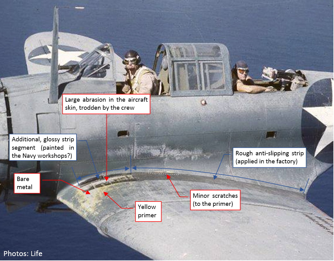
In the photo above, the minor scratches are yellow, because Douglas used a yellow layer of Zinc Chromate primer below the camouflage paint. (The interiors were painted with another layer of the Zinc Chromate, mixed with Lamp Black to obtain a darker, greenish hue).

However, the larger area along the leading edge was often trodden to the bare metal, which you can see in the photo. This scratch has a typical, irregular band of the primer around its borders. In this post I will recreate these abrasions.
The aircraft producer anticipated this kind of damage (at least to some extent), placing a thick, rough, anti-slip strip along the fuselage. It seems to be made of a black, rough material, glued (?) to the aircraft skin (as in the picture above), and spans from the trailing edge to the main spar. However, the most “visited” by the servicemen area in the front of this spar had no such a cover. On some SBDs (including the one on the photo above) you can find a glossy, black continuation of the anti-slip strip. I suppose that it was added in the Navy workshops. It seems to be simply painted using a typical black paint, thus was more prone to the abrasion (as you can see in the photo).

To recreate the effects from this archival photo, I had to paint this glossy black area first. It requires changes in the two textures: color map (because it was black) and reflectivity map (because it was glossy). I created in the source GIMP file separate layers to reproduce these shapes. This way I can simply turn them off while painting another aircraft that did not have this feature (like most of the SBD-5s and -6s). Figure "a", below, shows the color texture image, while figure "b" shows the additional reflectivity map (they share the same GIMP file):

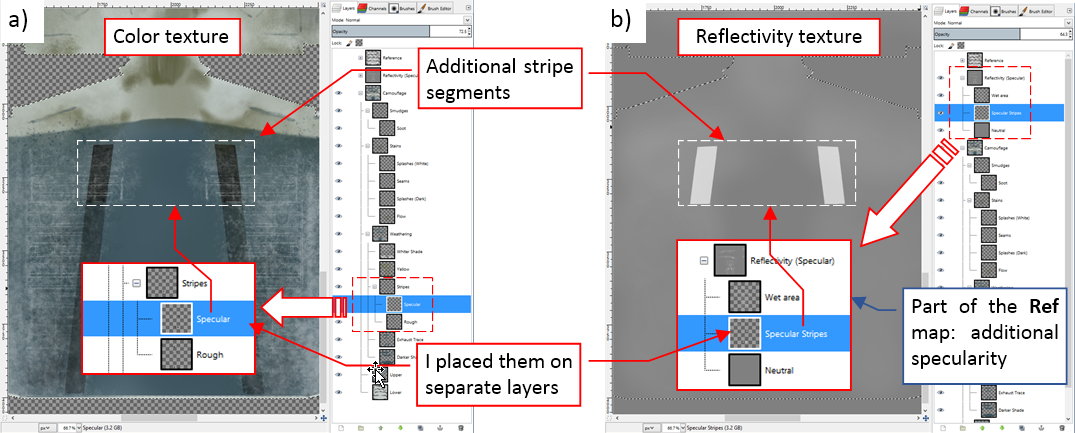
Note that I introduced here another part of the reflectivity texture: the map of the areas that are more specular than other. This is a natural addition to the ref-aux.png map that I used in this post to make the remaining anti-slip strip more rough. There are also some other areas that look more “wet” (specular) than the others. For example – the fuselage sides (because of the small amounts of the oil, spreaded from the engine). I painted them in GIMP in a lighter gray, on a separate layer named Wet area (see Figure "b", above). I saved this image to a file named ref-aux-spec.jpg. However, I could not simple merge it with the ref-aux.png map, because it uses the different UV layout (UVTech). Thus I had to join these images in Blender, using special node that mixes two grayscale pictures (as in Figure "a", below):

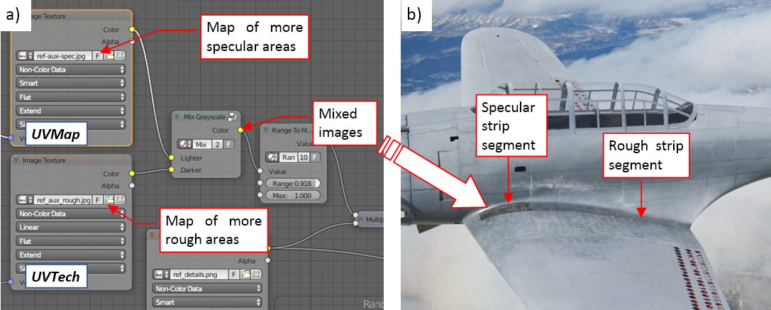
For the brevity I renamed the ref-aux.png file to ref-aux-rough.png. Figure "b", above, shows these updated textures on the rendered picture. Frankly speaking, the weak increase in the specularity of the fuselage sides is not visible here, but you can see the much more accented difference between the reflectivity of the forward and the rear anti-slip strip segments.

I am going to recreate the scratches that you can see in the archival photo using so-called shader mask. Thus, in addition to the weathered camouflage shader that I used so far, I need a “bare metal” shader, which looks like a rough duralumin skin. Figure below shows such a thing:

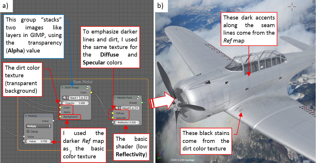
Note that this shader uses the ref_details.png image (see Figure 73-4 in this post) as the base color texture (for the Diffuse as well as the Specular colors). The dark lines from this image create appropriate shadows along the seam lines. I just made this input image somewhat darker (using a Multiple node), to transform the semi-white background color of the original ref_details.png image into metallic gray. What’s surprising, it’s better to use a fixed Reflectivity for such rough (low-reflectivity) metallic shaders. When I tried to use the same ref_details.png image as the reflectivity map for this case, it made the panel seams lighter, reverting the effects of the color texture.

To share the dirt between the “bare metal” and the camouflage shaders, I separated it from the color texture. I named the two resulting images as color-camo.jpg (the weathered camouflage) and color-dirt.png (the soot traces and some stains on transparent background). I used the Stack Image nodes (see Figure "a", above) to combine them with corresponding backgrounds, like the layers in GIMP. Figure below shows these two components of the color texture image:

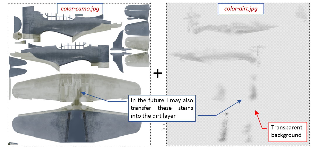
In the color-dirt.png image I initially grouped only the soot traces. It is possible that I will also transfer other layers there. (We will see if I have to do this during the work on the pre-war “natural finish” painting scheme of the SBD-1).

Then I prepared a B/W “shader mask”, painting white, feathered scratches on a black background:

As you can see in Figure "a", above, I decreased the opacity of these shader mask layers while painting, using as the reference the camouflage from the layers below. I also used a copy of the reference image (layer Rivets and seams) to precisely recreate technical details visible inside this scratch. (SBD had flush rivets on this area. Usually the paint remains on their heads even when there is bare metal around). Figure "b", above, shows the final material mask. I saved it to a file named mask-scratches.jpg.

Below you can see how I used this mask in the material scheme:

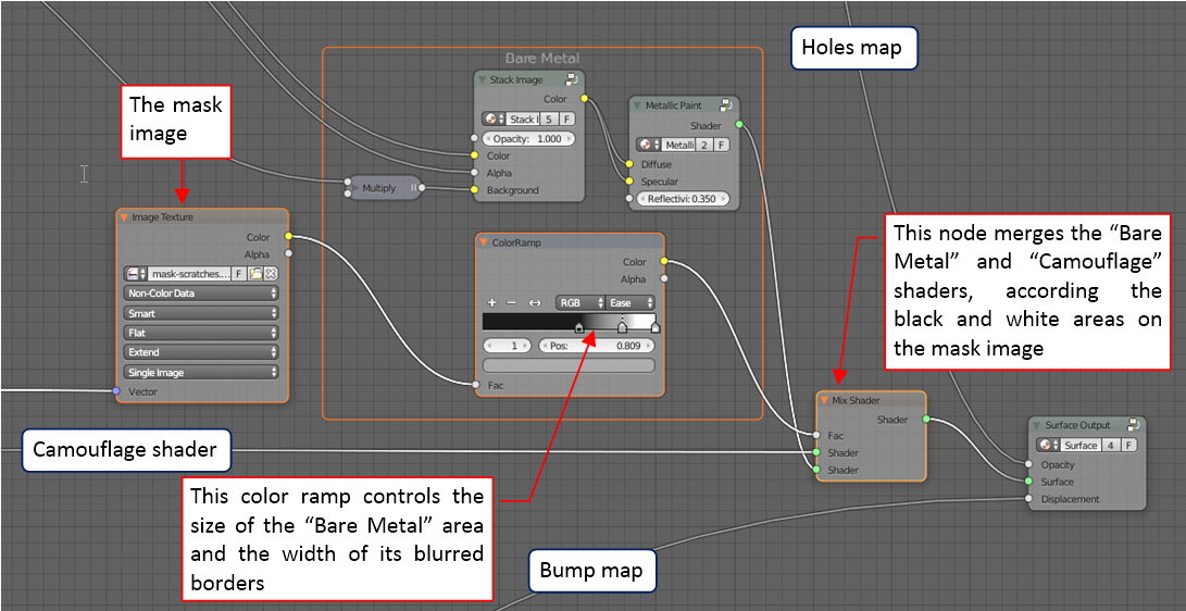
Note that I placed a Color Ramp strip between the mask and the Mix Shader node. The pattern, set in this node, controls the ultimate size of the scratches, and the width of the transition area. (The transition area is “feathered” border of these bare metal scratches, where the share of both shaders is greater than 0). For example, if I want to get the “chips” effect (bare metal areas with sharp borders) I should switch this color ramp mode from Ease to Constant. (It creates a strip that contains just sharp black and white spans, without any “gray transition” between them).

The result of this shader mask looks like the test render below:

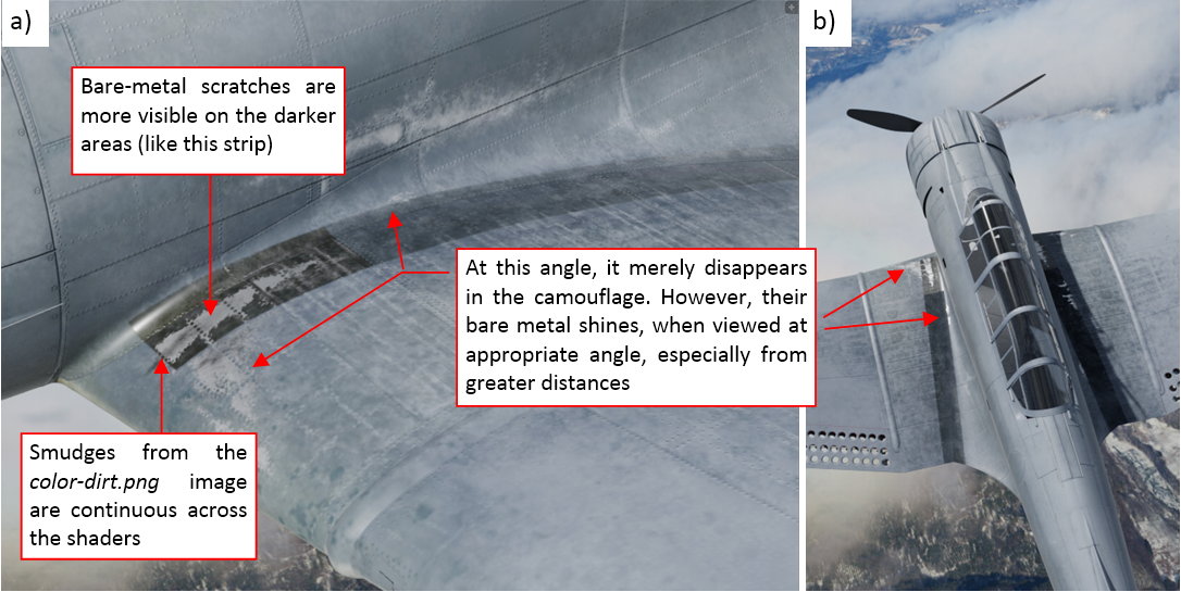
The bare metal scratches look good on the dark background (like the anti-slip strip). For certain viewing angles they disappear in the camouflage, because of their gray color (as in Figure "a", above). Still, they can shine (as in Figure "B", above) when you view them from other sides, especially when you do it from greater distances. (This shining effect looks quite convincing – this is the advantage of this method over scratches painted directly on the color texture).

Now, let’s add the primer to these abrasions! This means that we have to add yet another shader to our material scheme. It is similar to the camouflage shader, with one exception: it has to have a uniform yellow color, instead of the camouflage texture. To reuse all the other settings, I decided to “extract” the final Gloss Paint shader from the X.Textured Skin group. Figure below shows the modified material scheme:

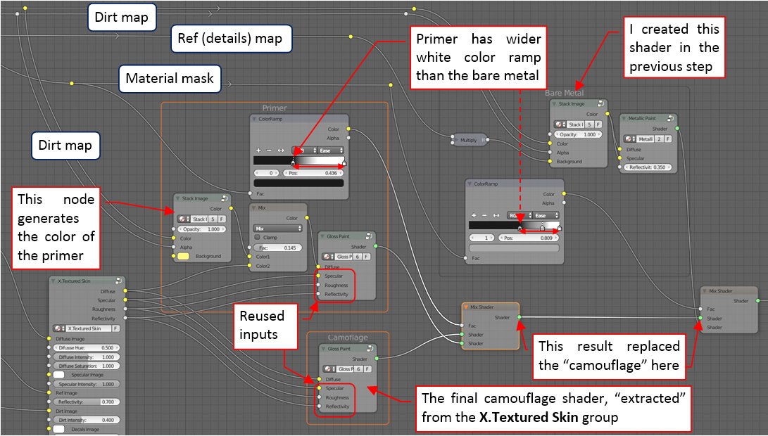
I “cascaded” the camouflage, primer and bare metal shaders, using two Mix Shader nodes. In general, each Mix Shader could use a different mask image. In this case both use the same input mask, but each one modifies it in a different way, using its Color Ramp node.

You can see the result below:

I think that it looks good enough. These and other details bring the final effect closer to the original photo from the beginning of this post (compare the picture below with the first picture in this post):

Of course, there are still differences. (For example - I have impression, that I should use stronger sunlight in my scene, to obtain such a high contrast between the lighter and darker areas as in the original photo). Well, I will work on these issues later.

Using the shader setup presenting in this post, painting all other scratches is a breeze: you just have to add another white splash on the shader mask image.

In the next post I will prepare the “decals” texture, containing national insignia, tactical numbers, and some service labels. (I will add more of these labels during the detailing phase, when I review each area of the aircraft skin).

In this source *.blend file you can evaluate yourself the current version of the model, and here is the GIMP source file of its textures. Because of the large size of the original GIMP file (*.xcf), this post is accompanied by its smaller version (2048x2048px), packed into *.zip file. I think that such a version is sufficient for checking all the details of this image (the structure of its layers, their opacities and mixing functions). The resulting textures (4096x4096) are packed into accompanying Blender file.

  • Member since
    January 2015
Posted by PFJN on Saturday, July 1, 2017 11:40 PM

Hi,

I've literally run out of things to say about your work.  What you have (are) doing is amazing.  Thanks for the detailed posts.  They make an inrcredible tutorial. Smile

Pat

1st Group BuildSP

  • Member since
    June 2014
Posted by Witold Jaworski on Sunday, June 25, 2017 6:29 AM

In this post I will work on the weathering effects of the color texture, while in the next one I will add scratches and some other remaining details.

The weathering effects that you can observe on the aircraft from WWII era are quite “dramatic”. The paints used in mid-20th century were not as chemically “stable” as the contemporary coats, thus they could change their hues in few months of intense service. The archival color photos below show an extreme case of this effect:


These photos were taken by Frank Sherschel on 14th November 1942, for the “Life” magazine. The SBD-3s depicted on the pictures belonged to VMSB-241 squadron, stationed at Midway in that time. Marines received these aircraft in July 1942, but all of them were already used before - most probably on the U.S. Navy carriers. I think that in November 1942 these SBDs had accumulated about 10-11 months of the war service. I will use them as an extreme case of the weathering. (It is always good idea to recreate such an ultimate case in the texture, because you can always make your model “newer” by decreasing intensities of the weathering layers. On the other hand, you cannot use more than the 100% of their intensities, thus you cannot make your model “older” than you initially painted).

Having historical color photos of several airplanes used by the same squadron, you can easily determine the general pattern of the stains, smudges and scratches. This pattern repeats with some random variations on every aircraft. It seems that such a radial engine like R-1820 emitted a lot of oil – in their exhaust fumes and in the air flowing from the NACA cowling. (Because of the high “oil consumption” of the R-1820 the oil tank in the SBD was quite large). The non-specular paint of the two-color Navy camouflage absorbed this oil mixed with the soot from exhaust fumes, creating characteristic dark traces along the fuselage and the center wing. The crew most often walked on the center wing, thus you can see on its upper surface the lighter traces along dome rivets seams and darker, “trodden” spaces in between. There are also some scratches in the paint. Some of them exposed the yellow primer, while the others reached the bare metal of the aircraft skin. (Thus I assume that the first layer of the Douglas primer had a yellow/orange color).

You can also notice some white splashes on the outer wings (traces of the coral sand from the atoll?), as well as the repainted areas around the tactical numbers. (On a black-and-white photo, it would be extremely difficult to distinguish these repainted areas from the oil/fumes traces).

What is interesting – in spite of the non-specular camouflage of these aircraft, you still can see a specular highlight at the wing root (as in figure "b", above).

The key elements of the weathering effect still depend on the technical details of the aircraft skin: rivets and panel seams, bolt heads, inspection doors. However, their pattern is so random, that I cannot recreate them in the SVG image, as I did in the case of the reflectivity map. Thus we need a reference picture of the skin details for painting the color (diffuse) texture. It has to be mapped in the same UV layout (UVMap) as the color texture. To do this, I composed from the key layers of the SVG drawing an auxiliary image, mapped in the UVTech layout. Then I quickly transformed it into UVMap layout using the Bake feature:

The old Blender Renderer engine is a better tool for such a direct transformation of a single texture than the Cycles Renderer. In the Blender file that accompanies this article, I created a dedicated screen layout for this purpose. It is named Texture Baking. You can find there a simple script that I used to switch the UV layout of all model meshes between UVTech and UVMap. To bake a texture from UVTech to UVMap layout, you have to switch the current rendering engine to Blender Renderer and disable nodes in the B.Skin.Camouflage material. Then assign the image (mapped in the UVTech coordinates) to its single Blender Render texture assigned to B.Skin.Camouflage material, named Image for Baking. When you click the Render:Bake button, it will generate the resulting texture (in the UVMap coordinates) in the Test image, which you can see in the UV/Image Editor. You can use Image:Save As command to save it to an external raster file.

I created such a reference image for each SBD version I have modeled (SBD-1, SBD-3, and SBD-5), and placed all of them in GIMP:


The darker areas in this weathering appear between the rivets seams. I decided that it will be easier to recreate them using one layer of darker camouflage color, overlaid by partially opaque layer that contains the weathering pattern (in white). First I painted in this way the right outer wing:


I used this “sample” for testing if such a pattern looks good in the final image:


I think that it looks acceptable. Thus I started to paint in this way the weathering of the whole upper surface.
I create the basic pattern of the lighter traces along rivet seams in four steps:


First I painted the “overall noise” with an “acrylic brush” tool (figure "a", above). Then I changed the tool shape to “pencil” and draw thin lines along rivet seams (figure "b", above). In the next step I used Eraser to make this pattern more random (figure "c", above). Finally, I filled it again with light touches of an irregular brush, to lighten the overall effect (figure "d", above). (This last step is optional, depends how this fragment looks like on the reference picture).

Figure below shows the resulting weathering pattern on the fuselage:


As you can see, it differs from the pattern on the center wing. The lighter traces along rivet seams are thinner, the color is more uniform. Using a separate layer, I added a yellow tint to the darker areas.

Unfortunately, in Frank Sherschel’s collection there is only one, small photo which shows the bottom surfaces of an SBD from this squadron:


You can identify there some smudges on the outer wing and rear fuselage. However, you cannot determine the dirt pattern for the center wing and the engine cowling. (You can only say that they are dirty).

Well, in this case I had to use another, black and white photo as the reference. This photo shows clearly the center wing section of a typical aircraft:


As you can see, I recreated in my image the exact copy of the smudges from this SBD-4 center wing. They are placed on another layer (Flow) in the Stains layer group.

Finally, I enriched this basic dirt pattern with all the additional details visible on the reference photos: white “burnouts” on the fuselage sides, discrete traces of soot. There are also irregular, darker lines along some of the panel seams:


Each of these elements has its own color and layer. Note that the darker lines along panel seams extend across the upper and lower surfaces. I painted them using the same color, but on the bottom surfaces they are more transparent, to obtain the appropriate contrast. (Painting them, I used a 50% opaque mask for the bottom surfaces).

Figure below shows this “weathered” diffuse texture on the model:


Frankly speaking, I am still not satisfied with these results. This weathering requires some minor adjustments. For example: on the reference photos it has a slightly different hue. The fuselage below the tailplane also requires some fixes.

While painting all these weathering effects, I came to conclusion that I cannot re-use them without any modification in the three-color camouflage, used in the SBD-5s and -6s. Thus I will not split the color texture into three interchangeable parts, as I announced in my previous post. I will have to prepare few alternate color textures instead:

  • A colorful pre-war painting scheme (orange wings!), without weathering for the brand-new SBD-1s from the Marines squadrons (+ eventually the later single Light Gray color scheme, as visible in color photos preserved in the Smithsonian Air And Space Museum);
  • Two-color Navy scheme for the SBD-2,-3 and -4s (described in this post);
  • Three-color semi-gloss Navy scheme for SBD-5s and -6s (+ eventually the white variation of this for the SBD-5 and -6 scheme, using on the Atlantic areas);


Of course, I will reuse fragments of the weathering pattern described here in the three-color scheme for the SBD-5s and -6s. However, before I do it, I have to finish this color texture. Thus in the next post I will fix the minor flaws described above, and recreate the scratches visible on the reference photos. Then I will apply the “decals” – national insignia, tactical numbers, etc.

In this source *.blend file you can evaluate yourself the current version of the model, here is the GIMP source file of its textures. Because of the large size of the original GIMP file (*.xcf), this post is accompanied by its smaller version (2048x2048px), packed into *.zip file. I think that such a version is sufficient for checking all the details of this image (the structure of its layers, their opacities and mixing functions). The resulting textures (4096x4096) are packed into accompanying Blender file.

  • Member since
    June 2014
Posted by Witold Jaworski on Sunday, June 25, 2017 6:26 AM

Pat, bvallot, thank you very much for following!

In fact, I post to this thread to demonstrate another approach to modeling. It is always refreshing to look at our common goal (recreating of a historical aircraft/ship/tank/etc) from a different perspective. Sometimes it is easier (for example - I do not have to struggle with the polistyrene properties, as in your 1:48), sometmes it is harder (I had to create the model from scratch, and my "material" - subdivision surfaces - also have their quirks). Personaly, I think that it gives us more freedom of choice about the aircraft we make, and more responsibility about its shape and details. Of course, the computer models can be used as "better, 3D scale plans" for making better scale models. Most probably within a few years the advances in inexpensive 3D printers bring these two modeling branches even closer to each other.

  • Member since
    June 2013
Posted by bvallot on Tuesday, June 13, 2017 1:34 PM

Witold, I've been very consumed by work and family over the last year, but I haven't missed a single post here. The depth and level of detail is quite inspiring. I'll certainly be bookmarking this page to follow up on when I attempt another Dauntless. 1:48 is sort of my wheel house. I felt pretty good about my first attempt, but I did have a few issues here and there that can't really be seen but it leaves me a feeling that I need to redeem myself. I still have to correct the dive brakes. The rods that attach to the flaps aren't all connecting due to the way I constructed the flaps with styrene...the plastic bows and causes the rods to pop off where they insert. It's always something, huh!?

Your build has given me plenty to think about and offered a few extra references that I hadn't previously had. I haven't seen a lot of chatter on this thread but I do want you to realize what you're contributing to the FS community. =] It's very much appreciated.

Keep at it!!

On the bench:  

Tamiya F4U-1  Kenneth Walsh


  • Member since
    January 2015
Posted by PFJN on Saturday, June 10, 2017 6:20 PM

Hi, 

Thanks for the detailed post(s).  They are very informative, and your build/modeling continues to amaze me.

Pat

1st Group BuildSP

  • Member since
    June 2014
Posted by Witold Jaworski on Saturday, June 10, 2017 4:08 PM

Pat, Mike - thank you for reading!

Today I will report my work on the color map. As you will see, the lighter bottom side of the standard Navy camouflage forced me to alter some elements of the reflectivity map presented in my previous post...
____________________________________________________________________

The color (also known as “diffuse”) map is the most obvious texture, which you can find on every game model. In my models it is composed of three separate images: the camouflage, the dirt (stains, soot, etc.), and the markings (national insignia, tactical numbers, warning labels, and all other similar stuff). In this post I will compose the basic camouflage texture.

Some time ago I unwrapped the left side of this model (see this post, Figure 62-3). Now I had to complete this work, creating remaining elements of the right side, and unwrapping them on the UVMap layout. The final result looks like the model in the figure below:

For the precise mapping, I used here the color grid image, which I already used in my previous posts. Note the different square colors on the left and right wing, as well as the different letters on the right and the left tailplane.

The complete UVMap layout looks like in the figure below:

In this layout the areas occupied by each mesh are smaller than in the alternative UVTech map. However, while in the UVTech layout both wings and the tailplane are represented by their left sides, in the UVMap layout each of them has a separate place. However, some elements are intentionally placed over another. For example – the inner walls of the “letterbox” wing slats. In this layout I unwrapped their upper faces over the wing upper surface, while the remaining faces partially “touch” the wing lower surface. (In this way I ensured, that the color of these less visible elements will match the surface around them). There are some other elements, placed over the wing or fuselage in this UV layout.

I will paint the camouflage and dirt textures for this model in GIMP. First I imported the UVMap layout from Bleder, and used it as the reference picture:

Note that I have a separate UV layout for each SBD version (although they are similar to each other). All of them are grouped in a layer group named UV. To be more visible, it is applied to the underlying layers in the Multiply mode.

GIMP is a raster image editor (like the popular Adobe Photoshop). This means that at this moment you have to choose the resolution of your all color textures. (You cannot scale it up without losing the image quality, as you can in the case of vector pictures created in the Inkscape). For this model, I decided to paint all textures as 4096x4096px images. (I still remember that I for my P-40 I regretted choosing two times smaller dimensions for my color textures).

Converting the alpha channel of the reference (UV) pictures into the initial selection, I quickly painted the classic two-color Navy camouflage (as used between 1942 and 1943). First I painted the whole model in the light gray (the color of the lower surfaces). I placed this picture on the layer named Lower:

Then I painted the darker, blue-gray upper surfaces. I placed their picture above, on a layer named Upper. For the convenience, I joined both Upper and Lower layers into a group, named Camouflage (see figure above).

I exported the contents of the Camouflage layer to a file named camo.png, and tested it on the Blender model, in the Textured mode (as in figure "a", below):

In this view you should look at the all edges that are mapped as the “borders” of the UV “islands”. In the enlarged view (as in figure "b", above) you can easily see the missing pixels, which are displayed as black spots. I also carefully examined the border of the camouflage colors: there is always a local excess somewhere, which you have to remove in GIMP. I did this check having Blender window on one display, and the GIMP window on another. When I saw an error in Blender, I immediately fixed it in GIMP. When the source picture “accumulated” a few of such fixes, I refreshed its image in Blender. (As long as there are no painting layers in Blender, I still prefer to correct such errors in the GIMP source file).

When the image was verified, I incorporated it into the material scheme:

As you can see, I used an Attribute node to select the proper UV mapping (UVMap). The texture image is connected to the Diffuse slot in the generic shader node group (X.Textured Skin). For the time being I mixed it with the black anti-slip strip, “filtered” (by the Clamp node) from another picture (ref-aux.png, see this post, Figure 73-9). I will use it in this way until I paint this strip on the color image. Note that Blender allows you to mix images that use different UV maps (ref-aux.png texture uses UVTech mapping). It opens interesting possibilities for precise mapping of detailed emblems (as the squadron/personal insignia).

I already checked how the upper blue-gray surface looks like in previous post (see its final renders). Thus now I focused on the lighter, lower surfaces. Most of the things look good In the full sun, so I rendered the shadowed area of the tail (figure "a", below):

Both paints used in this camouflage were non-specular (i.e. they have low reflectivity and high roughness). For such a surface in a shadow, the most visible texture is the color map. In our case (of the X.Textured Skin group), it means the color texture and the “dirt” component from the reflectivity texture. (X.Textured Skin group internally maps pixels from its Dirt slot onto the color texture, using the Multiply operator).

The technical details of the tail (rivets, seam lines, inspection doors) in figure "a", above, are dimmed and hardly visible. It seems that rendering engine has troubles with such scenes, where the harsh light is accompanied by deep shadows. Thinking how to improve this effect, I thought about one of Blender Guru tutorials, about so-called dynamic range (the difference between the darkest and the brightest point in the picture). Blender Guru explained that the problem lies not in the renderer (Cycles), but in the another area: the color management. Following its recommendation, I installed alternative color management tables in my Blender. These tables were prepared by Troy Sobotka. You can download them from the Filmic Blender project site. The setup is simple *– I just had to replace the contents of Blender datafiles\colormanagement directory with the new files, provided by Troy. Although this package was mainly intended for indoor scenes, they still can somewhat improve such an outdoor scene like mine. You can see the result in figure "b", above. The surfaces in the shadows now seems a little bit brighter and more natural. (IMPORTANT: to see it, you need a device which displays true 24-bit colors. For example - it can be an LCD display that uses the IPS technology. The less expensive LCD monitors, like those used in typical laptops, display only 18-bit colors).

When I started preparing references (archival photos) for the next color texture (the “dirt image”), I realized that the actual dirt pattern from my reflectivity map does not match the reality:

Of course, the archival photo on the left reveals a lot of soot streaks and other dirt, which I still have to paint. Nevertheless, the overall pattern visible on the real outer wings significantly differs from the pattern on my model (you can see it in the right picture). There were no soft “traces” along the rivet seams, as I painted on my model. The panel lines were more emphasized (some of them by the thick streaks, but this detail I will paint in the next post).

Actually, the whole dirt on my model comes from the reflectivity texture (ref-details.png image). As you can see in the scheme from my previous post, I connected the inverted content of my ref map to the Dirt slot. (Internally, pixels from this slot are multiplied with the pixels from the Diffuse slot – i.e. from the color map). Following these findings, I modified the source of the ref-details.png image – the Ref-Details layer in Inkscape:

You can find this picture in the Inkscape source file that accompanies this post. I modified it by reducing the opacity of soft traces along rivet seams (the Blur sublayer), while increasing visibility of the panel lines (the Grunge sublayer). The white highlights of the rivets, which look good on the darker upper surfaces, disappear now on the lighter bottom of the wing. Thus I modified this element, adding there an additional clone of the rivets seams. I set its color to into black (using SVG filters), and clipped (using SVG mask feature) to the areas of the bottom wing and lowest parts of the fuselage.

You can see the effects of this new ref/dirt texture in the figure below:

All the technical details are more visible now. The delicate soft treads along the rivet seams still appear in the shadowed areas, but vanish in the harsh light:

In overall, this model seems to be cleaner than it was at the end of the previous post. (It looks like a factory-fresh aircraft). I will work on this issue (by adding more dirt and weathering), and report my progress in two weeks.

In this source *.blend file you can evaluate yourself the current version of the model, and here are the Inkscape and GIMP source files of its textures. Because of the large size of the original GIMP file (*.xcf), this post is accompanied by its smaller version (2048x2048px), packed into *.zip file. I think that such a version is sufficient for checking all the details of this image (the structure of its layers, their opacities and mixing functions). The resulting textures (4096x4096) are packed into accompanying Blender file.

  • Member since
    January 2015
  • From: Tumwater, WA.
Posted by M. Brindos on Thursday, June 1, 2017 12:42 AM

I specialized in texturing and I really must say how freaking phenomenal of a job you have done on this model. This part of your project I can finally connect with. This is amazing!

I can't wait to see more now. Lol

- Mike Brindos "Lost Boy"

  • Member since
    January 2015
Posted by PFJN on Sunday, May 28, 2017 6:46 PM

Wow, I think I'm going to have to print this entire thread out and reread it several times before any of it really sinks in Smile.  Your work is phenomenal.  Thanks for sharing your techniques, and in-process images/updates.

Pat

1st Group BuildSP

  • Member since
    June 2014
Posted by Witold Jaworski on Saturday, May 27, 2017 1:31 PM

Pat, thank you for following this thread!

Today I will add some basic "weathering" to this aircraft:
_______________________________________________________

I already finished the bump map (in the second-last post), so it’s time to introduce another texture: the reflection (ref) map. It alters the basic reflectivity (gloss) assigned to the material. In addition, it also alters the material “roughness”. (In the typical CG materials the roughness and reflectivity are coupled in an inverse proportion). These two parameters are important, when you have to paint an oil streak or a soot streak. Both are black – the difference between them lies in their reflectivity.

The effects of the ref map are most visible inside these areas of the model that actually reflect the light:

Figure above shows two renders of the same model: the upper one was created without any reflectivity map, the lower one uses a basic ref map. (I created this texture around the technical details of the aircraft skin).

Compare the rivets seams in these two pictures, especially in areas (1) and (3). As you can see, ref map “emphasizes” these elements. In the lower picture the rivets and panel seams look more weathered than in the upper picture. The same applies to the bolts (2). In general, I use the reflectivity map to recreate the weathering and dirt that accumulates on the aircraft. Of course, the dirt pattern of this texture has to be tightly coupled with the corresponding pattern on the color map. (I will describe it in the next post).

I composed the basic reflectivity map in Inkscape, using three overlapped pictures. I briefly describe this composition below, on a representative fragment of the texture: the wing tip. (This fragment is small enough to make visible the minor details of this image. You can also examine the source Inkscape file for the further details). The first component of this texture is a blurred image of the basic rivet seams:

It contains clones of three source layers: Rivets: Dome (turned black), Rivets:Flush, and Shadows. To alter the color of the Rivets: Dome layer clone to black, I used an auxiliary SVG filter that contains just a single ColorMatrix component. Similarly, to blur the contents of this Ref-Details:Blur layer, I used another SVG filter, that contains a GaussianBlur component.

The other component of this texture emulates the small, random dirt and scratches that accumulate around all seams. I named it Grunge:

I composed this picture from clones of the Lines, Contours, Bumps:Bolt and Covers layers. Their contents is “dispersed” here using a special SVG filter. (For details of this solution, see “Virtual Airplane” guide, chapter about Inkscape, section about the dirt effect). I used here a new layer Contours, which I have not mentioned in previous posts. It contains just outer outlines of some selected elements (for example – cowling panels), drawn using thicker black line. (Such a line adds additional dirt along their edges).

I placed the dirt image (Ref-Details:Grunge layer) over the blurred panel lines (Ref-Details:Blur layer), and placed on top of them another layer named Ref-Details:Other. It contains clones of the Rivets, Fabric:Stripes, Covers, and Bolts layers. The idea is that this layer “clears the dirt” off the protruding skin elements (that’s why the clone of originally black Rivets:Flush layer is white here). Figure below shows the final composition of the Ref-Details texture:

The basic elements of this image – clones of the source layers – will update automatically, when I change one of the original layers. This feature is important for me, because I often have to introduce small corrections to the model, even during the last, detailing phase of the project. (You never know, when you find a new picture or drawing, which reveals that a particular detail in your aircraft had a different shape). Some of these corrections require corresponding changes in the textures. The automatic update of the three basic textures (two bump maps, and this reflectivity map) is a great help in such a case.

I exported contents of the Ref-Details layer into a file named ref_details.png, and connected it to the material scheme:

Because this Inkscape image re-uses the same components as in the bump maps, the reflectivity texture uses the same UV layout (UVTech). I connected this texture to two sockets: Ref Image and Dirt Image. The max. (i.e. basic) reflectivity is controlled by the Reflectivity parameter, while the contents of the ref texture decreases this value locally, in appropriate areas. The intensity of this effect is controlled by the Range parameter in the auxiliary Range To Max control node. To control the dirt effect I use the Dirt Intensity parameter (there is no need for another Range To Max control node on this line, because the basic Dirt Intensity = 0). (For explanation of the inner details of the X.Textured Skin group, see “Virtual Airplane” guide, chapter “Texturing the Model”, section “Summary”).

The dirt is hardly visible on the metal surface kept in the “natural finish”. (You can see the effect of this reflectivity map on such a surface in the first figure in this post). Om this example I switched the material to the non-specular Navy Blue-Gray color (see figure above). The U.S. Navy and Marines used this color to paint the upper and side surfaces of their aircraft in 1941, 1942 and 1943. This is just the first approximation – a solid color for all surfaces. (I will create the proper color texture in the next post).

Figure below shows the result of applying the reflectivity/dirt map (connected as in figure above) to a low-specular surface:

Still, the aircraft depicted in the figure above seems “too clean”.

To further enhance this dirt pattern, I combined the original image with a random “noise” pattern (see figure "a", below). This random pattern is composed from two different Noise Texture nodes of different size. One of them creates big darker and lighter “clouds”. I set the intensity of the General Noise texture (in the accompanying Range To Max node) so that its darker “clouds” have similar shade to the elements of the of the ref_details.png image. It makes the resulting dirt/ref pattern less regular (see figure "b", below):

The other component of the General Noise pattern creates a “white noise” of small darker and lighter spots (see figure "c", above). It resembles the real micro-dirt, dispersed evenly on the whole aircraft surface.
On all SBDs you can see anti-slip stripes running along both sides of their fuselages. Its surface was painted in the factory with a special “rough” paint. It seems to have much lower light reflection than the rest of the aircraft surface. I will recreate this reduced reflectivity of this strip on the ref texture, while I will paint it in black later, on the color texture.

It seems that the anti-slip strip is longer on the restored aircraft than on the photos of the original SBDs. To determine its true (i.e. original) size and location, I used the archival photos, as well as the contemporary photos of the few SBD wrecks (taken before their reconstruction). Below you can see two of these photos:

Figure "a", above, shows the original state of the SBD-5 restored by the Pacific Aviation Museum, while figure "b", above, shows the SBD-3s on the deck of USS “Enterprise”, on April 4th, 1942. It is a good photo, because it shows multiple aircraft belonging to the same squadron. You can see on these bombers that the anti-slip stripes extend from the trailing edge to the main spar of the wing. Precisely the same span you can see in the original SBD-5 from figure "a", above. However, on some airplanes that I saw on the photos the anti-slip strip is extended over the main spar, into the area that I marked in figure "a" with white outline. I suppose that this forward part of the strip could be painted in black by the local crews. It seems that they used various paints for this purpose, sometimes even the glossy ones.

At this moment I recreated this strip in its standard shape: from the trailing edge to the main spar. For this (and other, similar) purpose I made an auxiliary reflectivity map, and named it ref_aux.png (see figure "a", below):

You can see that I drew the anti-slip stripe in black there – this means that this area will have the minimal reflectivity (and maximum roughness). Thinking about the eventual glossy fragment at the end of this strip, as well as the oil streaks that I will paint in the next post, I set its background color to neutral gray (50% black). All the glossy elements will be lighter than this color. In addition to the strip, I decided to decrease the reflectivity of the fabric-covered control surfaces. (The fabric surface is rougher the metal surface, even when you paint them using the same paint). Because this difference in material reflectivity is not as intensive as on the anti-slip strip, I filled the aileron, elevator and rudder outlines with a dark gray instead of black.

Figure "b", above, shows that I mixed these auxiliary and basic ref maps using a Multiple node. This means, that now the background color of the resulting image is close to the neutral gray (it was 92% white, before). To compensate this difference, I had to increase the basic Reflectivity (the parameter in the X.Textured Skin group) to the maximum.

Below you can see the results of applying this additional ref map:

In figure "a", above, you can clearly see the anti-slip strip as a dark area on the center wing. Similarly, the fabric-covered aileron is also somewhat darker than the rest of the wing tip surface. However, this effect depends on the incoming light angle. When you look at this model from the opposite direction (as in figure "b", above), you will notice that these areas are lighter! In the real world, you can find the same effect on the photos of the aircraft painted with non-specular paints.

Figure "c", above, shows the final effect of the reflectivity maps, created in this post. In fact, this is just a beginning: this texture represents an “overall dirt”, evenly dispersed on the whole aircraft. Now I have to add the soot and oil streaks that appear on every real piston-engine airplane. The radial R-1820 engine (and especially its exhaust stacks) provided plenty of interesting patterns on the SBDs fuselages and center wings. However, I want to paint this dirt simultaneously on the reflectivity map and the color map. Thus in the next post I will prepare the basic color (diffuse) texture, then we will return to the “dirt painting”.

In this source *.blend file you can evaluate yourself the current version of the model, and here is the source Inkscape file of its textures.


  • Member since
    January 2015
Posted by PFJN on Friday, May 19, 2017 8:23 PM

Hi,

Your attention to detail is amazing.  I look forward to seeing how everything turns out.

Pat

1st Group BuildSP

JOIN OUR COMMUNITY!

Our community is FREE to join. To participate you must either login or register for an account.

SEARCH FORUMS
FREE NEWSLETTER
By signing up you may also receive reader surveys and occasional special offers. We do not sell, rent or trade our email lists. View our Privacy Policy.