SEARCH FINESCALE.COM

Enter keywords or a search phrase below:

SBD Dauntless

73381 views
196 replies
1 rating 2 rating 3 rating 4 rating 5 rating
  • Member since
    June 2014
Posted by Witold Jaworski on Tuesday, May 16, 2017 12:47 PM

PFJN - thank you!

_____________________________________________

This post is a small digression about a modeling technique that may be useful for those, who would like to build their own 3D models.

There is a detail on the bottom surfaces of the SBD center wing: an opening, made partially in the cover of the fuselage belly:

0072-01.jpg

The difficult part of this detail is its flange, stamped in the fuselage cover. I just have two photos of this element, both of average resolution. On both of them you can see a typical circular recession, made around the opening in the belly cover. In fact, such a feature is quite common in the sheet metal design (you can see plenty of such stamped flanges in various places inside your car). This is a minor detail, too small for any serious modeling, but too large for recreating it with the textures.

I had an idea of shaping this recession using so-called displacement modifier. (I used it for a certain purposes in my previous model). It displaces mesh faces along given direction, on the distance determined by the color intensity of assigned texture. (That’s why I waited with this detail for the texturing phase). The displacement modifier requires plenty of small mesh faces. I thought that I will generate them by increasing the number of mesh subdivisions in the Subdivision Surface modifier assigned to this cover. Preparing for this, I split the mesh of bottom fuselage in the middle. This operation created two objects, representing the forward and rear part of the Dauntless “bomb bay”. I was going to increase the subdivision level in the rear part, which contains the flange.

However, after initial trials I went to the conclusion that the displacement modifier is not optimal solution for such a circular shape with rounded edges. It would require relatively high subdivision level, to obtain this shape with appropriate precision. (It would generate hundreds thousands of additional elementary faces). Too much troubles for such a small detail. Thus I decided to find another method that requires less resources.

Finally I modeled it using a technique that resembles me methods used by dentists. First I cut out in the belly cover circular area around the flange:

0072-02.jpg

To not complicate the mesh of this cover, I did it dynamically, using additional Boolean modifier and an auxiliary cone (the latter as the “cutting tool”).

Then I formed around the opening a small ring of faces, and extruded them, creating the basic shape of the flange:

0072-03.jpg

In the next step, I trimmed the extent of this mesh faces using the Boolean modifier and the same auxiliary cone that I used for the belly cover. Then I fitted external edges of this flange to the edges of the belly cover:

0072-04.jpg

Note that, thanks to the Boolean modifiers, I only had to fit these edges along the normal direction of the joined surfaces. It required less work. To further facilitate this task, I assigned a contrasting red color to the rim of the belly cover.

Finally I mapped this small detail on the general UV map (figures "a", "b" below):

0072-05.jpg

The UV map of this patch is a simple projection from the vertical view. So far it looks good – there are no visible seams between the patch and the belly cover (figure "c", above).

Figure below shows the final result on the rendered picture:

0072-06.jpg

You cannot recognize here that this fuselage cover is created from two separated objects – it looks like a single one. This is the effect I wanted to achieve.

Of course, this method of using shared Boolean “tool” for trimming both involved objects is useful for modeling single features stamped in a sheet metal. It would require too much work for modeling more than two or three such objects. (Fortunately, they do not occur too often).

You can examine the details of this mesh in this source *.blend file (this the same file that I attached to the previous post).

  • Member since
    January 2015
Posted by PFJN on Saturday, May 6, 2017 1:52 PM

Hi,

Thanks for the update.  Everything looks incredible. Big Smile

Pat

1st Group BuildSP

  • Member since
    June 2014
Posted by Witold Jaworski on Saturday, May 6, 2017 6:13 AM

Although the technical details of aircraft skin are symmetric in general, there are always exceptions. For example, look at the bottom surfaces of the SBD (Figure below shows them on my model):

0071-01.jpg

As you can see, there are several details that are not symmetric. (In addition, let’s do not forget about the asymmetric opening under bottom covers of the fuselage, visible on this picture – see Figure 70‑9 in my previous post).

So far I mapped only the symmetric half of the wing on the UVTech texture layout. It occupies a significant portion of the space. Such a size allowed me to draw all the technical details in higher resolution. The plan was that both wings will be mapped in the same points of the UV space, because most of their structure is symmetric. For the few asymmetric details, I was going to prepare additional areas, intended for the UV mesh faces that contain these elements.

Let’s see how it works in practice. I created the right side of the center wing by mirroring its left side (see figure "a", below). Initially, the texture image is symmetric, because mesh faces from both sides are mapped onto the same areas in the UV space:

0071-02.jpg

Then I drew the asymmetric elements of the center wing on the image, and “flipped” an L-shaped selection of the corresponding UV faces onto this area (figure "b", above). However, when I looked at the effect in the 3D space, I saw a huge texture deformation (figure "c", above). Why did it occurr?

The reason of this deformation is the Subdivision Surface modifier that I used to smooth this mesh (as well as most of the other meshes in this model). To preserve proportions of the texture image, I enabled its Subdivide UVs option. When I turned on in the UV/Image Editor the preview of the modified (ultimate) UV faces, I saw the pattern as in figure "a", below):

0071-03.jpg

Edges of the ultimate, subdivided UV mesh faces are marked in yellow. As you can see, the Subdivide UVs option “smooths” all inner corners of the original UV layout! Well, I cannot disable this option, ibecause it would deform the texture details, on all mesh faces. Still, it is possible to counter this “inner corner” effect by sharping selected seam edges (i.e. by increasing their Crease coefficent to 1.0). As you can see in figure "b", above), I was able to fix most of the original deformation in this way. However, while I could mark as sharp any of the “rib” edges, I could not do the same for the perpendicular “stringer” edge, because it would change the wing shape. (It would alter the side view profile of the center wing).

All in all, the solution for the wings was to “cut out” from their UV layout “stripes” of the faces that span across whole wing chord. Such a stripe has no inner corners (figure "a", below):

0071-04.jpg

As you can see in figure "b", above, it produces the desired effect. The drawback is that it occupies more precious UV space, and I had to replicate more details on this drawing (for the whole span of such a “stripe”).

There are also few differences between the left and the right outer wing:

0071-05.jpg

Strangely enough, aircraft designers usually place all additional stuff like the aileron tab or landing light on the left wing. At this moment I just marked on the wing the contours of these two lights. During the next, “detailing” phase of this project, I will create all of these three details shown in the figure above as separate objects. However, I still have to modify the bump map texture, because of the different rivet pattern around these lights and frame around aileron trim tab. (When there is an element without influence on the rivets/panels pattern, I skip it at this moment. For example: in the left leading edge of the center wing there is small round inlet of the cockpit ventilation air. It does not alter the rivet seams, thus I will recreate it completely during the detailed phase).

Following the experiences with the UV mapping of the center wing, I stripped two full-span bands of the UV faces from the left wing and the right aileron:

0071-06.jpg

Frankly speaking, drawing details of these additional strips in a way that they seamlessly fit the rest of the wing was quite difficult. As you can see, I also made small adjustment on the leading edge seam, on both wings. (It removed the deformation described some time ago in this post, Figure 64-9).

The UV layout depicted above contains three inner corners, all located on the leading edge. This is a kind of a compromise: I used sharp “rib” edges (Crease = 1.0) to minimize the overall deformation of the mesh UV faces around these points. They still bend the texture along their “stringer” edges (as in the case of the center wing, depicted previously in this post). However, in these two particular cases I managed to “hide” this unwanted effect. Figures below show how I did such a thing:

0071-07.jpg

Figure "a", above, shows the fragment around the landing attitude light indicator and its faces in the UV space. This is a simple quad, without inner corners. As you can see, I mapped the inner wing edge as a straight line, to facilitate drawing of the multiple rivets and panel seams that run along it. Figure "b", above, shows the details of the corresponding inner corner in the main part of the mesh. I used a sharp “rib” edge along this seam. Still there is deformation along the perpendicular “stringer” seams, but it is practically invisible. There are two factors that “hide” it:

  1. The edges adjacent to the seam edge are relatively close to each other, which minimizes the deformation size;
  2. The seam edge runs in “safe” distance between nearest visible element of the texture image (a rivet seam), so the deformation in the UV mapping disappears before it reaches this image;


The possibility to “cut out” such a small part from the main body of the UV faces preserved precious UV space. It also allowed me to avoid duplicating on the texture picture of all the details along the inner edge of the left wing. (It would require a few hours, to fit such a separate fragment to the rest of the picture).

Apart the differences on the bottom of the fuselage, depicted in the first figure of this post, there are also differences between its left and right side:

0071-08.jpg

The circular door of the life raft compartment was located on the port side (you can see it in the last picture from the previous post - Figure 70‑10). The raft was packed in a tube riveted to the starboard skin, creating characteristic circular rivet pattern (visible in the figure above). The door to the baggage compartment was also located on the starboard. There were also differences in the locations of the steps to pilot’s cockpit.

The shape of this fuselage is much more complex than the wing. I cannot mark any of its edges as sharp, because it would change the shape of this element. Thus, after the experiences with the wing, I decided that I need to map in the UV space the whole fuselage right side. Fortunately, I preserved some spare space on the original UVTech layout. Now I used it to fit this part:

0071-09.jpg

On the picture above, I marked the newly added objects in orange. The main dilemma was how to fit another fuselage silhouette by replacing as few drawing elements as possible. As you can see, I finally decided to “shuffle” the cowling panels from the left side of the original image into the spare area. It created enough space for the fuselage on the left. Note that I also added the right sides of the cowling panels (because they also were asymmetric: there were two inspection doors on the left side of the cowling).

Figure below shows the source image of the bump textures adapted to this new layout:

0071-10.jpg

My experience tells me that in the future I will have to update some details of this picture, following new findings in the photo material (it is just a matter of time). Avoiding applying the same modification twice, I decided to join into a group all the originally drawn elements that are identical for both sides of the fuselage and belong to the same layer. Then I created a mirrored clone of such a group and placed it over the right side of the fuselage. After I “filled” this contour with all the required clones, I drew the asymmetric details. In the future, when I change contents of any of these groups on the fuselage port side, they will be automatically updated on the starboard.

I drew the other side of the elevator in the same way. In this case, the whole difference is a plate mounted between two ribs. It contains the hole for the trim tab actuator. Of course, I could “cut out” this very mesh fragment, as I did in the case of the aileron. However, in the SBD the elevator is smaller than the aileron, thus I decided to make the “full size” copy of its opposite side. (Just to make the eventual future modifications easier).

In this source *.blend file you can evaluate yourself the current version of the model, and here is the source Inkscape file of its textures.

  • Member since
    June 2014
Posted by Witold Jaworski on Saturday, April 22, 2017 1:48 PM

In the middle of April I described the enhanced the bump map texture effect, using two different images. This is the continuation on this subject.

Have you ever noticed that the classic stressed skin of a real aircraft is not ideally smooth? It is more visible in the areas where the skin is thinner, especially on an old, “weary” aircraft:

0070-01.jpg

The wing on the left (see the picture above) belongs to a SBD-4 (BuNo 10518) from Yanks Air Museum in Chino. This wing was recovered separately from Guadalcanal (circa 1980), and restored a few years later. This aircraft is in flyable condition (registered as N4864J), but has not flown since its restoration.

The wing on the right on the picture above belongs to a SBD-5 (BuNo 28536) from Planes of Fame, also in Chino. This wing was also recovered from Guadalcanal, in the same time as for BuNo 10518. This aircraft was restored, registered as N670AM, and made its first flight in 1987. Since that time it has been flying during various air shows.

I assume that the skin of the SBDs that were flying in 1940-44 resembled the skin of the wing from the left picture. Note that the leading edge and the central panels have no visible deformation. (However, their skin still could deform a little in the flight). This is because they were created from relatively thick (0.032”) sheet metal. The buckling of the skin is more visible on the panel behind the rear spar, because it was made from a thinner (0.025”) sheet.

It is quite easy to obtain this effect using textures:

0070-02.jpg

To do it, I re-used the contents of the Rivets layers from the source Inkscape image. However, before I did it, I drew additional, thick gray lines below the rivet seams. I placed these lines on a separate layer, named Shadows:

0070-03.jpg

Once this was done, I could compose the final texture image using these lines and clones of the Rivets sublayers:

0070-04.jpg

First I altered the color of the white Rivets: Dome elements, using a simple SVG filter that blackens everything. Then I blurred this composition, using another SVG filter: cascading Gaussian blur. (For details of this solution, see “Virtual Airplane” guide, chapter about Inkscape, section titled “Using filters”).

Finally, to decrease the influence of this texture on the forward part of the wing, I covered it with a gradient-filled shape:

0070-05.jpg


As you have noticed, in this composition I re-used contents of the Rivets layers, using their clones. Using such clones in the final texture image allows me to easily modify contents of these pictures in the future. When you alter any element in the source layer, Inkscape immediately updates all its clones. Thus I rearranged the structure of the SVG file (see the layers pane in Figure 70‑5). I grouped all the source layers (Rivets, Panels, Covers, Bolts, etc.) into a layer group named Source. Then I created another layer group, named Result. Each of its sublayers contains the composition of one final texture image (Holes, Nor-Details, Nor-Blur). Their contents is composed from clones of the Source sublayers, with altered opacity and (sometimes) applied various SVG filters. (See the source Inkscape file).

When I work on such a drawing, I am drawing new elements (or modifying existing ones) on the Source sublayers. Then from time to time I export the final images generated by the Result sublayers to the raster files, used by Blender (holes.png, nor_details.png, nor_blur.png).

In the process of creating textures, the most troublesome areas are those along seams, especially when such a seam contains a corner. Some time ago I tried to avoid breaking the skin panel edge along such a UV seam (see this posts, Figure 67‑3). Now I can see that this was a bad idea:

0070-06.jpg

The rivets in the line that runs along the UV seam are skewed. They also have different sizes. All of this has occurred because of the high shape distortion of the bottom faces that belong to the large wing fillet.

I placed the small part of the fuselage inside the UV seam at the center wing. This fragment is undistorted. The remaining triangle (marked in orange in the figure below) is an area where the mesh faces mapped onto UV surface have high distortion (see figure "a" below):

0070-07.jpg

After some deliberations, I decided that it is much easier to join the few rivet lines that run across an UV seam, than to improve these skewed rivets produced by the current UV mapping. (Well, as you can see, the “improvement” of the seam line that I made some time ago was a bad idea). Thus I had to shift the UV seams to the outer edges (see figure "b", above), and “glue” some additional mesh faces to the center wing. This time I took care to minimize deformation of the faces that remained outside the mesh seam.

Figure "a" below shows, that I was able to precisely match the rivet lines across this new seam. It was not as difficult as I thought. Figure "b" below shows the UV map of this area and the original image of the panel seams and rivet lines:

0070-08.jpg

Note that this time only small number of rivets occur in the highly deformed area. On the other hand, because the degree of deformation is lower than in the previous case, these rivets are not ideal, but look “acceptable”, at least.

Figure below shows both bump map images, that I mix to obtain the texture of the technical details:

0070-09.jpg

At this moment, I filled with appropriate details all the common surfaces, and the elements belonging to the SBD-3. As you can also see, I already drew some asymmetric elements on these textures. However, before I map them, I have to apply the Mirror modifiers to the appropriate meshes of my model. I will do in the next post. (I delayed this operation as long as I could, because presence of the Mirror modifiers allowed me easily alternate the model shape. (I had to modify its left side only. Blender took care on updating of the right side). However, after so many months of various checks I can only hope that the shape of this model “seasoned” enough, so I will not have to modify it in the future).

Figure below shows my model. (To make the effect of the bump textures more visible, I significantly increased their intensity):

0070-10.jpg

Strangely enough, I obtained such an intensity increase by setting control nodes of these two textures to negative values: Moderate:Range = -1 (nor_blur.png) and Range From Min:Min = -3 (nor_details.png).

Actually, the textures of this model are symmetric, which means that there are many missing/wrong details on the fuselage right side. In the next post I will introduce asymmetry to these meshes.

In this source *.blend file you can evaluate yourself the current version of the model, and here is the source Inkscape file of its textures.

  • Member since
    June 2014
Posted by Witold Jaworski on Saturday, April 22, 2017 1:47 PM

Pat, thank you for following this thread!

I have seen that other 3D modelers do their stuff much quicker than me. I am relatively slow, so maybe it does not require as much time as you estimate to make a decent computer model :).

  • Member since
    January 2015
Posted by PFJN on Sunday, April 9, 2017 7:46 PM

Hi,

Thanks for all the detalied posts.  I always wanted to try and do a detailed 3D model, but I'm not sure that I'd ever have the time to devote to it, like it looks like you did.

Most my 3D stuff is ship related abd has been very simple, but its all still fun.

Can't wait to see the rest of your info.

Pat

1st Group BuildSP

  • Member since
    June 2014
Posted by Witold Jaworski on Saturday, April 8, 2017 12:55 PM

Originally I was going to describe the finished bump map in this post. However, when I started writing it, I discovered that I have enough materials for at least two subsequent posts. Thus I decided to split this text into this and the next article.

There are many small openings in the aircraft skin. For example – perforation of the SBD Dauntless wing flaps, or small slots for control surfaces actuators. It would require a lot work to model each of such details “in the mesh”. What’s more – it would make the model meshes much more complex, which would hinder the UV mapping, and so on.

Fortunately, there is a much simpler solution for all these small openings. Just draw their shapes as black objects on white background, then use this picture as so-called opacity map:

0069-01.jpg

As you can see in figure above, the final result does not differ from the openings modeled “in the mesh”.

For this opacity map I used a 4096x4096px image, mapped with the same UV coordinates as the bump map (i.e. UVTech coordinates). Below you can see how it is connected to the material scheme:

0069-02.jpg

I also used these black contours in the bump map (they create impression of “metal sheet thickness” around edges of these openings).
Of course, if you wish to make extreme close-ups of the model, you can generate from the source Inkscape drawing a raster picture of higher resolution (8192x8192px?). In the extreme cases you can even create a separate UV map for the opacity texture, enlarging the areas around holes and reducing all the others. (I do not need such an extremal solution in this model).

Working on this model, I am drawing the bump map and the opacity map in parallel.

In the previous post I showed how I recreated bump map details of a classic stressed skin: rivets, panel edges. However, the fabric-covered surfaces, like the aileron, require different elements:

0069-03.jpg

As you can see, the background color of this image is darker than in the previous post (it is 75% black). I decided to use it, because most of the elements on the SBD skin is protruding (rivets, inspection doors). To recreate the protruding rib edges, I used a combination of linear and circular gradients (the latter for the circular endings of each rib). These gradients have a sharp, symmetric, parabolic profile. (For details of this solution, see “Virtual Airplane” guide, chapter about Inkscape, section titled “Mapping the fabric-covered surfaces”).

I also used gradients to recreate flanges, stamped around the flap holes:

0069-04.jpg

I set the opacity values in the subsequent nodes of this gradient so that they match the profile of this flange.

For another element I had to use a different solution. The fabric between ribs is tensed like a membrane, so in an aircraft standing on the ground it is flat. However, in the flight it is deformed by the airflow. To reproduce this deformation, I added another shape to the bump map:

0069-05.jpg

First I sketched black shapes in the areas between ribs. Then I used a special so-called SVG filter to blur these areas. (SVG filters are “dynamic” modifiers: I still can turn it off to modify the original contour). Such a blurred shape creates gentle recesses on the rendering.

One note about implementation of these recesses in the bump maps textures. To obtain the effects depicted above I had to intensify the “black” components. The contrast between black areas and 75% black of the background is relatively low in the basic texture (see the fragment of nor_details.png image, presented below). To make these recesses deeper, I had to add another texture (nor_blur.png – see figure below):

0069-06.jpg

Pixels from both images are merged in the material schema using Multiply node, thus all black areas in the result image are still black. Before the Multiply node, each texture has its own control node. These nodes control influences of their sources in the resulting bump map image (i.e. in the input delivered to the Displacement slot in the surface output node). The simpler Moderate node can make nor_blur.png darker, while the control node of nor_details.png makes it lighter (the Min value), but simultaneously it can “flatten” its grayscale Range. Comparing to altering the shades of the source image layers in Inkscape such a solution has two advantages:

  1. You can easier to alter their intensity in the material schema, and you can instantly see the effect on the rendered picture;
  2. Blender converts output from Image nodes to floating-point numbers, thus you will not lose any contrast from the source image. (In Inkscape every elementary color component is converted to a byte integer 0..255, thus when you decrease color intensity range, it can lose some of the image contrasts);


Of course, I can also decrease depth/height of a single element (for example – recesses of the fabric surface between the ribs) by reducing its opacity in Inkscape. However, to apply such a change, you have to export the new version of the texture image from Inkscape and refresh it in Blender. It requires more “clicks” than altering of a single slide in the material scheme. On the other hand, I did not want to use too many images in the material schema. Thus I decided that I will use two source bump maps in Blender. I expect that I will alter their intensities more often than the others.

Figure below shows the updates that I made in this post, on the model:

0069-07.jpg

As I mentioned before, the rivets and panels seams created by the bump maps are visible from a relatively narrow field of view. The camera used to create the picture above was outside this area. They will become more visible when I apply other textures (reflectivity map, color map).

In this source *.blend file you can evaluate yourself the current version of the model. Note, that the enclosed texture images covers just the wing (BTW: it had a hell of inspection doors on its lower surface!). There is no image for the tailplane, nor for the fuselage, yet. I will finish these areas and describe in the next post, which will appear in two weeks.

  • Member since
    June 2014
Posted by Witold Jaworski on Sunday, March 26, 2017 9:36 AM

OK, I completed in March my "daily" project, so I am back at my work here.

In this and the next post I will describe my work on the first of the textures required for the SBD Dauntless model. It is called bump (height) map. I use it for recreating all of the minor details that are visible on the aircraft skin.

However, before I begin this work, I had to put my model into more “natural” surroundings. I imported the environment (World) and the material settings from my previous model (the P-40). You can see the initial results below:


Of course, the propeller of this aircraft is static, and there is nothing in the cockpit and under the engine cowling. Do not worry, this is just the first approximation! The principle is that you should work with the materials in the final environment. Otherwise the final result may not look as you want. In this case there is an outdoor scene, full of the sunlight. (Every painter will tell you, that everything on the picture depends on the light: many details would look quite different in the indoor lights and their soft shadows).
As you can see, I decided to start this work with an ideal, smooth and shiny material. Each new texture that I will apply will make it more realistic.

Note for those, who will examine the contents of the Blender file that accompanies this post: I am using the Cycles renderer to create this one and the future pictures. (Cycles is one of the Blender rendering engines). The node-based schemas of its environment and materials are quite complex. What’s more, I modified them after importing from my P-40 model, temporarily removing all of the original P-40 textures, and disconnecting many fragments that initially are not needed:


If you would like to analyze details of this setup – you can find its step-by-step description in vol. III of the “Virtual Airplane” guide. It shows how to obtain the required effects, and also discusses some of the possible alternatives.

Creation of the bump map resembles work on a new scale plan. I am drawing it as the scalable (vector) drawing in Inkscape, adding new details to the picture that I started in one of the previous posts. Keeping the source picture of this texture in the SVG format allows me to quickly generate image of any resolution.

I decided that it will be much easier to use the same texture for all of the SBD versions. Thus I had to shift the UV maps of some version-specific elements (mainly the engine cowlings) into the other, unused areas of this UV space.


Then I had to fill the areas between the panel lines with rivet seams, bolts and various inspection doors. I stared with the center wing area. I used the reference drawings (scale plans and the UV mesh layouts) to create the first approximation of these lines:


Technically, I sketched the rivet seams as dotted lines, using a customized dot pattern. (You can find how to do it in the “Virtual Airplane” guide, in the chapter about Inkscape, section titled “Drawing a dotted line (rivets)”).

Then I matched these seams against the reference photo. Initially these rivets were in red, because this color makes them more visible against the background picture:


During this work I had both: Blender and Inkscape windows on my screen, side-by-side. On the reference photo in Blender I could see the differences between the real rivet seams and my drawing. Using these findings, I updated accordingly the drawing in Inkscape. Then I exported it from Inkscape as a new version of the *.png file, reloaded it in Blender, and looked for the remaining differences. Refreshing the mapped image with these “export+reload” commands is quick and requires just two mouse clicks, and one keyboard shortcut in Blender. Usually I need between 3 and 6 of such iterations to obtain a satisfactory match between my drawing and the photo of the given part of the aircraft.

When the rivet seams are in place, it is good idea to check if the internal ribs and spars fit their lines. (While working on the wing, I created a few of these internal reinforcements inside the wheel bay *– see figure below):


In the 3D View mode Blender draws the texture on both sides of the surface, so such a comparison is pretty straightforward. To see the rivet seams “through” the elements being verified, I switched their display mode to Wire. When I identified a difference, the rule was that the rivet seams are in proper location (because they were already verified against the reference photos, while these ribs and spars were based just on the reference drawing). In the case depicted above, I had to move forward the front spar (by less than 0.5”).

When I verified all the rivet seams from the current area, I switched their colors. Because the leading edge of the SBD wing had smooth finish with flush rivets, I created for them new sublayer, named Flush. These seam lines are black. The remaining rivets had classic (dome) heads, thus they are white. I placed them on another sublayer named Dome. I also added to this drawing the inspection doors and the fuel filler cover:


In the bump map texture, the shade of the gray determines the height of an area. The highest element is white, while the lowest is black. Thus I switched the background color of my Inkscape drawing to the neutral gray (50% black + 50% white). Then I could recreate the aircraft skin panels. In the SBD Dauntless these panels overlapped each other. To achieve this effect, I used areas filled with linear gradient:


In this fragment of the aircraft skin I used only areas filled with vertical gradients. I placed them on Panels:Vertical sublayer. (In more general cases, I will also use another set of panels, from :Horizontal sublayer). There are always some sheets riveted atop other panels. In this drawing, I drawn them as the lightest areas, placed on Overlays layer. To decrease variation of the rivets height between the darker and lighter areas, I made their layers partially transparent. (See more details of this method in the “Virtual Airplane” guide, in the chapter about Inkscape, section titled “Mapping construction details of airplane surfaces”).

As you can see in the figure above, I also sketched various minor openings in the aircraft skin. Initially they are red (just for easier matching against the reference photos). Ultimately the verified elements from this layer are black. I will use them not only for the bump map, but also for another auxiliary texture: the opacity map (you will see it “in action”, soon).

OK, let’s check how this first fragment of the bump map looks on the model. I exported it from Inkscape as a raster image (4096x4096px) named nor_details.png. Then I added to the material schema an Image Texture node, which represents this image. It is connected to the Displacement slot in the material output:


As you can see in the figure above, I selected one of the available UV maps by name *– using the Attribute node. Usually in my schemes it is accompanied by a UV Fallback node. This custom (group) node provides the default UV map for the meshes that do not have the UV map specified in the Attribute node.

You can evaluate the results below:


The first thing that I noticed: the dark gray dots that I used to emulate the flush rivets should create less visible seams. Currently their rivets seems too deep – so I should make these dots lighter. The same applies to the small bumps around bolt heads (visible on the covers).

You can see the details created by the bump texture when you place the model between the camera and the sunlight. (Check it, playing with the rendered model that accompanies this post). These skin details can completely disappear, when you look at the model from certain directions. As in the real world, all these rivets and panel seams are mostly visible not because of their shape (recreated by the bump map), but because of the small amounts of dust and dirt that accumulate around them. In one of the future posts I will recreate this effect, using the reflectivity texture. For this purpose I will reuse most layers from the bump map image.

In this source *.blend file you can evaluate yourself the current version of the model.

As you can see in this post, you have to draw a lot of details while preparing the bump map. (I think that this is the most time-consuming texture). However, nearly all of the other textures will base its drawing. In the next post I am going to show you the finished version, so give me some time to complete its image. I think that I will publish this second article about bump map within two weeks (on April 8th).

  • Member since
    June 2014
Posted by Witold Jaworski on Friday, December 9, 2016 3:25 AM

Small update: since November I am engaged in a time-consuming project in my daily job.
I will resume my work on this model in March 2017.

  • Member since
    June 2014
Posted by Witold Jaworski on Sunday, November 13, 2016 12:40 PM

In every creative process, after each “big step forward” you have to stop and carefully examine the results. Usually you have to make various corrections (sometimes minor, sometimes major), before taking the next step. This post describes such minor corrections that I had to make after mapping the key texture of the panel lines.

In my first post published in October, I drew the panel lines on the model, then compared them with the photos. Sometimes a minor difference between their layouts can lead to a discovery of an error in the fuselage shape. I in that post already found and fixed an issue in the shape of the tailplane fillet.

I also mentioned (see Figure 65‑9 in previous post) that I can see a difference in the bottom part of the wing fillet. Now I would like to resume my analysis at this point:

As you can see in the photo (figure "a", above) the shape of one of the seams on the bottom of the trailing edge (in red) differs from the photo (yellow dashed line). In my model this seam contains two segments figure "b", above): a straight line, corresponding to the flat, bottom surface of the fuselage, and a curved segment, resulting from the cross-section of the rounded trailing edge. From the geometrical point of view, such a shape is absolutely correct. However, it differs from the real airplane. Why?

Well, we should never forget about the way in which such an aircraft structure was built: there were fixed bulkheads of a fixed, determined shape, and the stringers (stiffeners) between them. It was possible to bend a little such a stringer between two subsequent bulkheads. However, the resulting curve always had a shape similar to a uniform, gentle arc – as you can see in the photo (figure "a", above). The combination of the straight segment and a curved segment (as in the model from figure "b", above) would require at least an additional bulkhead between these two segments. All in all, the real shape of the aircraft was not as ideal as you can see in my model. I had to modify its shape in this area.

Figure below shows the fuselage mesh before and after my modifications:

As you can see, in the final version I split the bottom of this fuselage into much more faces. It was one of these cases, when you try to change a single detail, then it occurs that this modification causes a “network effect”. Initially I rearranged faces on the fillet trailing edge, creating two additional n-gons. It improved the shape of the seam line. However, this removed small crease edge that was “fixing” the deformation around seam corner. Thus I had to find another place for the seam… Well, the resulting mesh does not look especially elegant, but it finally creates the desired effect.

Figure "a", below, shows details of my new concept for unwrapping this area in the UV space. I had to reduce the low-distortion area behind the wing. Actually it is just large enough to contain the identification lights. (It would be extremely difficult to obtain their circular frames on the highly distorted faces “glued” to the main part of the fuselage):

Figure "b", above, shows the modified UV layout of the fuselage mesh. This time I was able to not break any of the panel seam lines in the middle. Actually the new UV seam crosses just a single rivet line. (It does not create as many further complications as in the case of the crossed panel line).

Below you can see the panel lines on the updated model:

After so many modifications applied to the fuselage mesh, it is a good idea to check if they did not spoil something in the alternate UV layout. (This is second UV layout in this model. As you can find in the previous posts, I created the first UV layout, named UVMap, for the other textures, for example – for the camouflage).

Indeed, when I switched the current UV layout from UVTech to UVMap, I saw that I have some troubles here:

The primary reasons of these troubles are:

  • Substantial modification of the mesh topology in this area (some of the original faces that were mapped in this layout have disappeared);
  • Alteration of the seam line: seam lines are shared between UV layouts. I altered the original seam to another edge loop, while working on the UVTech layout;

In the effect, now I have now some highly distorted and stretched faces in the UVMap layout (as you can see in figure above).

To fix this flaw, I modified the UVMap layout. I had to accept that there will be some distortion of the texture image on the bottom wing fillet areas, as you can see in figures "a" and "c", below. I decided that such a distortion is passable for the color textures (for the technical details I will use another, UVTech layout).

An important element of the UV layout for color textures is the location of the seam lines. (The unavoidable color differences between separate parts of the texture image always occur along the UV layout seams). Usually I try to hide them, marking as the UV seams the mesh edges that run along a panel seam (see Figure 60-2, in this post). That’s why I cannot use here the seams from the UVTech texture: they run across a “blank” area of the aircraft skin. However, there are no appropriate panel seams in this area. Thus I when I decided to create an additional seam, I placed it along one of the rivet seams (as in figure "a", below):

Then I had to modify the layout of the mesh faces in the UV space (figure "b", above). (I used a little Blender trick to quickly obtain such an effect. First I temporarily removed the seams from the alternate UVTech map. I also removed all the “pins” from the vertices around this seam. Then I invoked the “Unwrap” command, and all the mesh faces “reorganized” themselves around the new seam. Finally I had just to pin them again, and restore the removed seams from the other mappings.)

However, it seems that I went in my modifications too far, when I “improved” the upper part of the wing fillet:

I deformed its original, conic shape, unconsciously reducing the cross-section radii of this surface over the wing upper area. It seems that I had forgotten to look on the photos. Now I have to fix this error.

To ensure that the shape of the panel lines in my model will match the photo, I placed in the model space some auxiliary “stiffeners” (figure 'a", below):

The reference photos were a great help here: some of them depicted these stiffeners in the side view, the others – in the top view (figure "b", above). I used these pictures to precisely determine locations of these seams in the 3D space.

Using my auxiliary objects, I was able to recreate the wing fillet with greater precision:

As you can see in the figure above, I also created two auxiliary conical segments. They provide me a kind of “indicator” of the differences between the “ideal shape” and the fuselage surface.

Figure below shows the results. Because there are no panel seams along the inner stiffeners of the wing fillet, I drew their rivet seams on the model texture. As you can see, they match both reference photos:

In this source *.blend file you can evaluate yourself the current version of the model, and here is the Inkscape file.

Within two-three weeks I should prepare the first texture. It will be the bump map.

  • Member since
    June 2014
Posted by Witold Jaworski on Sunday, November 13, 2016 12:39 PM

Befudled - thank you! Well, as in the case of the "real" models there is alwyas a "quick way" for the less detailed replicase, and the "slow road" to the more precise works. The only difference is that you can make these digital models as detailed, as you wish. The only limits are your own skill and patience. Usually I determine the target level of details before I start recreating a new aircraft. This one has to be detailed.

  • Member since
    December 2013
Posted by Befudled on Monday, October 31, 2016 12:48 PM

Wow, this is fantastic! It looks like a lot of strenuous work goes into the making of virtual aircraft. It's very intriguing to see what goes into making one. Your attention to every detail is striking. Well done!

  • Member since
    June 2014
Posted by Witold Jaworski on Saturday, October 29, 2016 2:54 PM

This post is a small digression from the main thread – I will write here about a new method for recreating geometry of historical airplanes.

In one of my previous posts I complained that it is hard to find any reliable drawings of the historical propeller blades from the middle of 20th century. In particular, the geometry of various popular Hamilton Standard propellers from WWII era is unavailable. I have found in a discussion on one of the aviation forums that Hamilton Standard Company still keeps this data as their “business secret” – even their design from 1936!

So far, all we had were the photos *– but it is really difficult to precisely recreate from a few pictures such a twisted, complex shape as the propeller blade. However, it seems that there is a new hope! Two years ago I encountered on Blender Artists forum an interesting project. The Author of this thread (nick: NRK) used one of the general photo-based 3D scanning methods to obtain a spatial reference of a C-47 aircraft. Although this is not the SBD Dauntless, it seems that its Hamilton Standard propeller blades are similar to the blades used in the earlier Dauntless versions (SBD-1 .. SBD-3). Thus I asked NRK for the part of his 3D scan that contains the propeller. He sent me it within a few weeks (thank you very much, Nick!). Below you can see the picture of this blade and the contents of the 3D scan:
 

0066-01.jpg

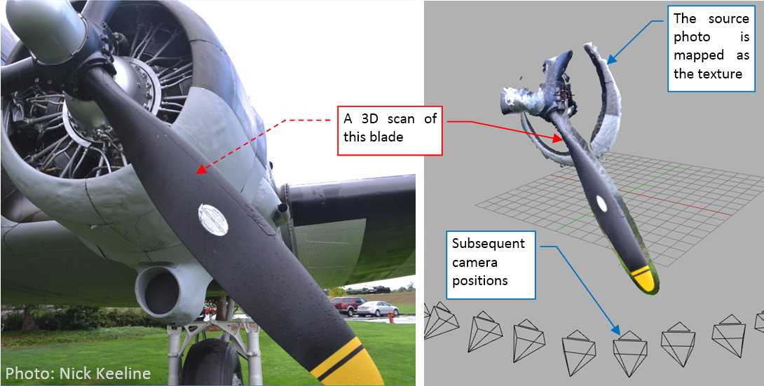
Note for the C-47 buffs: it seems that this aircraft used two different types of the Hamilton Standard blades. Most of the C-47s used wide-blade propellers, similar to those from the B-17 bombers. However, it seems that some of the C-47s used older, thin-blade propellers, which you can see in the aircraft from the picture above. For example, I have found similar blades in another C-47 from Commemorative Air Force, which was built in 1944.

NRK’s 3D scan recreates only the upper (i.e. forward) propeller surface and its leading and trailing edge. However, it is still usable, because in most of the blades from this era their lower (i.e. rear) surface was flat. In this NACA report 642 (from 1937) I have found some tips about the airfoil used in the Hamilton Standard propellers: it could be R.A.F-6 or modified NACA-2400-34. Because the NACA-2400 had convex lower surface, I ultimately decided to use the R.A.F-6 airfoil:

0066-02.jpg

R.A.F-6 is one of the pioneer airfoil shapes, designed in 1912. In that times engineers did most of the aircraft drawings with a chalk on the workshop floors. Thus the data points for this airfoil are relatively sparse, and leave some space for the handcraft – especially along the leading and trailing edges. I smoothed them using subdivision (i.e. B-spline) curves.

I connected this the R.A.F-6 airfoil to a circular base, creating in this way the initial segment of the propeller blade:

0066-03.jpg

Then I fit this segment into the reference mesh:

0066-04.jpg

As you can see on the picture above, the surface obtained from a 3D scan contains plenty of small irregularities. However, their presence helps to estimate the tolerance (i.e. the range of the shape deviations from the real surface) of this reference.

I formed the blade using the same methods as described in this post: by extruding and adjusting subsequent “ribs”. First I recreated the general contour in the front view:

0066-05.jpg

I formed the tip using the same methods as in this post: first I put an auxiliary circle (as an additional reference), then I connected the leading and trailing edges around this shape: 

0066-06.jpg

Then I rotated this blade a little, placing the tip surface on the reference surface: 

0066-07.jpg

At this moment the tip is the only fragment of the blade that fits the scanned surface: all the other blade segments are below or above it, because they are not twisted (yet).

I will twist this blade using curve modifier (as I did in this post). Thus I created such a curve: 

0066-08.jpg

Initially it was a straight line, placed on the blade axis (as in figure "a:, above). Simultaneously it lies on the rear (flat) blade surface (Because I placed all of the blade sections above its axis *– see the third figure in this post).

The blade of such a shape is not balanced – the centrifugal force would tore it off from the propeller hub. To avoid this effect, all blade cross-sections should have their centers placed on the blade axis. Thus in the side view the blade should resemble a symmetric triangle. I sketched its contours in figure "c", above) using white dashed lines. To fit the lower (rear) blade surface to such a line, I deflected the deforming curve downward (rotating it around the tip – as in figure "b", above). However, to simultaneously fit the blade upper surface to the top contour, I had to alter the thickness of its airfoils (see figures "c" and "d", above).

Figure below shows the resulting, “balanced” blade (it is still not twisted): 

0066-09.jpg

Finally, I twisted this blade by twisting subsequent vertices of its deforming curve. I did it until the leading and trailing edge fit their counterparts on the reference surface: 

0066-10.jpg

It was the last step of this process. You can find the resulting Hamilton Standard propeller blade in this source *.blend file.

Although it is still based on some assumptions (for example – the airfoil shape), this is much better approximation of the real shape than my previous attempts.

  • Member since
    June 2014
Posted by Witold Jaworski on Sunday, October 16, 2016 2:04 PM

This week I continue mapping the SBD-5 Dauntless skin panels onto my model. After tracing the outer wing sections, described in the previous post, I traced the center wing section:

0065-01.jpg

As you can see in the picture, I also traced the contours of the wheel bay on the wing surfaces. (These openings disappear, when you enter mesh edit mode, because they are dynamically created by Boolean modifiers. Thus such contours will be useful during further work, because in this way you can see these edges while editing the mesh).

I also outlined contours of the bomb bay panels, which are modeled separately “in the mesh” (every panel is a separate Blender object). I did it, because the panel lines that I draw on this image will be used as the input for various final textures. In some case I will use them as the source of “dirt” that occurs around every cleft in the aircraft skin. These thick lines will provide a decent effect on the textures.

Of course, I also used the reference photos to verify panel locations:

0065-02.jpg

When I compared panel lines in the photo and my scale plans, I discovered that I have to make some corrections. There was a significant difference in the size of the fuel line covers (see figure above). In the real aircraft they were somewhat larger than on my drawings.

In similar way I mapped the empennage panels. The growing number of identified differences between the reference drawings and real airplane forced me to use these panel lines as a kind of additional reference picture. That’s why I also decided to trace the ribs on all of the aircraft control surfaces.

Once I mapped these details, I started tracing fuselage panels. First I drew their “horizontal” lines that run along the longerons:

0065-03.jpg

Fortunately, it was quite easy, because during the modeling phase I intentionally placed some edges of the fuselage mesh along rivet seams. Now this effort pays off.

Then I verified these new lines on the reference photo. I discovered that while the aileron and elevator ribs on the photo match my scale plans, the rudder ribs have different locations:

0065-04.jpg

I also noticed another difference in the upper part of the tailplane fairing. Its outer edge runs along one of the fuselage longerons. In my model it is placed somewhat higher than in the photo:

0065-05.jpg

When the other fuselage lines match their counterparts on the reference photo, this difference means an error in the shape of my model. I analyzed this area, and I started to suspect that the gap between the real line and line on my model is caused by the difference in the fairing shape. However, to be sure, I needed more evidence to proof this hypothesis. I carefully checked all available photos of this area:

0065-06.jpg

Ultimately, I had found that the upper edge of the tailplane fairing is too high. In my model it overlaps the longeron line, while it should be adjacent to this panel seam. Lowering this edge will decrease the fillet radius in the upper area of the horizontal stabilizer fairing.

Well, it means that I have to revert to the modeling, and adjust the shape of this part:

0065-07.jpg

I did most of the modifications shown in figure above by shifting mesh vertices along their edges. Fortunately, this command has an “update UVs” option, which automatically updates the mesh UV layout. Thus when I updated the fairing mesh and I looked on its UV map, the mesh was already updated there. I just had to export it to the reference image, and shift few lines into new location (as in figure "a", below):

0065-08.jpg

After these modifications, fuselage panel lines match the photo (as in figure "b", above).

I had another kind of troubles with the lower part of the fuselage, behind the wing trailing edge. The UV layout of this mesh fragment has a significant distortion. A straight line on the model maps to a curve in this area. What’s more, I had to split this area (using seams) into two separate parts, which also creates some continuity issues:

0065-09.jpg

It was quite difficult to find a proper curve on the UV plane that transforms into a straight line on the model. This process required several iterations. After I managed to keep shapes of these lines within acceptable tolerance, I identified another difference between my model and the photos: a short seam below wing fairing trailing edge (see figure above). While in the real airplane it was a nearly straight line, in my model its rear part reproduces the conical shape of the trailing edge cross section. I suppose that this fuselage area had a visible deviation from the “ideal” conical shape, caused by the technological constrains. (It is difficult to apply such a more pronounced curvature, as you can see in my model, to the aircraft skin stringer). I will deal with this issue in the next post.

Figure below shows the complete set of the panel lines, mapped on the SBD-5 surface:

0065-10.jpg

I still have to map the differences that occur in the other Dauntless versions (SBD-1, SBD-3). Frankly speaking, I started to note some variations in the layout of the fuselage panels between various restored SBDs. Sometimes it is difficult to distinguish the real, historical differences between various versions from the side-effects of a particular restoration.

In this source *.blend file you can evaluate yourself the current version of the model, and here is the Inkscape file.

  • Member since
    June 2014
Posted by Witold Jaworski on Sunday, October 2, 2016 2:26 PM

I always start drawing the image of the aircraft skin by tracing the lines of the main panel seams. They will form a kind of reference “grid”, which later I will fill with other details: rivet seams, inspection doors, etc.

I will draw all these technical details in Inkscape, because it is much easier to modify such shapes in this vector-based program than in GIMP, which is mainly intended for the raster images. What’s more, I can export this scalable vector graphic from Inkscape to a raster image of any resolution.

Initially I prepared in Inkscape an empty drawing, set up its layer structure, and placed the appropriate links to reference drawings on the UV and Reference layers:

0064-01.jpg

I duplicated here the basic structure for the detailed bump map, which I worked out during my P-40B project. It is explained in all details in the “Virtual Airplane” guide (chapters 3 and 4 in Vol III, or chapters 6 and 7 in the complete edition). In this case I just used the hierarchical layers feature for grouping the related layers (in Panels, Fabric) together. (This feature was introduced in the latest Inkscape 0.9x, while the guide was written earlier, using older versions of this software).

Although I placed my scale drawings in the background, as the reference material, I will not treat them as the “ultimate truth”. Everybody makes errors, so do I. The only method to eliminate most of them is to check every detail as many times, as you are able. For example *– see the bent sheet metal strip that runs around the wing tip edge:

0064-02.jpg

When I sketched it on the scale plans, it was a minor detail. Its width was not much larger than the width of the thicker line that I used to trace the outer silhouette of the aircraft. Thus I did not studied the photos carefully enough in that time, and drew this strip too thin. Now I have an occasion to look on the source photos with a “fresh eye”, and correct the width of this strip. However, I cannot just offset the original contour from the scale plans. To match the UV layout of the wing, I have to give this curve somewhat different shape that follows the unwrapped area around the wing leading edge (as in figure above).

Well, there is no any “magic” way to do it: I have to keep open Inkscape and Blender side-by-side. In Blender I mapped as the texture the initial image exported from Inkscape (and turned on the option that displays it in the Object/Edit mode). Once I modified this wing tip curve in Inkscape, I had to export the whole drawing to a raster file, and then to reload it in Blender. Fortunately, such a transfer takes no longer than 2-3s. Such an arrangement allowed me to make quickly several iterations, resulting in the proper shape of the curve on the 3D model:

0064-03.jpg
To see better the lines on the model, I drew them in red. Fortunately, the rest of the panel seams runs across relatively flat areas, so they match the scale plans.

Of course, I also matched their locations against the reference photos (I set up them some months ago, and described it in this and subsequent posts):

0064-04.jpg

Fortunately, there were only slight differences, which I quickly introduced to my Inkscape drawing. Such a “double-check” ensures, that the lines are in the proper places, and I can safely fill this image with minor details. However, the common sense tells me, that I should map the panel seam lines on the whole aircraft, first. There is always a chance that I will encounter something unexpected during this process.

Dauntless had large wing flaps, and one of their prominent features were the rounded holes, that perforated their surface. Distribution of these holes determines the location of the internal reinforcements of these flaps, and the corresponding rivet seams. Thus these holes are as important as the panel seams. I started to draw their first row using a special, dotted line:

0064-05.jpg
 
Although Inkscape does not offer any UI for user-defined dotted lines, I used its XML Editor feature to create a dotted line pattern that matches the holes in the Dauntless flaps. I used here the same method that I worked out for the rivet seams. (See “Virtual Airplane” guide, Figure 3.1.11 in Vol III, or Figure. 6.1.11 in the complete edition, and the further pages referenced there).

Once I drew the first row, I matched it against the reference photos (Figure 64‑5). After a few iterations I received a satisfactory approximation. (Due to various unknown second-order photo distortions, there location of these holes is a kind of “compromise” between various photos and the known location of the flap ribs. The latter were explicitly dimensioned on the Dauntless stations diagram, as you can see Figure 8-3 in this post).

When I matched the first row of the holes, I copied them into another two rows, which I matched against the photo. The final results differ from my scale plans:

0064-06.jpg
 
It looks that on my scale plans I made a kind of systematic error in calculating ribs stations from inches to drawing pixels. (Since that time, I already made numerous adjustments in this area – see Figure 15-8 in this post, Figure 17-5 in this post, and Figure 31-5 in this post).


The general panel layout on the wing top surface is similar to the panels on the bottom. Thus I copied (and mirrored) their lines from the bottom surface. It required just a few minor adjustments to match their drawing to the photos of the wing top surface:

0064-07.jpg

(I was really happy that I did not have to match again the wing tip strip against the photo. The curve copied from the bottom surface fits the top surface quite well).

For the further test, I created a copy of the texture image with a semi-transparent background. It makes the model surfaces transparent (as in figure "a", below):

0064-08.jpg

I used this effect to check if the panel seams that runs along the wing spars on the top surface match their counterparts on the bottom surface (as in figure "b", above). (It will be useful, when I start to recreate the wing internal structures).

During further checking of the results, I noticed a minor error on the leading edge:

0064-09.jpg

This is a side effect of the corner in the mesh seam, which does not run along a “sharp” (Crease = 1) mesh edge. Unfortunately, I have to keep this edge smooth, because it controls the proper shape of the wing leading edge, especially in the top view. There are two solutions: 1. add two additional “ribs” on both sides of this wing tip rib, to remodel this mesh fragment, 2. create the strip along the wing tip as a separate object, and placed it on the main mesh. I still have to decide, which solution is better.

Figure below shows the results of this week: the panel lines of the wing and the image of the flap perforation:

0064-10.jpg

In this source *.blend file you can evaluate yourself the current version of the model, and here is the Inkscape file.

Next week I will map at least the wing center panels and its flaps perforation. (Maybe I will do more – but I am still short of time due to a certain project in my daily job).

  • Member since
    June 2014
Posted by Witold Jaworski on Saturday, September 17, 2016 3:05 PM

The progress of my work in this month will be relatively slow, because I still have some additional activities linked to my “daily” job. Nevertheless, it is going on.

The original texture map (UV map) finished in the previous post (as in figure below) is appropriate for the color textures (camouflage, national insignia and other markings). In this mapping various parts of the airplane overlap each other, so the pattern of the test image remains continuous:


While such an arrangement makes the camouflage painting easier, it would be impossible to use such a map with overlapping elements for another important texture: the image of the aircraft skin details. In this post I will shortly describe, how I prepared an alternate UV map for this purpose.

I am going to recreate all the panel seams, rivets, and hatches that you can see in the reference drawings using a height (bump) texture. The final effect will look as good (or even better) as with the details modeled “in the mesh”, while drawing these elements in 2D is much simpler and requires less work than the modeling in 3D. What’s more, I will use this image as the base for other important textures (reflection texture, transparency texture).

I prepared for this texture an alternate UV map:


To get decent results even in the close-ups of the final model, I need for the texture of the technical details a high resolution image. The simplest way is to enlarge the image, but it consumes the computer memory and increases the rendering time. To make better use of the available image space, I “packed” all the airplane elements more tightly. I also used another trick: because the left and right side of this airplane differ only in a few relatively small areas, I decided to map here only the left side of this model. I will use the same map for the right side. Later I will map the few faces from the right side that contains the differences in the empty fragment of this image.

To determine new size and locations of all model parts on this new map, I copied in Inkscape the UVMap layer (see previous post) with all its sublayers. I named this alternate map UVTech. I played for a while with the wings and main part of the fuselage. Ultimately I decided that I have to enlarge their size by uniform coefficient: 130%. The same coefficient applies to all other model parts. (The most important thing is to keep all these elements in the same “scale”. Otherwise you would have on the final texture rivets of different sizes, and other, similar errors). Then I moved and rotated some of the model elements, fitting them into the available space. In this way I created the first approximation of the new alternate UV map:


Using fragments of the scale plans, I also prepared an alternate reference picture that matches this layout (you can find it in the Blender file, linked at the end of this post). I used both of these pictures in creating this UV map in Blender.

To create an alternate map (named “UVTech”) in Blender, I had to repeat following steps for every mapped mesh in the model:

  1. Copy the existing UVMap into new map, and rename it to UVTech:


  2. Resize the mesh faces on this new map by 130% (I typed the exact value of “1.3” using the keyboard input feature):


  3. Place the enlarged mesh faces as in the reference drawing:


Sometimes during this process I introduced small improvements: for example, I decided that I can shrink the areas on the control surfaces leading edges. (They do not contain any details, and are obscured by the wing or the stabilizers). It allowed me to fit these elements into the reference drawing:


When this work was over, I replaced the contents of the UVTech layer in Inkscape with the final shape of the UVTech map. (I exported it from Blender as an SVG file, as I did in the previous post).

In this source *.blend file you can evaluate yourself the current version of the model, and here is the Inkscape file.

In next week I will start to draw the image of the technical details of the aircraft skin.

  • Member since
    June 2014
Posted by Witold Jaworski on Saturday, September 10, 2016 2:03 PM

After a long break in August and September (I had to finish a demanding project in my daily work) I am back. This week I made a “slow start”: because in my last July post I finished mapping the SBD-3, now I mapped in the UV space parts that are specific to the alternate Dauntless versions: SBD-1 and SBD-5.

Let’s start with the SBD-1: when you switch into its scene, you can immediately see the gray elements that are not mapped in the UV space (as in figure "a", below). These parts are specific for this version:

0062-01.jpg


It did not require a lot of work *– just to unwrap few additional meshes in the UV space. You can see them in figure "c", above). I placed their faces in the same location, as their counterparts from the SBD-3. In figure "b", above, you can see the SBD-1 model after this update.

Then I had to make similar work in the SBD-5 scene. The engine cowling of this model contains more differences, thus it required much more work:

0062-02.jpg


When all the meshes in all SBD models were unwrapped, I had to export them into a 2D drawing. (I will need such a picture as a reference for painting various textures). I prefer to keep it as a scalable vector drawing, thus exported it into an SVG picture, which I can edit in Inkscape:

0062-03.jpg


The standard Blender command allows you to export only the single mesh of the active object. Some years ago I wrote an add-on which exports into SVG all selected objects at once. (You can find this add-on and learn how to use it in the III volume of this guide). It is extremely useful for such a model built from multiple objects, like this one.

Inside Inkscape I placed the exported objects onto a layer that has the same name as the defualt UV map in Blender: UVMap. (In the next posts I will prepare in Blender some other alternate UV maps, thus this naming convention is important).

Internally, I split in Inkscape the contents of the UVMap into five sublayers:


0062-04.jpg


Two bottom layers (Color, Common) contains the elements that are common to all three models. I created Color layer for the future use. It contains just the fixed parts of the wing. I am going to use a separate texture for the national insignia and various technical labels. On some SBDs the stars on the wing lower surfaces were so large that they will require the seam line directly on the leading edge. Thus for this purpose I am going to create an alternate UV map for the wings. I will place it in Inkscape on additional Decals sublayer. Then, to create the UV layout for the insignia texture, I will hide the Color layer. When I will need the UV layout for the camouflage texture, I will turn off the Decals layer, and make the Color layer visible.

Why I did not simplify this drawing, creating in Inkscape a separate layer for each texture that would contain all the required objects? Because in such a case I would have to duplicate all of the common objects – sometimes several times.

The progress of my modelling project is not like a “waterfall”, it more like a spiral. From time to time I have to return to a finished stage, and fix something there. That’s why I always try to have just “one string that controls all”: in this case it means having single instance of every mesh in the Inkscape drawing. When I have to modify something in the corresponding Blender mesh, I will need to update just single element in this drawing, instead of multiple instances in the “simpler” version.

I use the same method as described above for obtaining the UV layout for a particular Dauntless version. There are three sublayers, named: SBD-1, SBD-3, and SBD-5. In each of them I placed just the elements that are specific for these version. For example, the figure below presents contents of the SBD-3 layer:

0062-05.jpg


When you combine it with the basic layers (Color, Common), you will get the complete UV layout for the SBD-3:

0062-06.jpg


(Of course, at this moment this layout contains only the left side of the model. I will update it later, adding the elements from the right side).

In this source *.blend file you can evaluate yourself the current version of the model, and here is the Inkscape file.

  • Member since
    June 2014
Posted by Witold Jaworski on Monday, July 25, 2016 6:45 AM

This week I finished mapping all the parts of my model onto a two-dimensional image. Figure below shows the test image, mapped on the model surface. (Its pattern helps me in keeping the same mapping “scale” for each object):

Posted Image

I did not “unwrap” the small details, like the parts of the propeller mechanism, because I will “paint” all the small parts using procedural textures.

Figure "a", below, shows how these meshes are distributed on the 2D UV map (you can see the reference image beneath). At this moment I mapped just a single (left) wing, the symmetric halves of the rudder and the fin, as well as the left side of the fuselage. The upper and lower part of the tailplane are symmetric, so I just mapped its left, upper side. I will create the other sides and symmetric elements later, at this moment I just reserved the necessary UV space for these objects.

Posted Image
In figure "b", above, you can see that the reference image looks like the first approximation of the skin details. In the next post I will draw an image of these details that fits these unwrapped meshes. It will be the base for all the textures I will create for this model.

In the rest of this post I will shortly describe my typical approach to UV mapping.

This post is not intended as a detailed step-by step guide. If you want such an introduction “for the absolute beginners”, use this book. It is accompanied by many useful Blender add-ons, for example an add-on that exports all the unwrapped objects into such an SVG image, as shown in figure "a", above. (In the standard Blender you have to export each object separately).

Let’s analyze the wing case. I am going to map its upper and lower surface separately. Thus I defined two auxiliary vertex groups, to easily select these mesh parts:

Posted Image

I use the Project From View command to create initial mapping. For the upper wing surface I use the projection from the local top view of the wing object:

Posted Image

I shifted and scaled this shape, fitting it to the reference image. I used “pinned” vertices from the flat part of the wing surface to this image (using the Pin command). Then I invoked (in the UV/Image Editor window) the Unwrap command:

Posted Image
It “relaxes” (unwraps) all the faces that are not pinned. In this case Blender unwrapped the leading edge and wing tip edge.

I unwrapped the wing bottom surface I the same way. At this moment the seam line between the upper and lower wing surface lies in the middle of the leading edge (figure "a", below). While it is OK for the relatively sharp edge around the wing tip, the minimal discontinuity of the texture image on the most exposed, forward part of the wing would spoil this model. Thus I usually hide such a seam, leading it along the nearest panel seam line on the lower wing surface (figure "b", below):

Posted Image
When I marked the seam line, I called another Unwrap command. In response, Blender “teared” the bottom part of the leading edge from the lower wing surface, and “glued” it to the upper surface:

Posted Image
As the final touch, I straightened the rib edges (it is much easier to draw the texture images on such an “orthogonal” wing layout). The only exception is the skewed inner edge of this wing segment:

Posted Image
When the wing surface was mapped, I replaced the reference image with the standard Blender test image (UV Grid). It is prepared for finding eventual mapping distortions:

Posted Image

As you can see, there was a serious distortion along the leading edge seam.

The remedy for such a flaw depends on the mesh local conditions. When it occurs on a flat surface, you can make the seam line sharp (setting its Crease coefficient to 1.0). However, in this case it would spoil the cross-section of the leading edge. The other, less preferable solution is to insert an additional, perpendicular edge loop. When you locate it in the proper place, it efficiently removes such a distortion:

Posted Image

(I do not like creating such additional edge loops, because each of them makes the resulting mesh topology more complex. However, sometimes you have no choice, as in this case).

In this source *.blend file you can evaluate yourself the current version of the model (as in the first illustration from this post).

  • Member since
    June 2014
Posted by Witold Jaworski on Saturday, July 16, 2016 3:50 PM
Because of the holiday break, during July and August I will report my progress every two weeks. I will return to weekly reporting in September.

I have just begun the third stage of this project: “painting” the model. At this moment I am unwrapping its meshes in the UV space. I will deliver you a full post about this process next Sunday. Today I will just signalize how it looks like.

So I started by creating a new reference picture. It had to have a rectangular shape. Inside I placed my drawings of the fuselage, wings, and the tailplane:

The most important thing: all elements of this drawing have exactly the same scale. As you can see, I used flipped left side silhouette in place of the right side view. In fact, I should prepare a 2D drawing of the right side view first, then place it here. On the right side of the Dauntless fuselage, the steps to the gunner’s and pilot’s cockpits were located in different places. There was also a rectangular hatch of the luggage compartment. However, I am a little bit lazy, and I prefer recreating these details directly on the final textures. I will describe what I mean in August, when I report how I drew it.

I use the reference images to keep the proportions between all unwrapped model parts. Sometimes it is also useful for hiding the seams, as in the case of these wings:


I split the mesh into the upper and lower surfaces, and mapped it onto the corresponding parts of the reference drawings. On some textures (for example: the camouflage) it will be impossible to obtain an ideal continuation of the picture mapped along this seam. It is not a problem on the sharp edges, like the wing trailing edge. However, the rounded leading edge is a different case: I prefer to keep it “in one piece”, hiding the texture seam in the first original panel seam on the lower surface of the wing.

When the mesh is mapped on the reference picture, I use another, standard test picture to ensure that the mapped image is not deformed


At this moment I have already unwrapped most of the model:


I still have to unwrap the engine cowling. When I finish it, I will publish a full post about this process, as well as the updated model. (I will do it on next Sunday — July 24th).

In this guide you can find detailed step-by-step instructions how to map various aircraft model meshes onto texture images, as well as all other details of “painting” the digital models.
  • Member since
    June 2014
Posted by Witold Jaworski on Saturday, July 9, 2016 3:09 PM

In the previous post I promised that I will start the UV-unwrapping. However, last week I found a new edition of Bert Kinzey’s “SBD Dauntless” book. After ten years break, Bert started to continue his “Detail & Scale” series, this time in a different form: digital editions. This e-book is the “updated and revised” version of an earlier publication (from 1995). For me, the most important part of Kinzey’s books are the “walk around” photos. They differ from all other “walk arounds” by careful selection of the pictures and comprehensive comments that explain many technical details depicted on these images. Usually these comments are as important as the photos.

Posted Image

Take for example such a caption that you can find on page 102, below the picture of the forward firing guns (as in figure above):

All versions of the Dauntless had two fixed, forward-firing, .50-caliber machine guns which were fired by the pilot. This photograph was taken from the Pilot’s Manual for the SBD-2, and it shows both of the two fixed guns in place. However, the manual also states that the left side gun was usually removed from the SBD-2 in order to save weight. This was done only on the SBD-2 and usually only during peacetime. Once the war started, the additional firepower of the second gun was more important than the weight advantage gained from deleting one of these guns.

It is a great clarification that cites a reliable source: the original manual. In the other books on this subject you can find various, often contradictory versions about the SBD-1 and SBD-2 forward guns. For example:

Pilots’ armament [of the SBD-2] was increased from one to two .50 caliber guns (Barret Tillman, “The Dauntless Dive Bomber of World War Two”, Naval Institute Press, 2006, page 8);

This statement implies that the SBD-1 had a single 0.50 gun! (And it does not tell us about the source of this revelation).

Another one:

To retain the center of gravity (CoG) position [in the SBD-2], one of the forward-firing machine guns was removed (Robert Pęczkowski, “Douglas SBD Dauntless”, Mushroom Model Publications 2007, page 8);

This statement implies that all SBD-2 had a single 0.50 gun because of the design reasons (aircraft balance). This is also an information without specified source.

You can find in the Web many other descriptions of the SBD-1 and SBD-2. I remember that I encountered somewhere yet another variation of this story. It stated that the pilot in the SBD-1 had two smaller, 0.30-caliber guns.

I am really happy that Bert gives us the ultimate answer on this issue. (In another place in his book he mentions that for this writing he used the six original manuals, one for every Dauntless version. That’s why I take for granted his statement that all SBDs had two 0.50 forward guns).

In the chapter about wings (page 85) I found the confirmation of my hypothesis about the overlapped flap edges:


Posted Image

Compare figure above with the second-last picture from my post from previous week. This was a result of the deduction, because when I wrote it, I had no such a vertical photo of the wing with closed flaps.

However, when I studied the photos of the cockpit canopy, I noticed a difference in the shape of the rear segments:

Posted Image

Figure "a", above, shows a fragment of the photo, taken from above. It reveals that the upper part of the last segment had a cylindrical surface, and the radius of the cross section between the third and the last canopy segment was larger than in my model (shown in figure "b", above).

It was further confirmed by all other photos: the side edges of all cockpit canopy segments were parallel, while in my model they are not:

Posted Image

I had to be blind that I did not noticed this mistake before! In fact, it happens when you stick too much to your assumptions about particular shape. In such a state of mind you can see only the details that confirm your hypothesis, and neglecting the others. I assumed that the top radius of the subsequent canopy segments decreased like in the telescope tube: each segment has smaller radius than the previous one. In the effect I received much smaller radius at the end of the third canopy segment than you can see on the Detail & Scale photo.

As the first approximation of this radius I placed inside the model an auxiliary circle (Figure "a", below):

Posted Image

I fitted this circle between the sides of the previous segment and decreased it by an appropriate clearance. Then I checked how it looks in another reference photo (Figure "b", above). In this way I have found that it should be slightly smaller. Thus I started to search for the reason of such a result.

BTW: I used the same reference photo before, to verify the pervious cross section. I determined then that it had much smaller radius than the result presented above. This situation shows that you always have to double check every model element on multiple pictures!

Finally I think that I found the reason: the canopy sides should have a little less steep slope in the rear view. The error comes from the wrong assumption about the shape of the pilot’s canopy:

Posted Image

I assumed that the upper horizontal “sticks” of this canopy frame were nearly parallel to the fuselage centerline. In the effect the front and the rear edges of this segment were not parallel (figure "a", above). The photo from Detail & Scale book reveals that I was wrong (Figure "b", above). You can see on this shot from above that both horizontal elements of this canopy frame are parallel to the cockpit border edge. Thus I had to rotate a little the rear edge of the pilot’s canopy, making it parallel to the front edge. It forced me to decrease (by scaling) the radius of the arc that closes the upper part of this canopy. In the effect, I will have to decrease the corresponding arcs in all subsequent canopy segments, including the last segment. As I mentioned in one of the previous posts, I tried to avoid such things, but nevertheless I am prepared: the meshes of my model are relatively simple, so such a modification is not a great problem.

If you want to create a precise copy of any complex object, be prepared that from time to time you have to step back and alter the shape of some finished elements. The work on such a model more resembles a “spiral” than the classic “waterfall” process.

Well, I documented these small bur laborious modifications on the pictures below. Generally, in each canopy segment I had to rotate the side faces along their base (see it in the second segment, depicted in Figure "a", below). Then I scaled down (a little) the upper faces of such a mesh, decreasing in this way the cross-section radius of the resulting surface.

Posted Image

The third segment was more difficult, because the radius of the top arc in its cross sections increases toward the rear (Figure "b", above).

The most difficult part was the last, fourth canopy segment (see the picture below). First I formed its faces in the rotated position (figure "a", below), ensuring that it properly slides into the previous segment, and that its upper part forms a clean cylindrical surface:

Posted Image

Then I rotated it back into “closed” position, and verified all other details (figure "b", above). Fortunately, it seems that the radius of its rear edge did not significantly change, and it still fits the rear border of the cockpit. (It still looks like in the reference photos). The biggest change occurred in the frontal cross section of this canopy segment.

Indeed, I already altered this radius before: see this post, Figure 57-5. You can see that I made a wrong decision that time, decreasing this section instead of increasing the rear edge of the previous canopy segment. This is a typical “fitting” error, which occurs quite often!

Figure "a", below, shows the modified shape of the cockpit canopy:

Posted Image

Figure "b", above, shows the same canopy with the updated frames. It is hard to notice any of my changes in this side view, isn’t it? In fact, fitting anew the frame meshes to the altered canopy segments required even more time than the adjusting of the canopy basic shapes! I am really happy that some posts ago I managed to tame the temptation to recreate the internal frames of these canopies. Now I would have much more work with them.

That’s why I am going to recreate all the internal details in the last, fourth phase of this project. In this way I am just creating “time buffer” for eventual new findings, like this one.

Of course I checked the updated canopy on the reference photos. This time I did not want to be blind on eventual differences — as you saw in this post, even slight distance between the model and the photo can indicate a significant error. I slid all the canopy segments into “open” position, to compare them to the CAF photo (this photo has the highest available resolution - see figure "a", below):

Posted Image

To better see the model on this picture, I assigned a red material to these frame objects. As you can see, most of the canopy frames match the photo. However, there are two exceptions, on the pilot’s cockpit canopy. The bottom ends of the middle and rear frames seem to be shifted (by about 0.2” and 0.3”). It could mean that the slope of these canopy sides had a slightly different angle. However, the front edge and the rear edge of this segment match the photo (figure "a", above). At this moment I will leave this difference unresolved — maybe in the future I will find something, which will help me to explain this difference.

There are also slight differences in the last canopy segment (figure "b", above). However, I think that I can explain them now. This part of the cockpit canopy has two degrees of freedom: you can slide it as well as rotate around its corner. The canopy in figure "b" seems to be rotated by about 0.5⁰. Such a small rotation can be within the tolerance of its lock mechanism. It can be caused by the gun doors, which seem to be slightly opened in this photo. There is also a thick rubber (or leather) strip around the rear edge of this canopy segment. It seals the rear border of the cockpit. (I will recreate it later). I think that the influence of the gun doors and this strip can rotate of this last canopy segment by such a small angle.

In this source *.blend file you can evaluate yourself the current version of the model, described in this post.

This post ends the “modeling” stage of this project. During this phase I formed the general shape of the model, and created all the surfaces which require the classic “image” textures. In the next post I will unwrap these surfaces in the UV space, preparing them for the “painting”. For all other details that I will create during the last, “detailing” phase, I will use procedural textures, which do not require UV-mapping. (The only exception are certain elements of the cockpit interiors, like the instrument panels, but they will have their own, separate texture images).

  • Member since
    June 2014
Posted by Witold Jaworski on Saturday, July 2, 2016 2:32 PM

While working on the cowling details, I discovered that the SBD-5 from the Commemorative Air Force (“white 5”) uses a non-original Hamilton Standard propeller. It has larger hub and a pair of bolts in the middle of the hub barrel edges. (As I wrote in this post, the original Hamilton Standard hubs used in the SBDs were smaller, thus they had a single bolt in the middle of each barrel edge). What’s more, I also noticed that the centerline of my model does not precisely pass through the tip of the propeller dome visible in this photo. When I corrected this mistake, I also noticed that the edges of certain cowling panels in my model are minimally below their counterparts on the photo. I examined this difference and decided that I should fix it by rotating the camera of this projection around the fuselage centerline. It was really a “cosmetic” adjustment — the rotation angle was about 0.7⁰. However, suddenly everything in this model matched better the reference photo — except the horizontal tailplane:

Posted Image

When I previously matched my model to this photo (see Figure 42-9 in this post), I aligned it along its horizontal stabilizer. (I assumed that it is not deformed by any significant load). It seems that I was wrong: the Dauntless on this picture is taking off (its wing flaps are retracted). What’s more, its elevator is slightly rotated upward, what means that this airplane has already gained enough speed and currently the pilot is lifting its nose to leave the ground. Thus there is an aerodynamic force which bends the tailplane downward, while the lift force tries to bend the wingtips upward:

Posted Image

I think that I would obtain a perfect match between the fuselages of my model and in the photo by placing the viewpoint of this projection between its previous and the current location. (In its previous location it matched the deformed tailplane, while in the current one — it matches the deformed wing).

However, both of these tailplane and wing deformations are small. Thus aligning the wing of my model to the wing in this photo delivers me much more useful information, than a “geometrically pure” match somewhere between these two points. The influence of viewport rotation of 0.7⁰/2 = 0.35⁰ on the fuselage can be neglected, and now the only part of my model that does not fit the photo is the tailplane. It’s OK, because in this projection I cannot see any special details on this element. On the other hand, now I can use this high-resolution photo to check various details on the bottom side of the wing.

Currently we are close to the end of the modeling stage of this project. All the elements of this model that I am going to ‘unwrap’ for the image textures are already in place. Now I will use this high-resolution reference photo to re-examine the model shape and fix all the remaining differences. I started from the empennage:

Posted Image

I fixed it working directly on this picture (I restricted the movement of the mesh vertices to the global YZ planes).

Then I shifted forward, fixing the dorsal fin:

Posted Image

There still was a difference in the tail bottom contour. This time I had to alternate the lower part of the tailplane bulkheads:

Posted Image

I did it by scaling these parts of the bulkheads downward. The most difficult part of this operation was the preservation of the straight lengthwise (“longeron”) edges in the rear part of the tail.

Of course, I also used other photos for this check. In the figure below you can see matching the wing against a “semi-vertical” shot of a Dauntless in a steep bank (most probably in a tight turn):

Posted Image

I can see here a difference in the wingtip shape. However, I already verified it against other photos, several months ago (see Figure 31-8 in this post). What’s more, I discovered that when I slightly rotate the wing tip around the wing span axis, it perfectly fits the photo (figure "b", above). Thus I again started to think about the forces — this time acting on these wings in such a turn. The lift force has to counter the centrifugal force here. For such a steep bank it can be several times greater than the weight of the aircraft. Thus the wing in this photo is under extremely heavy load, and it wing tips can be twisted as severely, as those in figure "b", above). Ultimately I assumed that this is an effect of dynamic deformation, and I should not modify the wingtip. (The photos of this wing in static conditions do not confirm this shape).

However, in figure "c" above you can see another difference that has haunted me for a long time: the gap between the wing flaps and the aileron. On the various photos, both static and in-flight, it seems that the trailing edge of the wing flap was a little bit shorter than in my model.

First I checked if in this photo the flap is not shifted nor rotated:

Posted Image

I placed auxiliary lines on the flap surface of my model. They go along the last row of holes in each of the 6 segments of this flap (figures "a", "b" above). These lines reveal the “natural” direction of the flap ribs. At the outer end of this flap I put a polyline, which upper edge matches the flap upper. (I wanted to check if this edge is parallel do the flap ribs).

Then I put the wing and these auxiliary lines flat on my reference drawings (i.e. I set the wing dihedral and incidence angles to 0). You can the result in figure "c", above). It seems that the middle sections match my reference drawings (and my model). However, the most inner section (containing the four rows of three holes in each row) should be slightly wider, while the most outer section was shorter (although it contains the same number of holes!). This result was a little surprise, because when I drew these scale plans, I assumed that the spacing between the flap holes was constant. (It would be easier to machine such a perforation). Now it seems that this distance varies in different segments of this flap! Finally, the polygon on the outer end of the flap clearly indicates that its outer edge is oblique (as in figure "c", above).

Of course, I verified these findings in other reference materials:

Posted Image

The close-up photos of various aircraft confirmed that the outer edge of the upper flap was slightly oblique (figure 'a", above). I can also see that the distances between the rows of holes in the last flap segment were shorter than in the segments in the middle. (It implies that the spacing between these rows in the most inner segment could be also a little bit wider). What’s more, I could see these differences in one of the original Douglas drawings (figure 'b", above). However, I neglected them before, because this is not a regular, orthogonal view. (Such a drawings can be often deformed in various ways).

Thus I modified the aileron and the flap according these findings (figure "a", below). When I attached wing to the centerplane (i.e. when I set its incidence and dihedral angles) I discovered that the corresponding aileron and flap edges became vertical in the rear view (figure "b", below):

Posted Image

An additional headache was the outer edge of the bottom flap, which was parallel to the last rib (figure "c", above). Ultimately I decided that most probably the outer corners of the upper and lower flaps overlaps as in figure "b", above).

Of course, I reviewed the whole model and made much more minor adjustments. I will not bother you describing them all. Fortunately, most of them did not require as much work as this small gap!

Figure below shows the resulting SBD-5 model:

Posted Image

In this source *.blend file you can evaluate yourself the current version, described in this post.

In the next post I will start the “painting” stage of this project. I begins with mapping of the texture coordinates (UV) onto the model surfaces (so-called UV-unwrapping).

  • Member since
    June 2014
Posted by Witold Jaworski on Saturday, June 25, 2016 2:43 PM

The last details that I create in this project stage are the gun doors behind the gunner’s cockpit. In the SBD-1 they covered a single Browning gun. Fortunately, they were wide enough for stowing the double guns, which were mounted in the SBD-2 and SBD-3 by the Navy workshops:

Posted Image

Note that stowing the ammunition belts of this double gun required additional cutouts in the cockpit rear border. They were covered by slide plates on both sides of the gun doors (see figure above). In this post I will recreate these details.

Before I do it, I have to fix a certain error that I have recently found: the shape of the tail cross-section, near the cockpit edge. When I formed it, I relied on the photos from a certain restoration project (as in figure "a", below):

Posted Image

The upper part of the first bulkhead behind the cockpit (at station 140) in figure "a", above was shaped along a single, gentle arc/curve. Looking on the other photos I assumed that in the front view the gun doors formed an arc, and this arc smoothly joins the curve of the bulkhead contour at the hinge line. Basing on these assumptions (marked in figure "a", above) in blue), I prepared appropriate mesh topology (as in figure "a". below). I created a “sharp” edge along the future gun doors hinge line, which enables me to cut out the inner area for the gun doors (as you can see in this post, Figure 24-9).

However, since that time I still had an impression that something is wrong with this tail shape. Finally, when I started to look at the sliding panels behind the gunner’s cockpit, I found that their cross-sections are different than I expected. I have found the ultimate confirmation in the picture from SBD-1 manual (figure "b", above). The top arc of this contour had larger radius, and its endpoints were outside the hinge lines. It was smoothly combined with a straight contour segment, spanning from the topmost longeron of the fuselage (the same that runs along the canopy side border).

Well, great! This means that I have to modify the concept of the mesh topology for this area in my model! Figure "a", below, shows the original layout, while figure "b" shows the modified mesh:

Posted Image

The enlarged arc of the tail cross-sections forced me to shift the mesh edges away from the gun door hinge line. In the effect, I had to switch to the “plan B” for this opening: I will create it using a Boolean modifier. (Never mind, I was going to use it anyway during the detailed phase, for the other openings in the fuselage).

To better fit the fuselage to the straight edges of the gun doors, I already placed their hinges on the tail upper surface (figure "a", below):

Posted Image

I tweaked the mesh edges around the cockpit rear border, obtaining the shape that closely resembles the original part in the reference photos (figure "b", above). However, I do not like their complex topology: such a thing can be an obstacle for eventual further modifications.

After this, I decided to verify how the last cockpit canopy slides under the previous segment. (This is another test before I start to work on the cutouts in the tail surface). In general, the gunner had to rotate it first into horizontal position, then slide it under the previous canopy (figure "a", below):

Posted Image

However, when I started sliding it, I had to stop: its rear edge was too wide (figure "b", above)! It seems that its radius is exaggerated: it was larger than the radius in the forward section of this canopy (figure "a", below):

Posted Image

Well, I adjusted the size of this last section, so that in the rotated position the last canopy segment fits the previous one (figure "b", above). Of course, then I also had to adjust the corresponding frame object to this new glass shape. I definitely should check it earlier! On the other hand, after this modification the gunner’s cockpit of my model better resembles the original photos.

The decision of using the Boolean operator for the gunner’s opening allows me to simplify the fuselage mesh (figure "a", below):

Posted Image

As I mentioned earlier in this post, I was not satisfied with the complex topology of the cockpit rear border. Now I decided to create it as a separate panel (i.e. separate object). It will differ between the SBD-1 and the later SBD versions, because in the SBD-1 (and SBD-2) the fuselage did not have the side cutouts (compare the first figure from this post and figure "a", below). That’s why the auxiliary “cutting object” for the Boolean operation has a shape that resembles the “T” letter (figure "b", above). In this way I created the main fuselage part that fits all the SBD versions. The topologies of both meshes — the fuselage and the rear panel around the gunner’s cockpit — became simpler. It means that it will be easier to introduce eventual further modifications.

Posted Image

There was an issue with the internal hierarchy of this model: the fuselage could not be the parent of the auxiliary “T”-like object, because it “cuts” its shape. (Such an arrangement causes problems with displaying the model — I already encountered it in the case of the wing fixed slats). The obvious solution was to assign both objects used by the Boolean modifier to a common parent. In the case of the wing it was its root rib. However, so far this main part of the fuselage was the root object of the whole model hierarchy. To resolve this problem I decided to create a new root: an Empty object. Because I will need it for posing the airplane in an eventual final scene, thus I placed it on layer 19, among other auxiliary handles (figure "b", above).

After these preparations I was finally able to make the sliding panels and their rails:

Posted Image

I used the reference photos to precisely recreate these elements. (The picture of a SBD-5 wreck in the figure above comes from Pacific Aviation Museum Pearl Harbor. I decided that when I work with the details, I can more trust the wrecks than the restored aircraft). The cutout for the ammunition belt was made between two fuselage stringers and the bulkhead at station 140 (see figure "a", above). Note that it creates a triangular hole between the sliding plate and the canopy rear frame (figure "c", above). Ultimately it was covered by a rubber band, attached to the canopy. (I will recreate it during the detailing stage of this project).

I created the sliding panel from a rectangle, which received the oblique forward edge. Initially I created the shapes embossed on its surface from separate cylinder halves. Then I recreated the faces around their edges, integrating these shapes with the base plate.

The “rails” of this sliding panel were made from simple duralumin stripes, folded inside. They were riveted to the fuselage stringers. Because these rails had to be parallel to each other, the axis of the fold in the bottom rail was deflected from the stringer axis (figure "b", above). That’s why this element had a wedge-like shape.

The archival photos revealed that there was also an alternate version of the sliding plates, which appeared in the SBD-3s. You can see it in the figure below:

Posted Image

I think that the photo in figure "a", above, was taken during operation “Torch” (November 1942), because the star on this picture has a wide light outline, most probably in yellow. Note that the gun has no armor plates there, and the sliding panel has no embossed stiffener along its rear edge. Figure "c", above, shows such a panel in a restored aircraft. (I have found it in the photos from the Kalamazoo Air Museum). We can see clearly here that the lower rail strip is not folded like in the previous figure, but just bent upward, and it is riveted to the stringer along its lower edge. This means that this sliding panel is somewhat narrower than the one from the SBD-5. (Why? Because the lower edge of this panel lies above the stringer axis, while in the SBD-5 it is slightly below the stringer axis). I suppose that it can be a field modification of an original SBD-3, adapting it for the double gun. However, I am not sure that all the SBD-3s had such sliding plates. Anyway, I recreated it in my SBD-3 model. The other version of the sliding panel, as in the previous figure, you can find in the SBD-5 model.

In this source *.blend file you can evaluate yourself the SBD-1, SBD-3 and SBD-5 models from this post.

  • Member since
    June 2014
Posted by Witold Jaworski on Saturday, June 18, 2016 2:57 PM

I continue updating the Dauntless versions that I am building in parallel to the basic SBD-3. In the previous post I updated the one important element of the SBD-5 model: its propeller (SBD-3 used an older version of the Hamilton Standard propeller). In this post I will continue this update.

While I already recreated the SBD-5 NACA cowling (see Figure 46-8 in this post), now it is time to adapt the panels behind it. I started by copying the corresponding cowling from the SBD-3. When it appeared in the place, I discovered a 1” gap between this cowling and the SBD-5 inner cowling panel (see figure "a"), below:

Posted Image

I immediately verified these cowling panels in the reference photos (figure "b", above). It does not look like my mistake: the side panels perfectly fit the firewall and the upper and lower fuselage contour. It seems that this segment of the engine cowling really was in the SBD-5 and SBD-6 longer by 1”! (It seems quite probable: if the designers shifted the whole engine forward by about 3”, they could also modify this segment).

Following this finding, I modified all the panels of this cowling segment. I also modified the auxiliary “boxes” used by the Boolean modifier, to obtain thinner and higher air ventilation outlets. (This is another difference between the SBD-3 and SBD-5):

Posted Image

I shaped the inner surface of these outlets starting from a rectangular plane, as I did in the SBD-1 model:

Posted Image

When the side cowling panels were finished, I modified the oil radiator air scoop, located in the bottom panel:

Posted Image

The photos reveal that this panel was in the SBD-5 wider than it was in the SBD-3 by about 2”, because it housed a larger (wider) air scoop. (I suppose that they mounted in the SBD-5 a larger oil radiator, because it had a more powerful engine – 1200 HP instead of 1000 HP in the SBD-1…4).

When I finished the bottom panel, I started shaping the upper panels that cover the pilot’s gun barrels:

Posted Image

It seems that they have slightly different shape than in the SBD-3. What’s more, the protruding upper edge of the side panel (as in the figure above) indicates that the designers remodeled (simplified) this area altering both shapes: of the side panel and of the upper panel.

I compared these elements with all available photos, then remodeled both of them:

Posted Image

Note that in this SBD-5 the upper border of the side panel is not a straight line, like in the previous versions. The last mesh face that contains this edge has 5 edges, while all the other faces in this mesh have four edges. This is an intended effect — it seems that such a n-gon creates in this place the desired shape.

There is yet another difference, which you can hardly find on any scale plans: the windscreen frame:

Posted Image

In the older versions (from SBD-1 to SBD-4) it was built from the upper part and two rectangular plates on the sides. It seems that in the SBD-5 they simplified its technology, and created it from two metal stripes. The thinner, forward strip runs around the windshield, while the much wider rear strip forms its trailing edge. The pilot’s canopy hood slid under this rear strip — I suppose it better sealed this canopy edge.

I used a copy of the SBD-3 windscreen frame as the starting point. I modified most of its inner edges, recreating the “two-strip” shape:

Posted Image

Finally the whole front of this SBD-5 was ready (as in figure "a", below):

Posted Image

In the last minute I discovered that in the SBD-5 they also simplified the upper cowling panel. In the earlier versions it consisted two hinged covers above the gun barrels and a central panel (see this post). In the SBD-5 it was just a single panel (as in figure "b", above).

In this source *.blend file you can evaluate yourself the model from this post.

In the next post I will recreate the last remaining details for this project stage: the cutouts behind the gunner’s cockpit.

  • Member since
    June 2014
Posted by Witold Jaworski on Saturday, June 11, 2016 2:01 PM

In this post I start finishing the SBD-5 model. It differs in more details from the SBD-3 than the SBD1. One of the most prominent differences is the propeller. I will create it in this post.

In the later Dauntless versions (starting from the SBD-4) Douglas used the new propeller: Hamilton Standard Hydromatic. The SBD-1,-2,-3 used the older constant speed propellers, which used counterweights to oppose the force generated by the oil pressure in the control cylinder. (I created the model of this propeller in this post). The Hydromatic propeller used the oil pressure on both sides of the piston that controlled the pitch. It eliminated the massive counterweights, creating a lighter, smaller, and more precise pitch control unit. Hamilton Standard Hydromatic propellers has been widely used since 40’ (you can still encounter them in the various modern aircraft).

In the Dauntless, these Hydromatic propellers came with slightly modified blades:

Posted Image

I used some photos to copy the contour of this new blade into the reference drawing. Then I copied the “old”, untwisted blade from the SBD-3 and modified its vertices so it fits the new shape (this is the view from the rear):

Posted Image

(It was quite similar to the las stages of shaping the SBD-3 propeller blade, described in this post. Thus I will not elaborate about it here).

The hub (Hamilton also refers this part as the “barrel”) of this propeller had a quite complex shape:

Posted Image

This barrel splits into the front and rear halves. Because there is an oil under pressure inside, there are three bolts on each of the three flanges that keep these barrel halves together.

Beware: it seems that these classic Hydromatic propellers are rare, and some of the restored SBDs use different, non-original models. As a quick indicator you can use the number of the bolts around the barrel. The original propellers had a single bolt in the middle of each flange (as the propeller from the figure above).

The propeller from the figure above was used in the flyable SBD-5 (“white 39”) from Chino Planes of Fame air museum. It seems OK, just misses a small detail: the cap on the tip of the dome. Another example: in the flyable “white 5” from the Commemorative Air Force you can find a larger hub with two bolts in the middle of each barrel flange. What’s more, the blades of this aircraft have non-original shape. To further increase the confusion, there is a non-flyable SBD at the Palm Springs Air Museum, (“white 25”) which combines a non-original, larger Hydromatic barrel and the propeller blades from an earlier SBD version (SBD-3?).

In fact, the aircraft from Palm Springs is a real trap for the modelers: its engine cowling combines panels from various Dauntless versions! (You can see in this photo that it has the carburetor air scoop from the SBD-3 and the side panels with narrow ventilation cutouts from the SBD-5).

The halves of this hub barrel were forged (or casted?), thus all of its edges and corners are rounded. It makes modeling of this element much more difficult, at least in Blender (you will see it in a moment).

To better understand this shape, I started with its conceptual model, without all these fillets and flanges:

Posted Image

Studying the photos and available drawings of this control pitch mechanism, I decided that this “barrel” is a combination of three cylinders (the bases of the propeller blades) and a solid of revolution resembling a jug (as in the figure above). Using this conceptual model, I quickly determined the exact shape of this central “jug” that produces the same intersection edges as you can see in the photos.

In a CAD system the next steps would be easy: I would create the basic flange shape by adding some plates and small cylinders. Then I would rounded all their edges using various fillets, and the barrel would be ready.

Unfortunately, Blender has no such a powerful fillet feature: it only has a multi-segment Bevel command, which can create a fillet between two elementary faces. It is usually sufficient for architects. However, If I joined the conceptual model from the figure above into a single mesh (using Boolean union operator), I would to be able to create the appropriate fillet along its edges. (Boolean operation produces in Blender a lot of small elementary faces along the intersection edge. Their size determine the maximum radius of a fillet). I started to think about following pzzf7s’ suggestion about using the free AutoCAD 123D as an auxiliary tool for such parts. Ultimately I decided that before I do it, it is a good idea to create at least one of such difficult shapes using Blender tools. Later it will allow me to make a fair comparison between making complex mechanical parts in Blender and AutoCad 123D.

So I started modeling the propeller barrel in Blender. During this process I used the conceptual model as the reference object (I marked it in red):

Posted Image

I decided to take the advantage of the internal symmetries of this shape, and prepared the mesh for 1/6th of the barrel — just half of a single blade base and one and half of the flange bolts. Thus I initially created two cylinders for these bolts (figure "a", above). Then I joined these two cylinders into a single object, which is rotated along Y axis by 60⁰ (to create the local symmetry axis along the flange). I removed the half of the inner cylinder, because it is dynamically recreated by the Mirror modifier. In the next step I created the basic flange that connects these two cylinders (figure "b", above). Then I added two inner edges, to bend the side faces of this mesh along the rounded sides of the reference surface (figure "c", above).

Once I formed this flange, I started to shape the remaining part of this mesh. I added an arc that lies on the surface of the central solid of the barrel (figure "a", below):

Posted Image

The number of the arc vertices is extremely important here. It had to be similar to the distance between vertices of the flange edges that connects the bolt cylinders. In similar way I added another arc around the blade base cylinder, then extruded both these edges into two intersecting surfaces (figure "b", above). Finally I generated in this mesh the intersection edge of these two surfaces (using my Intersection add-on). I used this edge as the base for forming two new rows of faces that replaced the original ones (figure 'c", above).

Now the shape of this object starts to resemble the barrel. I improved the shape of its fillet by adding additional edge (figure "a", below):

Posted Image

Finally I shaped the inner part of the blade base (figure "b", above) and filled the gap in the front of flange cylinders (figure "c", above).

The rear half of the barrel was easier, because I started it from a mirror copy of the forward part (figure "a", below):

Posted Image

Then I removed some of its faces and modified the shape of remaining key edges (figure "b", above). Finally I connected these edges with new faces, and added additional edges along the fillets (figure "c", above).

All in all, forming this element in Blender was not easy. On the next occasion I will try the AutoCAD 123. (I have to learn it).

In figure "a", below, you can see the finished hub barrel. I also added the cap on the dome tip:

Posted Image

Figure "b", above, shows the finished assembly. I suppose that I will reuse this hub in many other models. A lot of the various aircraft which used the Hamilton Standard Hydromatic propellers. (At least those, which used the tree-blade model with the single bolt in the middle of their barrel flanges. I know that such a specific conditions sound strange, but it is a quite common model).

In this source *.blend file you can evaluate yourself the model from this post.

In the next post I will recreate other SBD-5 details that differ from the SBD-3.

  • Member since
    June 2014
Posted by Witold Jaworski on Saturday, June 4, 2016 1:28 PM

As I described it in one of my previous posts, in parallel to the SBD-3 I build a SBD-1 model and a SBD-5 model. They are in the same Blender file, but in separate scenes. Since I completed the SBD-3 model for this project stage, now it is time to take care of these other versions. These models share all the common objects with the SBD-3, so I have to recreate a few different details. I already modified their NACA cowlings. In this post I will update the SBD-1, because there is just a single remaining difference: the ventilation slot in the side panel of the engine cowling.

The SBD-3 had this slot much wider than the SBD-1 and SBD-2:

Posted Image

(I used here an archival photo of the SBD-2, because it had the same side cowling as the SBD-1. There were only 57 SBD-1s ever built, so the photos of this version are not as numerous as the later ones).

Figure below reveals the reason of this difference in the cowling shapes:

Posted Image

The SBD-1 and SBD-2 had special emergency device: pneumatic balloons, which automatically opened when the aircraft ditched on the water. They had to keep the airframe on the surface, giving the pilot and gunner more time to evacuate. These balloons and their trigger installations were stowed in boxes behind the ventilation slots (figure "a", above).

In the SBD-3 the designers removed these balloons, creating more room for the air coming out from the oil radiator (figure "b", above). In this version these ventilation slots are completely integrated into the side cowling panels.

Because of the frame around the balloon compartments (as in figure "a", above), the side cowling of the engine had a slightly different shape in the SBD-1 and SBD-2. I modeled it by copying the corresponding cowling panel from the SBD-3, and inserting an additional edge loop in the middle (figure "a", below):

Posted Image

I marked this edge as sharp and used it for the minor modifications of the panel shape (figure "b", above).

It seems that the shape of the cutouts in the side view is identical in the SBD-1,-2 and SBD-3, thus I used the same auxiliary objects for its Boolean modifiers (figure "a", below):

Posted Image

However, I had to create anew the inner panel, located inside this cutout. I started with the edge copied from the firewall. I extruded it forward (figure "a", above), then inserted some additional edges in the middle (figure "b", above).

I shaped this inner panel forming it as a smooth continuation of the fuselage shape (figure "a", below):

Posted Image

Then I concentrated all the inner edges of this mesh at the ventilation slot (figure "b", above), and bent the forward edge of this panel toward this outlet (figure "c", above).

In the effect I obtained the shape that closely resembles the original cowling:

Posted Image

You can compare this photo with the first illustration in this post.

It was the last element that I had to modify in this model. Figure below shows the complete airframe of the SBD-1:

Posted Image

It is ready for the next stage of this project (applying materials and textures).

In this source *.blend file you can evaluate yourself the model from this post.

In the next post I will start updating the model of another Dauntless version: the SBD-5. (There will be more differences than between this SBD-1 and the SBD-3).

  • Member since
    June 2014
Posted by Witold Jaworski on Saturday, May 28, 2016 2:45 PM

In my post from the previous week I modeled the blade of Hamilton Standard Constant Speed propeller, which was used in the SBD-1, -2 and -3. The Douglas factory mounted on the hub of this propeller a small spinner (as in figure "a", below):

Posted Image

It seems that during the service of these aircraft, the ground crew often removed this spinner. It exposed the propeller pitch control mechanism (figure "b", above). There are many photos of the SBD-2 and SBD-3 without spinners, thus I decided that I had also to model this “bare” variant.

These constant speed propellers were in wide use during the 30’, but it was not easy to find any detailed photos or sketches of their counterweight pitch control mechanism. Finally I figured out that the counterweights were connected to the corresponding blades (figure "c", above). The central cylinder shifted along the propeller axis, controlling the angle of the counterweight arm (and, in the effect — the angle of the propeller blade pitch).

By the way: this means that the overall length of the SBD Dauntless with this propeller and removed spinner depended on the current pitch setting! (I estimate that the movement range of this pitch control cylinder was about 1“). Maybe this explains the different lengths of these early SBDs, which you can find in different sources?

How to start forming such a complex shape like this variable pitch mechanism? I began by identifying its key axes and base planes:

Posted Image

The most difficult part of this process is not visible here: I had to realize the basic shape of these parts. I spent some hours studying the photos before I decided that the hub (referred also as “barrel”) of this propeller can be composed from several cylindrical elements. After this conclusion I could start forming this object. I began by shaping a cylinder around the blade base:

Posted Image

To facilitate my modeling, I used all of the symmetries that exist in this part. I formed just a quarter of the cylinder mesh, then mirrored it across the blade axis. In the next step I placed clones of this mesh around the two other blades. (When I modify the original mesh, it will also modify these clones).

I formed the side surfaces of this barrel from a half of an elliptic cylinder:

Posted Image

I started it as a classic cylinder of a circular base. Then I rotated this object by 60⁰ and scaled it along its local Z axis until I obtained the shape resembling the photos. Then I used my Interesction add-on to obtain the intersection edge between this surface and the neighbor cylinder.

Finally I joined these two meshes and removed all of their faces. I preserved just the three edges: around the blade base, the inner edge of the elliptic cylinder and the intersection edge. I joined them with the new faces (figure "a", below):

Posted Image

In this way I obtained a solid which looks like the original propeller hub. Note that the three segments “touch” each other without visible seams — it looks like a continuous surface (figure "b", above). I used a multi-segment Bevel modifier to generate regular fillets along the sharp edges of this mesh.

I could make the opening for the counterweight arms in the front of this barrel using a Boolean modifier. However, it was relatively easy to recreate this particular shape by small modifications in the control mesh (figure "a", below):

Posted Image

In a similar way I integrated the small fragment of the cylindrical rear axis with the rear faces of the barrel mesh (figure "b", above).

The next difficult element are the flanges for the bolts that in the real propeller joined the two halves of this barrel. If I tried to incorporate them into the barrel object, it would significantly complicate its mesh. In the effect I would spent some additional hours on various adjustments. Thus I decided to create this flange as a separate object, that joins with the main body of the barrel in a more-or-less seamless way.

Figure below shows how I shaped this element:

Posted Image

As in the case of the main body, I model here just a single segment of this flange — the rest is replicated by the Mirror modifier. I started from a cylinder created around the eventual bolt axis (figure "a", above). Then I modified this mesh, fitting it to the underlying surface of the central barrel (figure "b", above). In the next step I extruded additional “strips” of the faces that lie on the barrel surface (figure "c", above). I rounded the sharp edges around these faces with a fillet (generated by a multi-segment Bevel modifier). Finally I extruded the part of the small wall that accompanies these bolt flanges (figure "d", above), and shifted its origin point onto the propeller axis, to create similar flange on the opposite side of the blade base.

I created two additional clones of this object, placing them around the blade bases (figure "a", below):

Posted Image

I also made the walls of this barrel thick, using a Solid modifier. Looking at figure "b" (above) you can see that these bolt flanges look now like integral parts of the barrel. I will recreate the remaining elements of this hub during the detailing phase (for example — the bolts that kept halves of this hub together).

The last element I have to model now are the counterweight bearing shafts. They were attached to the control cylinder. I started this part by adding a small shaft bushing on the bottom side of the counterweight arm (figure "a", below):

Posted Image

Then I created the first row of vertical faces around this cylinder (figure "b", above). I also created two additional clones of this mesh and placed them around the control cylinder, below corresponding counterweight arms. When they fit each other, I modified the topology of these faces, preparing them for joining the mesh of the shaft bush (figure "c", above). Note that I placed these faces precisely below the second-last pair of the cylinder vertices. I also prepared additional faces, which will allow me to quickly join them with the octagonal cylinder of the shaft. Finally I duplicated these vertical faces, placing them on the opposite side of the shaft mesh. It allowed me to quickly create the last missing faces in this mesh, and obtaining the finished shaft bushing object (figure "d", above).

Figure "a" (below) shows the complete pitch control mechanism of the constant speed counterweight propeller:

Posted Image

I will add more of its details (the bolts, for example) during the last phase of this project. In the last step I also recreated the spinner (figure "b", above). It was an easy solid of revolution — I will not elaborate here how to create it. (If you want to learn more about shaping the spinners — see this guide). There is one missing thing: I do not know how this spinner was attached to the propeller hub. Do you have any hint on this subject?

In this source *.blend file you can evaluate yourself the model from this post.

I will create the R-1820 engine during the detailing phase. This was the last element of the SBD-3 that I created before the UV-mapping and texturing phase. (In fact, I am not going to unwrap the small elements of the variable pitch mechanism. I could just create the propeller blades and the spinner. I created it just because this propeller hub is a quite large part of the Dauntless silhouette). In next post I will recreate the few details which differ the SBD-1 from the SBD-3.

  • Member since
    June 2014
Posted by Witold Jaworski on Saturday, May 21, 2016 2:08 PM

The SBD Dauntless used two types of the Hamilton Standard propellers:

  • Hamilton Standard Constant Speed (counterweight propeller) used in the earlier Dauntless versions (SBD-1 … SBD-3). The blades of this propeller had smaller tips (see figure "a", below);
  • Hamilton Standard Hydromatic used in the later Dauntless versions (SBD-4 … SBD-6). The blades of this propeller had larger tips (see figure "b", below):


Posted Image

These two blades had different shapes. In this post I will recreate the earlier version, which was used in the SBD-1 .. -3 (figure "a", above). Several posts later I will modify its copy to obtain the later model of the blade, as used in the SBD-4 .. -6 (figure "b", below).

The main problem with recreating propeller blades of various historical aircraft is the lack of their precise drawings. In fact, I saw such a thing once, in the detailed plans of the Soviet WWII fighters. (Such a drawing contains the contour of the blade in the front and side view, as well as the set of subsequent airfoil sections, from the rotation axis to the tip). Nothing like this you can find for the typical Hamilton Standard blades! I looked for any trace of such drawings in the Internet. All what I found was a thread in one of the aviation forums. One of the participants of this discussion showed letters that he exchanged several years ago with the Hamilton Standard company. He asked for drawings of a blade that was designed in 1936. HS declined to reveal it, explaining that this design still remains their “business secret”.

In such a situation, all what we have are the photos of the real blades. (Until somebody makes a 3D scan of such a blade, and will publish it in the Internet — I hope that such a reverse engineering is legal). I used these references to draw the most possible blade contour in my scale plans. However, I had to rely on the photos for best estimation of the size and thickness of the airfoil sections of this blade, as well as the variation of their pitch along the span (i.e. propeller radius). Thus they may be less precise copies of the original than the rest of this model.

Now I see that I should draw the propeller blade vertically or horizontally on my reference drawings (see figure below). Well, I sketched them at the fancy angle of 120⁰, but never mind — it is still possible to use it. I will have to slide and scale the mesh vertices along the local axes of the blade object.

I started the work on the blade by creating a cylinder object. Then I rotated it by 120⁰, aligning to the reference drawing (as in figure "a", below):

Posted Image

Then I extruded its upper edge and flattened it at the tip (as in figure "b", above).

In the next step I inserted a few additional edges in the middle of this blade (figure "a", below), and shaped them so they resemble a flat-bottom airfoil (figure "b", below):

Posted Image

You can find such a flat-bottom airfoils in the most of the propeller blades. Why? Because their flat bottom edge creates a kind of technological base in this twisted, complex shape. (For example, it allows you to measure the local pitch).

I do not know what was the airfoil used in the Hamilton Standard blades. In one of the aviation forums I have found that it was RAF-6. It is not confirmed information. If it would be true, the leading edge of this blade should be sharper (RAF-6 had smaller radius of the leading edge).

When the cross-section shape of the blade was set, I started to form its contour in the front view:

Posted Image

I stretched and shifted its airfoil edges until the blade contour fit the reference drawing. Figure "a", above, shows how the base (i.e. control) mesh of this contour looks like. In fact, I formed it directly, using the alternative display mode of the smooth resulting surface (as in figure "b", above).

Finally I closed this mesh along the circular tip. Comparing the reference drawing with the photos, I decided that the contour of this tip was a perfect arc. What’s more, I decided that it was a little bit larger than on my reference drawings. Thus I created a reference object — a circle (figure "a", below):

Posted Image

I modified the last edge of this mesh, shaping the resulting contour around the reference circle. Figure "b", above, shows the final shape of the mesh, while figure "c" — the resulting tip surface.

Because I missed the information about pitch distribution along this blade, I decided to deform it in a dynamic way, using a curve via a Curve Deform modifier assigned to the blade object. In this case the deforming curve is a straight line, placed along the local Z axis of the blade (figure "a", below):

Posted Image

In such an arrangement I can control the pitch of this blade by changing the tilt value in the curve control points. At the tip the tilt is 0⁰, while at the last point (which lies on the propeller axis) it reaches the maximum value (25⁰). These values are just an estimation. The tilts in the middle points of the curve lie within this range (figure "b", above). It dynamically deforms the control mesh of this blade (figure "c", above). After a few trials I obtained the twisted shape that resembles the photos.

When you twist the shape using a modifier (like the Curve Deform in this case), you can easily switch into the original, untwisted shape of this blade. In this form you can easily introduce eventual modifications, like the sharper leading edge, or different shape of the tip. This feature will be useful when I have to create another version of this blade (for the SBD-5)

Figure below shows the three clones of this blade, arranged as in the propeller:

Posted Image

Their mesh is a copy of the original, with the “applied” (i.e. fixed) result of the Curve Deform modifier. Just in case, I preserved the original (not twisted) mesh of this blade together with the deformation curve in the References scene, among other auxiliary objects. It will be useful later, for the Hamilton Standard Hydromatic propeller, used in the SBD-5.

In this source *.blend file you can evaluate yourself the model from this post.

In the next post I will create the hub of this Hamilton Standard Constant Speed propeller.

  • Member since
    June 2014
Posted by Witold Jaworski on Saturday, May 14, 2016 2:47 PM

Today I will add the basic details of the cockpit canopy: its outer frames. However, before I started this work, I had to conduct yet another verification of the canopy shape. I placed the canopy rails on the cockpit sides, and verified if they fit the corresponding canopy segments. First I tested the rails of the pilot’s canopy (see figure "a", below):

Posted Image

They were formed from open-profile beams (see figure "b", above). Why these rails are such an important test tool? Because they always have to be parallel to the fuselage centerline! It sounds obvious, but it can reveal various unexpected errors in the canopy shapes. In this case I discovered that the fixed segment of the cockpit canopy was mounted on the pilot’s canopy rails. (In the previous post I assumed that this rail was placed between the pilot’s canopy and this fixed canopy). If I did not find this error now, it would cost me much more work during the later stages of this project! Now I could quickly fix it (see figure "b", below).

In the rear part of the SBD cockpit you can find a double (two-beam) rail see figure "a", below). The forward segment of the gunner’s canopy slides along the outer rail, while the rear (i.e. the last) segment — along the inner rail:

Posted Image

In figure "b", above, you can see that this rail protrudes from the last segment of the canopy. It’s OK — in the real aircraft they cut out a half of its bottom edge, to make room for it (see figure "a", below):

Posted Image

Frankly speaking, these rails forced a lot of small modifications along this “canopy sequence”. Their presence allowed me to fix various small differences between the reference photos and this model. In particular, now the roundings on the canopy rear edges match the photos, as well as the clearance between these canopies.

The typical cockpit canopy frame of a WW II airplane was a structure made from duralumin (or steel) tubes. In the SBD these tubes had rectangular cross sections, and were riveted to each other. They formed frames, which were covered with relatively thin (2-3mm) transparent organic glass plates. These plates were attached to the tubular “skeleton” by rows of small bolts:

Posted Image

The heads of these bolts had flat (conic) heads, which were “sunken” in the thin sheet metal strips placed over the organic glass plates. (There was also a seal layer under these thin duralumin strips). In this post I will recreate these external sheet metal elements. The internal tubular frame of the canopies will appear during the last, detailing stage.

As the first I created the windscreen frame (figure "a", below). The general method is always the same: I copied the mesh from the “glass” object, then cut out the frame stripes (figure "b", below):

Posted Image

Of course, the subdivision surface generated by these strips in some places does not lie on the reference “glass”. Thus I had to adjust this mesh a little (as in figure "a", below):

Posted Image

Finally I obtained the result as in figure "b", above. Note that I created the frame of the hinged windscreen part as a separate object (just in case).

I formed the further canopy segments in a similar way. First I copied the mesh of the corresponding “glass” object. If it was required, I shifted it along its rails to match it against the reference photo (figure "a", below):

Posted Image

Then I inserted into this mesh additional, sharp (Crease = 1) edges along the borders of the frame strips that are visible on the reference photo. Finally I removed the unnecessary faces from the areas between these strips (figure "b", above).

When the frame shape matched the reference, I shifted it back onto the corresponding “glass object” (figure "a", below):

Posted Image

Finally I made this frame thick (by the “sheet-metal thickness” — about 0.02 or 0.03”). I did it using a Solidify modifier. It is directed outside, so it creates an illusion of thin stripes lying on the “glass” surface (figure "b", above).

In a similar way I created frames of the all other segments of this cockpit canopy:

Posted Image

In this source *.blend file you can evaluate yourself the model from this post.

As you can see, this Dauntless model starts to resemble the original aircraft. However, it still misses the propeller. I will work on it in the next post.

  • Member since
    June 2014
Posted by Witold Jaworski on Saturday, May 7, 2016 1:38 PM

Like many contemporary designs, the SBD had a long, segmented (“greenhouse”) cockpit canopy. In this post I will show you how I recreated it in my model. I will begin with pilot’s canopy, then continue by creating the three next transparent segments.

I formed the pilot’s canopy by extruding the windscreen rear edge (see figure below). (I formed this windscreen earlier, it is described in this post). The high-resolution reference photo was a significant help in precise determining its size and shape:

Posted Image

Generally, the canopy shape in the SBD is quite simple. The tricky part was that each of its segments slides into the previous one. (Oh, well, the pilot’s canopy slides to the rear, but it does not matter in this case). This means that there were clearances between each pair of neighbor canopies that permitted such movements. If I made them too small or too wide, the last (fourth) canopy segment would not fit into cockpit rear border (i.e. the first tail bulkhead)! In such a case I would have to adjust back all the canopy segments. Well, I will do my best to avoid such error.

After the pilot’s cockpit canopy I created the next, fixed segment:

Posted Image

It was a fixed part of the cockpit canopy, bolted to the fuselage. I used the available reference photos to precisely recreate its shape. Of course, I also had to determine the distance between the sliding pilot’s canopy and this segment. It was a key moment: making it too narrow or too wide would spoil all further segments.

The photo references can be useful even when the modeled object is not visible: you can see such a case in figure below:

Posted Image

Although in the reference photo the gunner’s canopy is hidden under the fixed segment, the last canopy element is in place. Thus I used its forward edge as the reference shape for the rear edge of the previous canopy. The front edge of this element is deduced from the cross section of the previous canopy segment, offset inside by the clearance distance.

Initially I created the last canopy segment by extruding such an “offset” rear edge of gunner’s canopy:

Posted Image

The initial evaluation of the cockpit rear edge revealed that I had to extend a little the last edge of this object, to match the shape visible in the photos:

Posted Image

Of course, I also had to take care about the clearance between this and the previous canopy segment (see figure "a", below):

Posted Image

In the next step I cut out the unnecessary part of this mesh (see figure "b", above).

Finally I recreated the rounded corner of this segment. I did it using an additional vertex, located on the bottom edge of the last mesh face. (See figure below. In this way that face becomes an n-gon). When I slide this vertex forward along the bottom edge, it reduces the radius of this corner. A movement into opposite direction enlarges it:

Posted Image

Figure below shows the complete cockpit canopy:

Posted Image

Fortunately, its last segment fits well into the cockpit rear edge, so I do not have to adjust all these canopy segments! (I mentioned such a possibility at the beginning of this post).

In this source *.blend file you can evaluate yourself the model from the figure above.

The shapes you can see in red in figure above will become the transparent plexiglass surface. I still have to place the sheet metal frames on these elements (I will do it in the next post). There were also internal tubular structures that supported these canopies from inside. I will recreate them during the last, detailing phase of this project

  • Member since
    June 2014
Posted by Witold Jaworski on Saturday, April 30, 2016 1:40 PM

In this post I will form the fuselage panels in the front of the windscreen. In the SBD there were two hinged cowlings, split in the middle. They allowed for quick and easy access to the M2 gun breeches and the internal cabling behind the instrument panels:

Posted Image

The parts of the fuselage around the cockpit are always tricky to model. It especially applies to the panel around the windscreen. When you obtain the intersection edge of these two objects, it can reveal every error in the windscreen or the fuselage shape. To be better prepared for this task, I created an auxiliary, simplified model of this fuselage section (see this post and the next one). Now I copied a part of it as the initial mesh of this panel:

Posted Image

In the next step I used my Intersection add-on to obtain the intersection edge between this mesh and the windscreen object (see figure "a", below):

Posted Image

Initially this edge is not connected to any of the mesh faces. To fit this panel to the windscreen I removed some of the original faces and created in their place the new ones. They incorporated the intersection edge into this mesh (see figure "b", above).

The resulting curve that I obtained in this way required just a few minor adjustments (see figure "a", below):

Posted Image

It is always good idea to check this shape in the reference photo (see figure "b", above). Fortunately, it seems that my edge between the windscreen and the fuselage fits its real counterpart.

When I verified the basic shape of this panel, I extruded it into the “frame” strip that spans around the windscreen:

Posted Image

To obtain a shape that resembles the real part, I assigned to the intersection edge a multi-segment Bevel modifier. It produces a fillet that forces the Subdivision Surface modifier (applied later) to generate a more regular rounding along this windscreen bottom frame.

Finally I created the armor plates that were attached to this hinged cowling. It was an easy part: I copied corresponding fragment of the cowling mesh, then I used a Solidify modifier to make it thick enough (on the photos it seems to have just a few millimeters):

Posted Image

I think that in this armor I will use textures (bump texture, ref texture) to recreate the bolts and the circular recesses around their heads (as visible in the photos). However, I will do it during the next stage of this project.

The last element that I modeled in this mesh was the seam along the bottom border of this panel. It was stamped in the sheet metal to overlap the upper longeron of the fuselage (see figure "a", below):

Posted Image

I also thought about recreating this detail in the textures, but ultimately I decided that it needs a more pronounced appearance. It is an easy effect (see figure "b", above) that required just a few additional edges (as in figure "c", above).

In this source *.blend file you can evaluate yourself the model from this post.

In the next post I will form the multiple segments of the SBD “greenhouse” cockpit canopy.

JOIN OUR COMMUNITY!

Our community is FREE to join. To participate you must either login or register for an account.

SEARCH FORUMS
FREE NEWSLETTER
By signing up you may also receive reader surveys and occasional special offers. We do not sell, rent or trade our email lists. View our Privacy Policy.