SEARCH FINESCALE.COM

Enter keywords or a search phrase below:

1/144 Scale Cessna 421C Golden Eagle by R&R Modelers

8700 views
5 replies
1 rating 2 rating 3 rating 4 rating 5 rating
  • Member since
    March 2012
1/144 Scale Cessna 421C Golden Eagle by R&R Modelers
Posted by Rdutnell on Monday, October 27, 2014 3:46 PM

Greetings All!

My name is Russ, of R&R Modelers, again.  If you have not seen any of our posts before, we are not a business, just a friendship and collaboration between two modelers, Ron and I, to make models.  We have posted some of our projects (at various phases of completion) on this forum and they may be seen at:

http://cs.finescale.com/fsm/modeling_subjects/f/48/t/158982.aspx

http://cs.finescale.com/fsm/modeling_subjects/f/48/t/159017.aspx

http://cs.finescale.com/fsm/modeling_subjects/f/48/t/159041.aspx

http://cs.finescale.com/fsm/modeling_subjects/f/48/t/160518.aspx

http://cs.finescale.com/fsm/modeling_subjects/f/48/p/162598/1772871.aspx#1772871

This thread shows the 1/144 Scale Cessna 421C Golden Eagle, a light twin-engine personal transport aircraft with a pressurized cabin, first produced in May 1967. The 421A appeared in 1968 and the aircraft was redesigned in 1970 as the 421B.  The 421C followed in 1975, and featured wet wings, the absence of wingtip fuel tanks and landing gear that were changed from straight-leg to a trailing-link design from the 1981 model year onwards. Production ended in 1985 after 1,901 aircraft had been delivered.

The model was designed using AutoCad, along with plans and pictures found on-line, including the picture shown below.


Once again I started by importing the plans I found into AutoCad, scaling them to size, tracing the sections, moving and rotating them into position, then using the Loft and Extrude commands to make the airframe.  In the image below I have also added the tail.

The image below shows development of the engine nacelles using the sections from the plans and the wings, I created using my own sections.

The image below shows the model after I had joined the various components.


The next thing I did was dice and slice the model to create various features, including the cabin, cabin doors, cabin windows, ailerons, rudder and elevators.

The next image shows the top separated to reveal the airframe I had hollowed out.

Next, I copied a propeller that I had previously made for the 1/350 scale AC-47, scaled it up, and created the nose cone for it.  You can see that I had also started the process of making the landing gear.

The next group of images show the gear.  In the top two images, the main gear have not been completed.

…And here they are from underneath…

…And from the front left.

Stay Tuned…

  • Member since
    March 2012
Posted by Rdutnell on Monday, October 27, 2014 7:22 PM

Hi Again Everybody,

With the main airframe base parts completed, I next did the interior, cutting the instrument panel (IP) and bulkheads from the shape I used to hollow out the airframe, and copying the seats from the ones I had made for the Renegade.


Next, I detailed the IP, using pictures as a reference.  The image below shows the completed IP with all of the guidelines I used to make it.  The magenta bits are where the controls will go.  Note the side panel too.

Here is another image of the IP in “Realistic Visual Style.

I made the controls next…

…Followed by the steps on the lower part of the door.

The next series of images provide a more step by step description of how I made the forward baggage compartments.

The upper left image shows the box I created to cut out the etched sections.  (Note in the previous image that I had already “etched” the outlines of the baggage compartment doors.)  The "clean" airframe was copied from an earlier drawing to a point above the one I was working on.  The upper right image shows the box copied to the clean airframe.  The lower left image shows the results of the Union command on the clean airframe and box (upper) and the Subtract command on the original airframe and box (lower).  The image at lower right shows the airframe after I moved the segment from the clean airframe down to the original and joined them.


In the next set of images, the upper left image shows the results of extruding the baggage door outlines through the airframe, copying it up and doing the Union command on the copied bits and the subtract command on the original bits.  The upper right image shows the upper bits resulting from the Union command, after I have sliced the aft doors in half, making them 0.015" thick, as opposed to 0.03" thick, like the rest of the airframe.  I have also made tabs to prevent the doors from being installed crooked or too far in.  The lower left image shows it after I have attached the tabs for the aft doors to the airframe.  The lower right image shows the tabs for the forward baggage door.


In the next set of images, the upper left image shows the closed doors, the upper right image shows the aft doors open, the lower left image shows all of the doors open, and the lower right image shows the open doors moved out of position slightly so you can see the mating tabs.  To display the doors closed the modeler simply cuts off the tabs.


The next set of images provides another step by step description, this time for the wing gear lockers.  I started by tracing the outlines on the plans (I also traced the vents, which I will add later).  I then copied and rotated the tracings into position and extruded them through the nacelle, and copied the lot up. (upper left).  I next used the Intersect and Subtract commands, to get the parts I needed for the door and to cut out the hole in the airframe as seen the upper right image.  You can also see that I have sliced the cutouts to make the lower wing surface (green) and the door itself (yellow).  The red section will mostly be space and will be cut out, but not yet.  Next, I moved the lower wing surfaces down to the model and used the Union command to join them to the airframe (lower left).  To make supports, so that the door can be installed properly if being shown closed, I extruded 0.02" diameter circles on the corners, and sliced the red bit into 4 pieces (lower right).


In the next set of images, the upper left image shows the "posts" after using the Intersect command 4 different times on each of the cylinders and corresponding red segment, the upper right image shows it after I mirrored the door and posts to the other side, the lower left image shows it after I moved them down to the airframe, and the image at lower right, shows the posts after I created a separate layer for the doors and turned the layer off.

The upper left image in the set of images below shows it with the door layer on and the airframe layer off.  Note the coordinate system has also been aligned in preparation for rotating the door into the open position, as shown in the upper right image.  The lower right image shows the tabs added to the door, and the lower right image, shows it with the airframe layer back on, after I have added the tabs to the door.

To cut the notches for the tabs out of the airframe, I first copied the doors up to the other reference axis, as shown in the upper left image below, then subtracted the doors from the airframe (upper right).  The lower image shows the model with the copied doors moved back into position on the airframe.

The image below shows the model at this stage of the design process.

To be continued…

  • Member since
    March 2012
Posted by Rdutnell on Monday, October 27, 2014 8:19 PM

Continuing on…

At this point I returned to the interior, adding parts for displaying the tables up or down.  In the images below the table is stowed on the left and in use on the right.  I also added the padding along the insides of the airframe, and redid the seats.


At this point I decided to make a set of extended gear for displaying the model in-flight with the gear deployed.  The image shows the extended nose gear (yellow) versus the compressed one (green).  Note that I also “etched” the nose cone.

The next thing I did was detail the engine nacelles, adding vents on top and panel lines along the sides and across the tops.

After that, I added the wing tip light on the underside. Note that I had previously added the light to the wing tips as well.

At some point I also made the stowed main gear. (I also made a part for the closed nose gear door, although it is not shown).

The next few images show the completed model, first configured for display on the tarmac…  (Note that I have sliced the wings from the airframe to make them separate pieces.)


…Next configured for in-flight either on take-off or final approach… (Note the hole drilled in the underside for mounting on a rod.)

…And finally, configured in-flight with gear up.

With the model completed the next thing I did was put the parts on frets.  The image below shows the parts diagram for the model.

Next I made assembly diagrams, beginning with the interior…

…Then the exterior top…

…Followed by the exterior bottom.

The final step to completing the model kit was preparing a decal sheet, as shown below.

I also made a window bashing mold for making windows out of clear plastic, for those who aren’t satisfied with the 3D printed clear plastic, which is admittedly somewhat opaque.

The files have all been uploaded to Click2Detail, and should be available soon.

Stay tuned for updates.

  • Member since
    December 2002
  • From: Northern California
Posted by jeaton01 on Saturday, November 1, 2014 9:08 PM

Looks pretty nice, Russ.

John

To see build logs for my models:  http://goldeneramodel.com/mymodels/mymodels.html


  • Member since
    March 2012
Posted by Rdutnell on Sunday, November 2, 2014 10:48 AM

Update 3


Thanks John!  And WOW!  You have a LOT of cool models!

Having completed the 421C, I decided to make other versions of the airplane, starting with the 421CW.  The conversion was easy.  It was simply a matter of adding a winglet to the wingtips.


The images below show the 421CW on the tarmac…


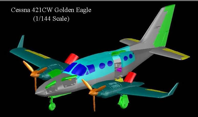
…And in flight with the gear retracted.

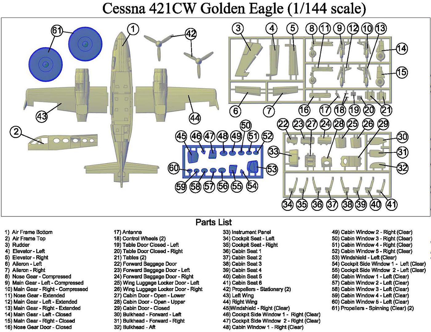
The image below shows the parts diagram for the 421CW.

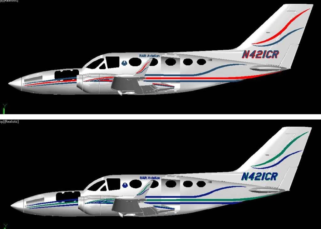
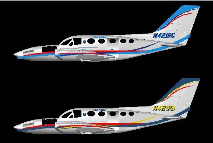
Of course, I had to make decals for it, I couldn’t decide on color schemes, so I did two…

…And was having fun, so I decided to make a second scheme for the 421C too.

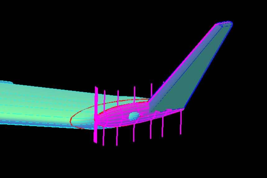
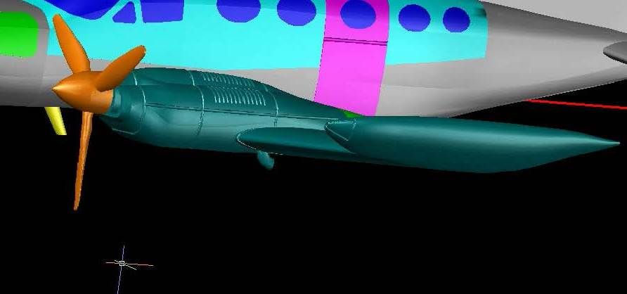
 Converting the 421C to the 421B required adding the wingtip fuel tanks and redesigning the main gear.  Making the wingtip tanks was tricky, as all I had to go on were some marginal 3-views, and a few pictures.  I started by tracing the outline of the tank from the front view with an ellipse, shown in green in the image below.  I figured this would be the fattest point of the tank.  I also traced the top view of the tank using a polyline (also shown in green).  I would have traced the side view, but it is so fuzzy, I couldn't really even tell where it is supposed to be.

With the outlines traced, the next thing I had to do was copy them to the right locations on the wing tip and rotate them into the proper planes.  The tank section was moved so that the bottom of it was at the bottom center of the wing tip.  When I rotated it 90 degrees it was at the right angle with respect to the wing.  The top view outline I aligned so that the widest part was in the center of the wing where the section is the fattest.

This is where it got tricky.  The top view is just that, a top view.  The wing and the tank are at an angle to that plane, so the top view tracing shows the width of the tank, when looking straight down on it, and is not how wide it is, if that makes sense.  When looking straight down on it, the outer and inner points of the initial ellipse lined up almost perfectly with the inner and outer lines of the top view tracing.  That was a good sign, so the next thing I did was copy the ellipse numerous places forward and aft at right angles to the section.  Then using the top view, again looking straight down on the model, I moved the ellipses out so that the most outside points were lined up with the outside tracing line.  I then scaled the ellipses using these outside points until the most inner part of the ellipse matched the inner line.  I then lofted between all of the sections, and discovered the shape was close but some of the sections on the ends were misaligned, so I moved them and re-lofted it.  At this point, I liked the shape, but it was too big so I reduced it 90% and thought it looked better.  I discovered later that I had mis-scaled the plans I based the design on by 10%, thus explaining the tank being over-sized. The image below shows the sections (magenta), after they have been scaled, and moved, that I used to make the tank, which was joined to the wing.


With the tank finished, I etched the wingtip light.


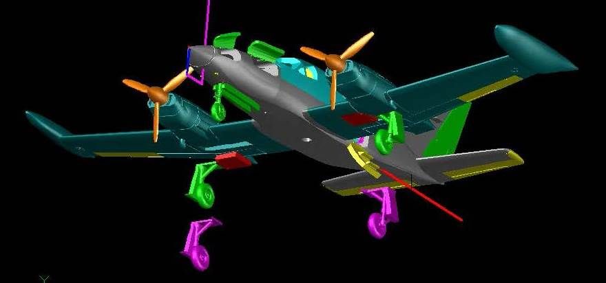
The gear and gear doors also had to be redone, to replace the trailing link landing gear, of the 421C, with the MLG oleo struts used on the 421B.  This essentially meant redoing the entire gear, although I was able to use the wheels.  The good thing is that I only had to do it once, then mirrored it to the other side.  The image below shows the gear, with the compressed gear and door in position on the port side and the remaining gear and doors moved down for a better view of them, and although I changed the design slightly after this image was clipped, you get the idea.

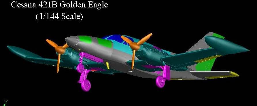
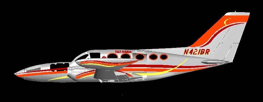
The image below shows the 421B, in flight with the extended gear.

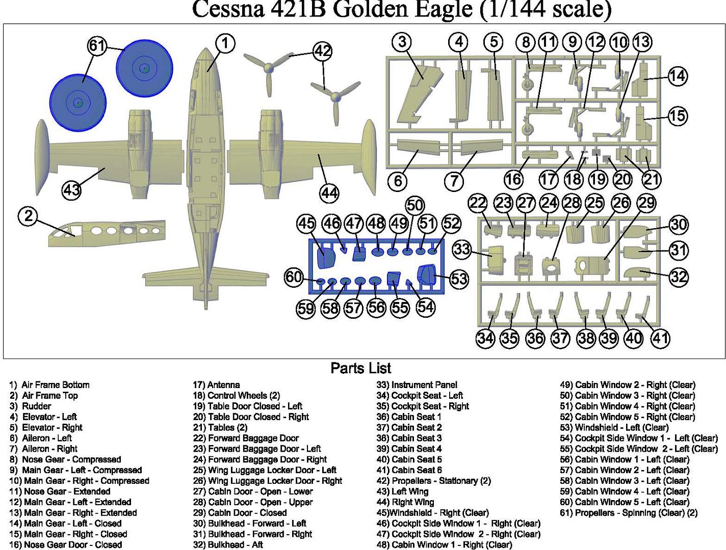
The conversion from the 421C to the 421CW did not require changing the frets, just replacing the wings, but the conversion from the 421C to the 421B, also required modifying the frets, i.e., cutting off the old gear and adding the new gear.  The parts diagram for the 421B is shown below.

And, of course, once again, I had to make decals, for it.  This time I just made one set (so far).


The 421A is in the works…

  • Member since
    March 2012
Posted by Rdutnell on Monday, November 3, 2014 1:15 PM

Update 4 – 11/3/2014

Hi Everyone!

Modifying the 421B to the 421A was the most difficult of the conversions.  I found it interesting that I essentially did the conversions in reverse (except for the 421CW) going from the 421C, to the 421B, and then to the 421A.

The images below show the 421C model (in wire-frame) with the nose forward of the windshield sliced off and deleted.  In the top image the model is superimposed over the plans that I used to design it.  In the lower image the plans laer has been turned off. The magenta polyline shows the outline of the 421A that I traced from a 3-view I found, imported, and scaled to size.  From what I have read, the 421B was 36’ long and the 421A was 33’9” long, a difference of 27”.  The vertical magenta line is 24” (scaled) aft of the nose of the 421B, so the length seems good.  The forward part of the cabin matches well too, but the aft section and tail are completely different. 

In my brief research, I have seen nothing about the aft section being modified, and find it difficult to believe that such a major overhaul of the airframe wouldn’t be associated with a change in type, although I guess it is possible.  Still, you would think that such a significant change would be mentioned somewhere, so, I assumed that the difference is in the drawings, not in the actual airframe, and right or wrong, decided not to alter what I have.  Note also that the wheels of the 421A (magenta circles) are not quite as far down as the gear on the 421B, although they used the same gear.


The image below shows the airframe from the top.  Note that I have completed the new, shorter nose and joined it to the airframe.  The long horizontal red lines represent the wingspan of the 421A.  You can see that it is smaller than the wingspan of the 421B.  The horizontal stabilizers of the 421A (in magenta) are identical to the 421B.  This gives more credence to one or both of the side view drawings being off.  The engines of the 421A (shown in red) are closer to the fuselage than on the 421B. 


The next image shows the wings after I shortened them, which I did by slicing part of the straight sections off of the interior part of the wings between the engine and fuselage, deleting the small bits, moving the wings, and rejoining the remaining parts.  Note that this only reduced the wingspan half of how much it needed to be reduced.  Unfortunately, to make the wingspan any smaller, I would have to alter the exterior part of the wing which would necessitate doing them over, so I decided to live with the slight difference.  Shhhh! Don’t tell anybody and they will never know.


Being (somewhat) satisfied with the airframe and wings, I turned to the gear.  The image below shows the existing 421B gear (both compressed and extended) and the wheel positions of the 421A (magenta).  It appears that the change in height of the two wheels is due to the fact that the forward gear has to be higher to fit in the shorter nose.

I got on a roll at this point and didn’t document the process, but essentially it involved dicing and slicing the gear, airframe, and wings, then putting it all back together correctly.  The images below show the completed gear on the airframe (top) and moved down for easier viewing (bottom).  Note that I again made three versions, closed, compressed and extended.  The closed doors are in red.

The image below shows the completed 421A with the extended nose gear, as if coming in on final approach.


The image below shows the parts diagram for the model.

Of course, no model is complete without decals, so I again prepared a decal sheet.  The image below shows the scheme I designed, roughly based on a picture I found on-line.

The completed decal sheet is shown below.

All of the files for all 4 versions have been sent to C2D.  I will keep you posted on the status.

CHEERS!

JOIN OUR COMMUNITY!

Our community is FREE to join. To participate you must either login or register for an account.

SEARCH FORUMS
FREE NEWSLETTER
By signing up you may also receive reader surveys and occasional special offers. We do not sell, rent or trade our email lists. View our Privacy Policy.