SEARCH FINESCALE.COM

Enter keywords or a search phrase below:

Marvel's Agents of SHIELD AMCS CXD-23 'The Bus'

25549 views
28 replies
1 rating 2 rating 3 rating 4 rating 5 rating
  • Member since
    September 2014
Marvel's Agents of SHIELD AMCS CXD-23 'The Bus'
Posted by Teddz on Tuesday, September 23, 2014 8:44 AM

This whole project is my first ever kitbash (using 2 c-17 kits), and also the very first replica prop my new company is making. This one will be a one-off and will probably stay with me (unless someone makes a really nice offer), but I plan on building another 3 or 4 that will be 'in-flight' like the one on the desk in the show.

After countless hours researching and pouring over the screen caps, I got started...
 
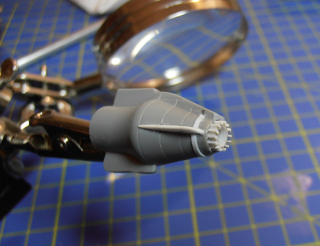
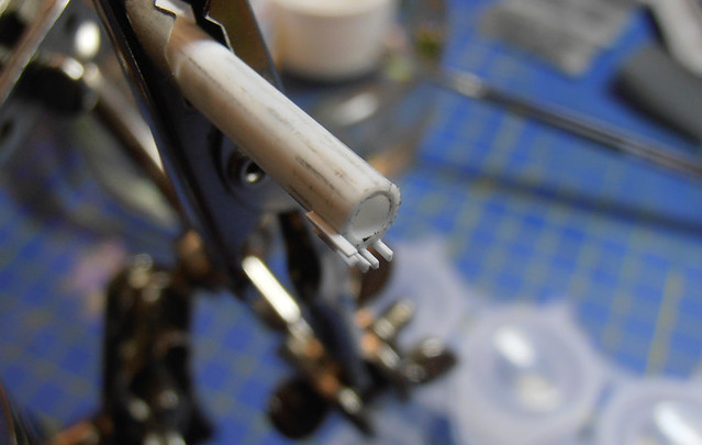
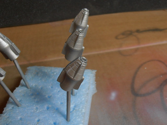
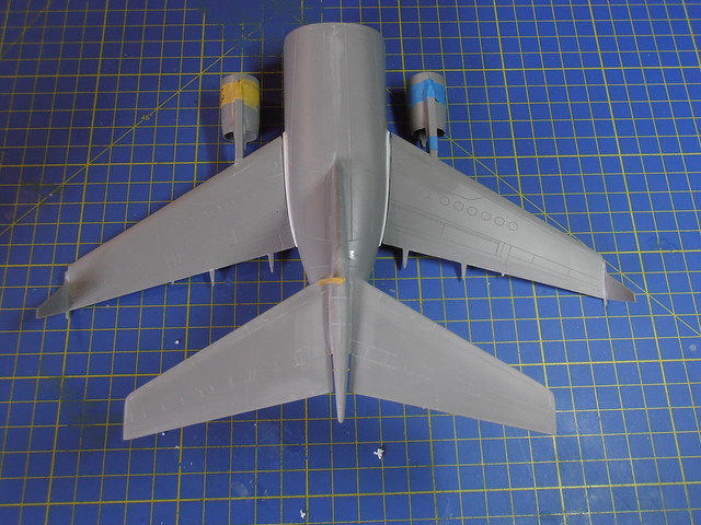
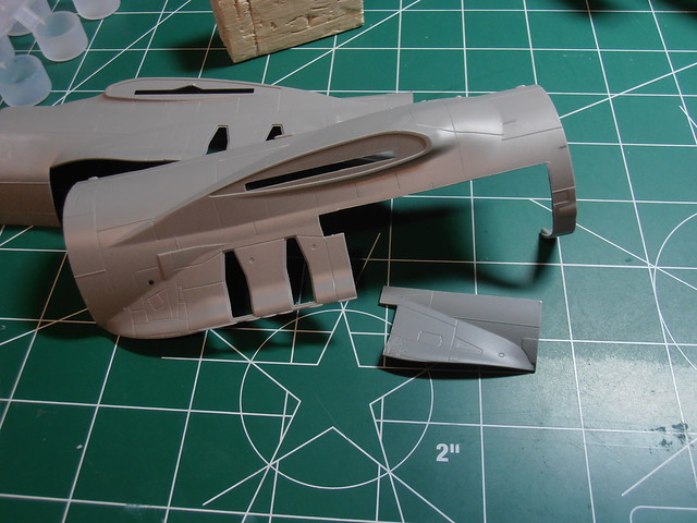
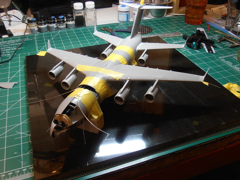
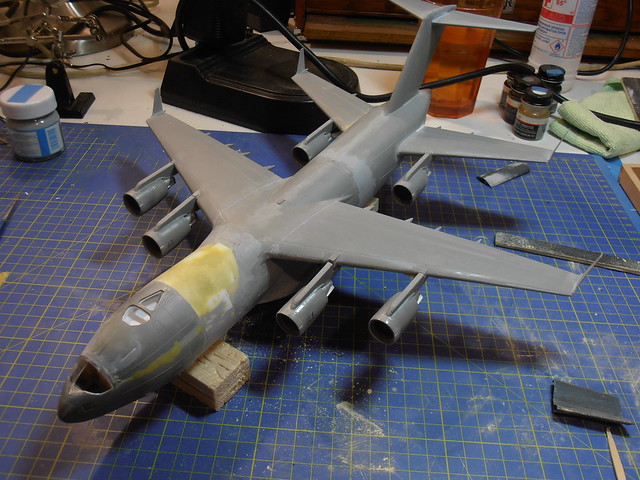
First, I started with the engines. The kit supplied were just all wrong. 18 additional pieces of styrene per engine were added to make it look right.


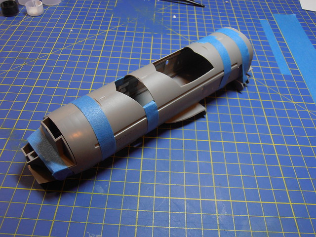
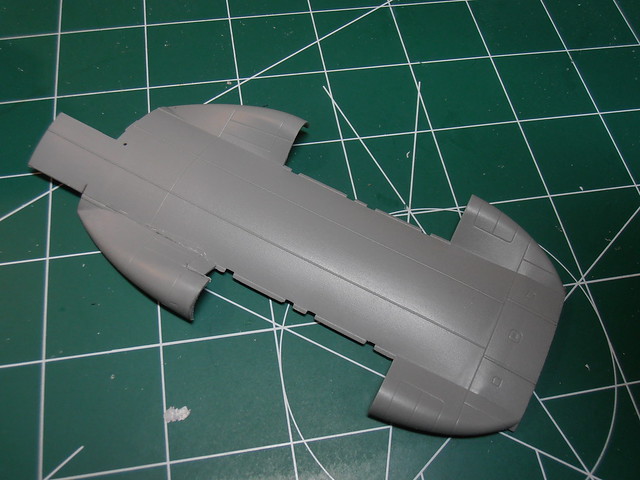
I had to cut and stretch not only the airframe but also the cargo area... Also had to modify the sponson on right side to match the opposite side. The screen aircraft has equal length sponsons.


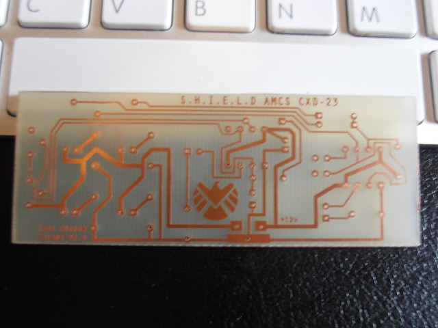
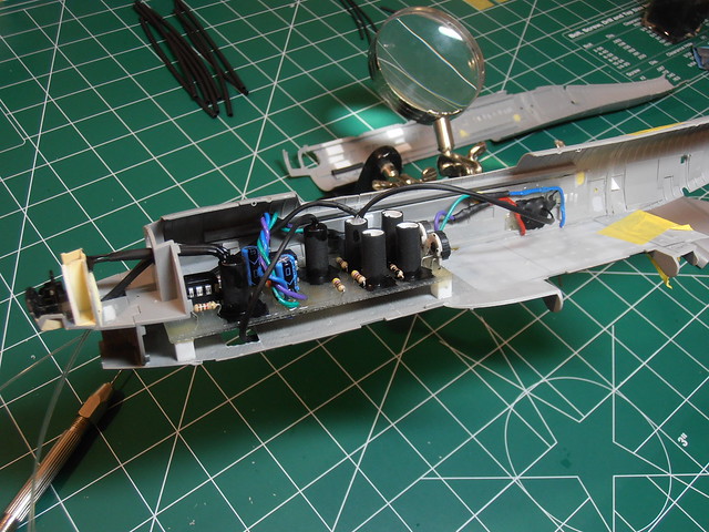
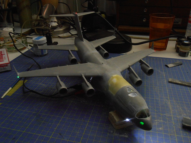
She's getting fiber optic lights, so I needed to fabricate a PCB for the LED's... the board has 1 green LED with a dimmer, 1 strobe, 2 bright white leds and the 2 for the nav lights. It's all activated by a touch-sensitive on switch with a timer that's going to be in the shape of the SHIELD logo on the base. Never did anything like this before.

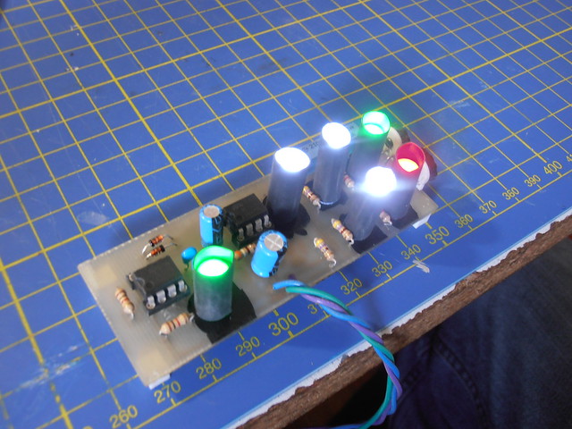
managed to get a pic with the strobe lit up.

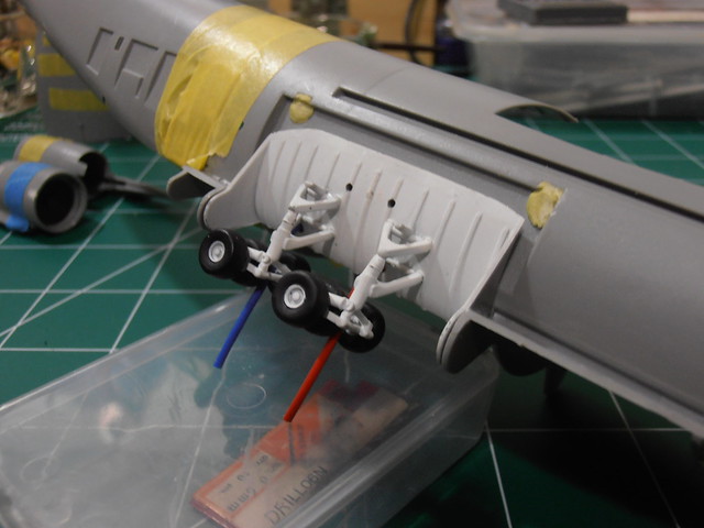
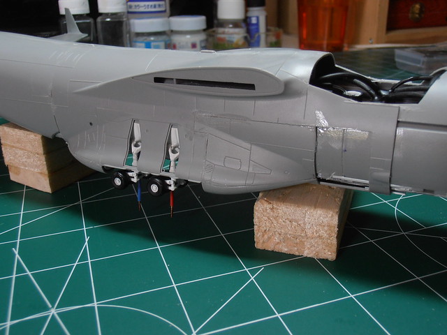
12v power comes via the landing gear. Once set "on the ground" the power wires can't be seen.


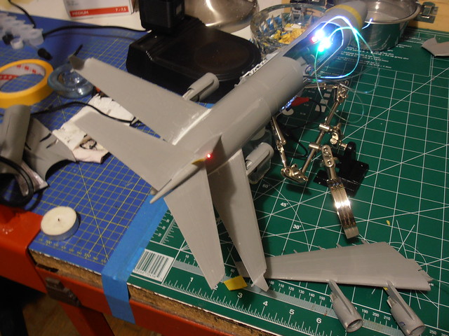
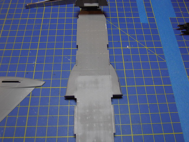
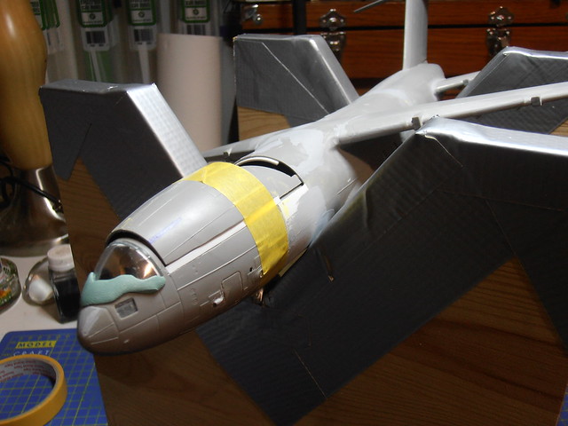
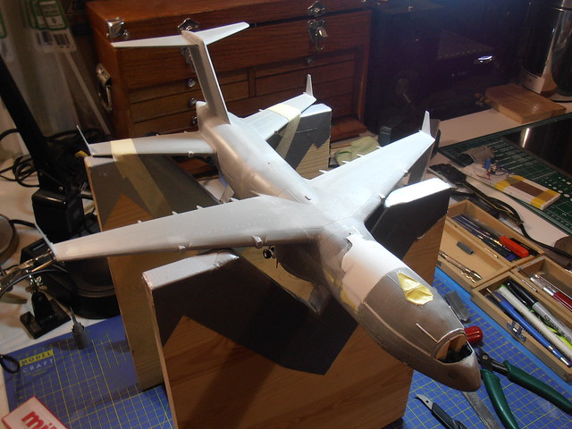
The rear wings on the screen aircraft aren't as far back as they're shown on the blueprint that I had found. In fact, the 'blueprint' is all wrong when compared to the screen aircraft. After some cutting and lots of sanding, they hug the lines of the fuselage nicely. Almost no filler was used in the joint after gluing them on.


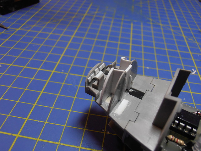
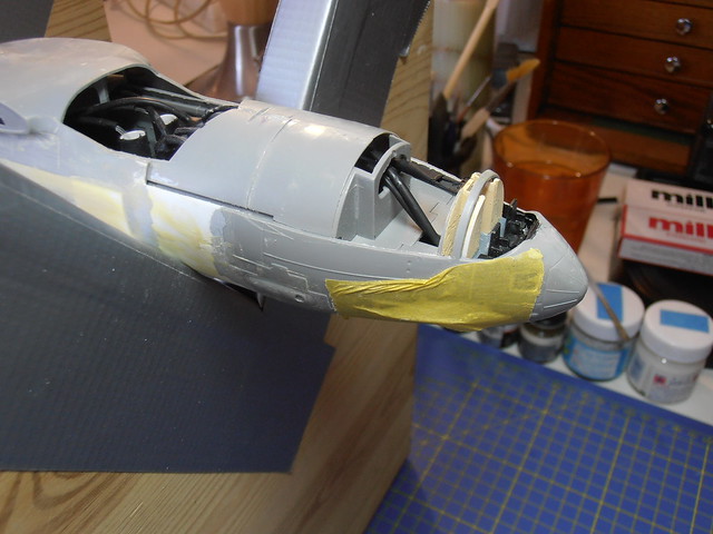
cockpit details... some 'screens' added and the throttle hump in the center. Seats were removed and closets put up. The cockpit door was closed up and now hold the fiber optics.

Just before closing up the cargo area


Modification of the right side sponson to match the other side... Used the recessed panel lines as guides.


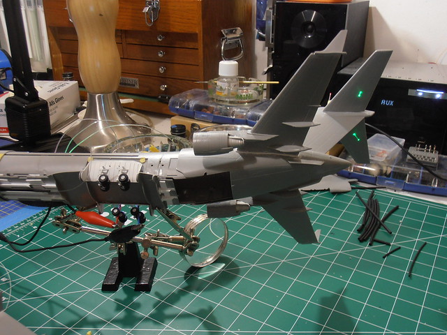
Quick dry-fit to see how it is on the 40cm2 x 1cm thick Black Granite tile that will be part of the base. The base will have a 25mm thick plywood backing and be surrounded by either mahogany, walnut or red oak moldings. 


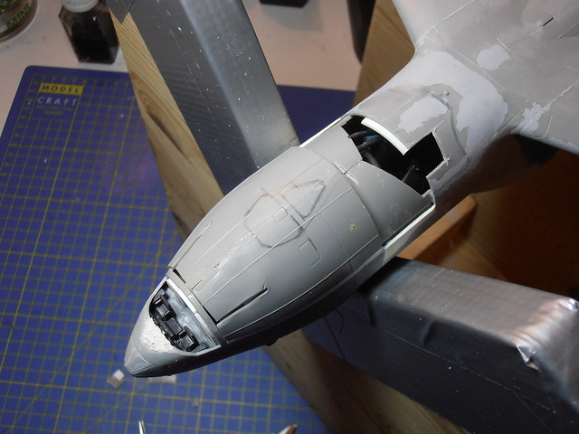
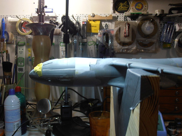
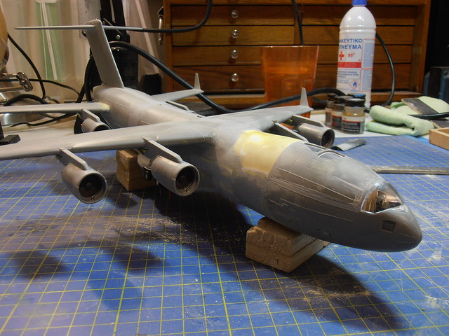
One of the last modifications was the addition of the hump.  I've cut the section away at the panel line and kept the arch for the cockpit glass in place so things get put back where they're supposed to be.


First attempt at getting the height, I glued 2mm styrene strip but it was too much and made it look strange.

The angle was all wrong, so I removed the 2mm and put in 1.4 mm strip. Cut a couple of reliefs into the top and heated them until I got it where I wanted. Looks much nicer. Ugly, but nicer.


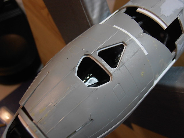
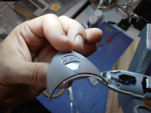
Next on the hump, was the skylight for Coulson's office. This little thing took me all day, literally 8-fun-filled-exiplative-laden hours to complete. I had only one shot to get it right and kept checking and rechecking against the screen caps I had because failure at this point would be very bad (no spare fuselage to cut up). I went very slow when cutting too. That square hole by the wing is an access point so I can drill into the LED and attach the Fiber Optics for the office.

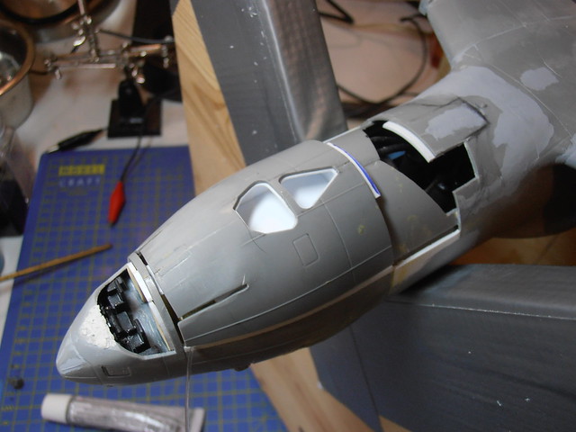
all cut out... Those little diamond files are awesome for stuff like this.

Since it's going to get 'frosted glass' it needs something to keep it in place. Single piece of styrene added to the underside and carefully filed away by hand until it was just right.

Made a box to hide the components inside and also to reflect the fiber optics better. 3 strands of fiber optics are in there and give a nice glow to it.

One of the 3 fiber optic strands in the office.


Now that the office is done and in place, top section attached, time to close it up.

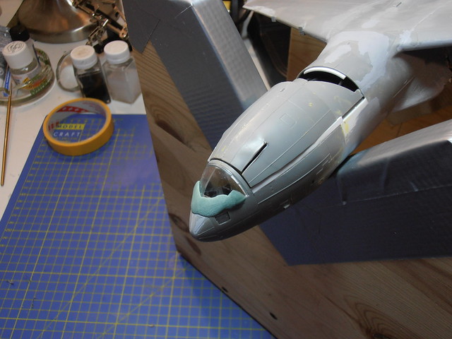
Since I was using a single piece of styrene to close it up, the area of the hump just aft of the office is too flat. Millitput to the rescue!! Those relief cuts and and gaps were filled with styrene strip then smoothed over.


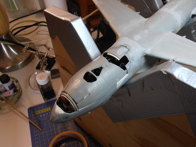
Still needs a bit of work, but it's looking good.

And let's not forget to plug it in as see it all lit up. In all, there are 22 individual points of light inside the aircraft. The cockpit also has Green light, but can't be seen too well yet. Once the clear plastic is painted, it'll show up better.

So that's where she's at now... still scribing & replacing sanded off detail before the first full coat of primer.

Thanks for looking :)

  • Member since
    March 2013
Posted by LonCray on Wednesday, September 24, 2014 8:33 AM

Good googly moogly!  Great conversion!  Looking forward to seeing her all painted up.

  • Member since
    December 2002
  • From: Fort Knox
Posted by Rob Gronovius on Wednesday, September 24, 2014 12:25 PM

Awesome job. The show dragged for me and I stopped watching, then caught the post-Winter Soldier episode, still thought it dragged.

  • Member since
    August 2007
  • From: back country of SO-CAL, at the birth place of Naval Aviation
Posted by DUSTER on Thursday, September 25, 2014 8:57 AM

  WOW great kit bashing and creating

Steve

Building the perfect model---just not quite yet  Confused

  • Member since
    October 2008
  • From: England
Posted by P mitch on Thursday, September 25, 2014 9:36 AM

Amazing work and building your own circuit boards is just showing off!

Phil

"If anybody ever tells you anything about an aeroplane which is so bloody complicated you can't understand it, take it from me: it's all balls." R J Mitchell


  • Member since
    September 2014
Posted by Teddz on Tuesday, September 30, 2014 3:39 PM

Thank you everyone for all your kind words...

I think I'm "done" with the modifications to the 6 engines making them similar to the screen aircraft. They're still wrong, but I'm not about to crack them open now to fix it. Next build will account for this. Each engine required 21 additional pieces of styrene, for a total of 126 very small pieces that cost me my morning coffee a few times to place... They're done, so coffee is flowin again!

I used 1.5mm x 2.5mm styrene strip to make the greeblies on the outer shell of the engines. I set up a jig using some scrap wood, vice on a ball joint holding my dremel with a sanding disc to get the angle consistent for the strip. Once done, I cut them into 13mm sections and stuck them together using tape. Using a jewelers hand vice and file I sanded them into shape.

I feel I should mention I used black magic marker to identify how the material was being removed. It made life easier than trying to tell how it's going when it's all white.

All six "done"... still need some sanding, filling and scribing, but they're looking better...

  • Member since
    September 2014
Posted by Teddz on Sunday, October 5, 2014 7:46 PM

Since the lathe was free today, I used the nice quiet sunday to make the parts for the touch-sensitive on switch that will be on the base. I could have used MDF, but I don't have any and quite frankly seems cheap. I had a leftover piece of Billet T4 Aluminum that was perfect. A lot of material went to waste, but it was this or sit around forever again and take up space.

On the milling machine getting the notches... I ended up breaking a drill bit quite a ways in and had to mill it down to clear it. Luckily, I have just enough material to make it work.

Here's the housing cup with the notches and top cut off. Tomorrow I'll drill and tap the holes for the screws, finalize the machining on the bottom section of the cup and cut a lip into it for the acrylic. I'm also going to pick up some 4mm T4 Aluminum plate to cut the logo pieces. This whole unit will act as a touch sensitive on switch for the Bus. It will also have lights of it's own and look just as cool as the aircraft.

  • Member since
    May 2012
Posted by Philbouq on Monday, October 6, 2014 2:21 PM

Never saw that the SHIELD symbol was so geometrically designed.

Thanks also for is too Teddz !

  • Member since
    September 2014
Posted by Teddz on Monday, October 6, 2014 4:07 PM

The logo laid out on the 4mm plate aluminum.

After several hours of carefully filing down by hand, the aluminum bits, I put them in their place... looking good!! Now I just have to bevel the edges of the logo bits.

  • Member since
    October 2007
  • From: Scotland
Posted by Milairjunkie on Tuesday, October 7, 2014 3:55 AM

Got an itch - scratch it!

Very impressive work & I look forward to seeing more Yes

  • Member since
    September 2014
Posted by Teddz on Friday, October 10, 2014 10:40 AM

I finished off the top part of the on switch. :)

Here's the logo after beveling all the pieces.

Bonded to the hand-cut acrylic and placed into the bottom portion of the switch.

Here's the top portion all done with the ring.

And what I call the top-down official shot...

Now I have to finish off the electronics, make the circuit boards, put it all together and test to see it light up before I test to see it and the bus light up together. Then I can figure out how long I want them to stay on by how big of a capacitor bank I build into the base.

  • Member since
    October 2014
Posted by PaulMNewitt on Saturday, October 18, 2014 11:01 PM

I built the original model for the show (MAOS) over a year ago (and was mentioned in the "Declassified: The Making of MAOS" book).  Your skylights for Coulson's office seem a bit large; and the original has lighted windows on both sides. There are Red/Green NAV lights on both the main wings and rear winglets as seen on the show, and no lights seen on the underside of the top tail fins (as on a C-17), nor on the nose. This is a pretty good effort, and you found all the tough spots that needed work. I had a week to make mine for the production, due to the expected time crunch.

  • Member since
    October 2014
Posted by PaulMNewitt on Sunday, October 19, 2014 7:39 PM

I built the BUS model, as seen in Coulson's office on MAOS.  Photos of the prop have appeared in "Declassified: Marvel's Agents of SHIELD Season ONE" book.  Photos to follow.

  • Member since
    September 2014
Posted by Teddz on Tuesday, October 21, 2014 3:17 AM

I knew eventually I'd find the person who made Coulson's desk model. Awesome work Paul. Only took you a week? WOW. I've been at this for months... but then again, this is my first kit-bash in my many years of building models and I'm taking it kinda slow so as not to mess it up. What kit(s) did you use for your model?

I thought about putting nav lights on the winglets, but since I was going for more show accurate, those nav lights were tossed and modeled after what I saw on screen. As for the lighted windows on both sides, I thought about it, but decided to just scribe/paint on the windows for now. I even started to build the lab and staircase for the cargo area, but with the addition of the LED board and 23 fiber optic strands, there was just no room... not to mention making the overhead bulkheads in the lab by hand was next to impossible at that scale. Next attempt will have a CNC Laser behind it to help out.

One area I did find a bit bothersome (mainly because I wanted to include the Lab) was the aft section. On the Bus, from the lab doors to the hinge point of the cargo bay door, there's room to move around and even have a staircase, whereas while building the model, no room. In comparing images, the cargo door is in the same location it should be normally, but it shouldn't be... It took a minute to figure it out and with the cargo door closed, it looks fine.

I have a resin 1/72 Anigrand C-17 sitting on the shelf that's going to be the next Bus with a LOT more detail and possibly moving control surfaces.

  • Member since
    October 2014
Posted by PaulMNewitt on Tuesday, October 21, 2014 2:19 PM

You're doing a great job, Teddz!  As with most TV/Movie productions, the interiors don't match up with the exterior (i.e. Disney's Nautilus).  I used two of the Revell C-17A Globemaster III kits.  I can't say, but I did build more than one BUS, and I was scouring all the kits I could find locally!!  During production, they decided that the whole plane is larger than a C-17 overall, to fit everything into it.  I admire your enthusiasm, and ideas for your project (and I'm envious of your machined base! How cool!).  I'll forward this URL to the production team at MAOS to show them what you've done!!  Keep a shape eye in future episodes…as there might be more prop planes to see… (and by the way, I wrote the Star Fleet Assembly Manuals for building and lighting the Trek kits, so I know how hard it is to shoehorn electronics into models!!  You can see my work on my Facebook page under "Paul M. Newitt".

  • Member since
    September 2014
Posted by Teddz on Tuesday, October 21, 2014 5:37 PM

The logo works :)

  • Member since
    September 2014
Posted by Teddz on Wednesday, October 22, 2014 1:54 PM

Thanks for the kind words Paul.

Yea, I figured early on that it was like the tents from a Bugs Bunny cartoon that are bigger on the inside than the outside. I had actually cut the aft section and extended it just enough to account for the space shown. The only thing that would be different would be where the cargo door hinges, but since it was in a closed position, it looks right.

I also used 2 of the C-17 Globemaster RAF/Qatar kits from Revell Germany... just thought you may have gone with a resin kit since you built it so quick.

That would be cool... Let production know that they are directly responsible for me making a touch-sensitive on switch instead of just a regular slider switch to turn the lights on in the Bus... Them and all that techy stuff they're doing on the show. I had to learn it all from zero when I started building the Bus. I went to school for Graphic Design, not electrical engineering...

I haven't read the manuals, but know of them from friends that are DEEEEEP into it. I'm just getting the hang of making my own circuit boards, lighting up my models with LED's/Fiber Optics and working with really small components (ex. surface-mount resistors that are 1.6mm x 0.8mm) that will help me light up more of my builds using less space.  

  • Member since
    October 2014
Posted by IronMike75 on Wednesday, October 22, 2014 2:58 PM

That looks awesome!!

  • Member since
    September 2014
Posted by Teddz on Saturday, October 25, 2014 9:24 AM

Got the M2 stainless steel allen head machine screws and a set of taps so I buttoned up the logo switch. All that it needs now is to be installed in the base and wired up to await the addition of the Bus. Looks official now.

  • Member since
    January 2003
  • From: Washington, DC
Posted by TomZ2 on Thursday, November 6, 2014 5:39 PM

NICE !!!

Occasional factual, grammatical, or spelling variations are inherent to this thesis and should not be considered as defects, as they enhance the individuality and character of this document.

  • Member since
    October 2004
  • From: NE Oklahoma
Posted by Allen109 on Saturday, November 22, 2014 4:49 PM

Very nice!

  • Member since
    March 2015
Posted by MandoMan531 on Saturday, March 7, 2015 2:00 PM

Nice! I've been sitting on two C17 kits wanting to attempt this but I haven't to ally figured out my game plan for extending everything...

  • Member since
    March 2015
Posted by Bridgetdaddy on Friday, April 3, 2015 5:28 AM
Wow! Amazing work.
  • Member since
    September 2014
Posted by Teddz on Friday, April 3, 2015 2:01 PM

Thanks for the kind words everyone...

@mandoman531, If you're looking to build the Bus and cant figure out where I cut it up in the pics, drop me a msg with what you're trying to do and I'll be more than happy to help you out.

  • Member since
    September 2014
Posted by Teddz on Sunday, July 19, 2015 7:31 PM

Not much doing on the 1/144 Bus since I was getting these together... Had an issue with the circuit boards I was making and they wouldn't work right and it consumed me until I figured it out. Finally figured it out and managed to get the first few together and out. Big Smile

They're stand-alone versions of the touch sensitive on switch I made for my Bus display. I made both SHIELD and HYDRA versions. Made them larger (4.5" instead of 3.5"). Same billet aluminum construction (only with a deeper bottom cup), M2 Stainless steel allen head screws, frosted acrylic and all embedded in a wooden base. 9V operation with an expandable capacitor bank (initially set up with 1x 1000uf capacitor good for 35 seconds of ON time but can be expanded to 4x 1000uf or 1x 10000uf capacitor) and can still be hooked up to something else to trigger it on.

SHIELD

HYDRA

More Bus news coming soon...

  • Member since
    August 2007
  • From: back country of SO-CAL, at the birth place of Naval Aviation
Posted by DUSTER on Monday, July 20, 2015 11:43 PM

Just WOW from me

Steve

Building the perfect model---just not quite yet  Confused

  • Member since
    September 2014
Posted by Teddz on Tuesday, September 1, 2015 4:49 AM

Look what came in the mail yesterday...

Anigrand 1/72 C-17 Globemaster III resin kit... The new Big Bus is coming.

This thing is huge!

  • Member since
    June 2010
  • From: Australia
Posted by OctaneOrange on Friday, September 4, 2015 6:00 PM
This is the second time i've come in here to look at your bus, it's still amazing work. waiting for next update (or the big reveal)
  • Member since
    August 2012
Posted by revenge_artist1988 on Monday, November 30, 2015 8:22 PM

Are you selling the stand alone light up shield one as I would like one for my personal bus build

JOIN OUR COMMUNITY!

Our community is FREE to join. To participate you must either login or register for an account.

SEARCH FORUMS
FREE NEWSLETTER
By signing up you may also receive reader surveys and occasional special offers. We do not sell, rent or trade our email lists. View our Privacy Policy.