SEARCH FINESCALE.COM

Enter keywords or a search phrase below:

Trumpeter 1/350 HMS Dreadnought 1907

34824 views
113 replies
1 rating 2 rating 3 rating 4 rating 5 rating
  • Member since
    July 2004
  • From: Texas
Posted by wbill76 on Wednesday, August 20, 2014 5:39 PM

They say the devil's in the details...well today the devil tasked me with working on the searchlights. Since a few of these go on the super deck and the boat deck, I decided it was as good a time as any to tackle them all and get them ready for painting along with the other details. The kit supplies you with 14 but only 13 are needed. I went ahead and prepped all 14 just to have a spare since the Eduard PE set includes 14 bezels as well.

First up was drilling out the faces of the lights. This was done with a pin vise by hand while the lights were still on the sprues. This made it much easier to handle them and control the drill bit vs. trying to do it with them off the sprues.

Once that was taken care of, they were removed from the sprues and cleaned up where needed. The Eduard bezel faces were added using liquid glue and a spit-moistened toothpick to help in the pick-up-and-placement of each little bezel.

Once painted, these will get further detailed for the reflective surfaces and what not.

  • Member since
    July 2010
  • From: Tempe AZ
Posted by docidle on Wednesday, August 20, 2014 7:33 PM

Beautiful work Bill.

Steve


  • Member since
    July 2004
  • From: Texas
Posted by wbill76 on Wednesday, August 20, 2014 7:42 PM

Thanks Steve! One more step out of the way in the detail department.Wink

  • Member since
    July 2004
  • From: Texas
Posted by wbill76 on Friday, August 22, 2014 4:24 PM

Lots of progress to report today. First up were the baffles and screens for the funnels. Trumpeter provides these as multiple PE parts (5 different parts for each funnel) and they are all extremely fine/fragile. The internal baffles are probably the most fragile as they require a lot of bends but the part itself isn't that sturdy to begin with. One thing that Trumpeter does that I like is they provide their PE with a laminated adhesive sheet...if you only peel off the top sheet, the bottom sheet remains stuck to the back and you can use that to your advantage for parts like this. By only freeing one leg at a time and bending it up into place, it was possible to get all the legs into position where needed...then one last cut to free the baffle from the fret.

Then the real fun begins...I opted to glue the baffles into place first inside the funnel cap using liquid glue, then added the outside ring, and finally the top portion of the screen. The funnel tops are only dry fit for now to make it easier to paint them separately from the funnel stacks as masking due to all the PE is clearly not an option.

After studying the rigging diagrams, I decided to add some rings for the signal flag lines that will be rigged later on. I used the fine copper chain that came with the Hunter deck and clipped out 12 links, cut them in half with fine wire cutters, and glued them in place with CA.

Then it was finally time for some more paint to fly...I primed everything with Flat Black since I needed to spray some anyway for the funnel tops. The turret tops were sprayed with Panzer Gray and everything else got the same custom gray mix that was applied to the hull. In order to paint the 12 pdrs, I stuck them in small blobs of blue tack putty and then stuck the putty to the masking tape so I could paint them more easily since they have mount pins on their bases.

That will get a chance to cure up and this weekend will see more detail work in terms of getting the gear installed on the first super deck level so I can secure the boat deck and continue to work my way up in the superstructure.

  • Member since
    September 2013
  • From: San Antonio, Texas
Posted by Marcus McBean on Friday, August 22, 2014 9:10 PM

Wish I thought of leaving on the plastic film when I did the baffles.  Remove them when I cleaned the PE in solvent and then in vinegar to  rough them up for painting.

You are making great progress, I really like you idea of the tie downs for the signaling flags.  You won't mind if I use it on my dreadnought.

Marcus

  • Member since
    December 2010
  • From: Salem, Oregon
Posted by 1943Mike on Saturday, August 23, 2014 12:26 AM

I couldn't manipulate the PE for the baffles on the funnels into the proper configuration to save my life! My hat's off to you for your skill in working with the brass and for the helpful tip about leaving on one side of the plastic protector on the metal while working with it.

I am very, very impressed with how neat and tidy your work is!

I think any posts of images of my WIP will now be taken from 5 feet away Big Smile.

Mike

Mike

"Le temps est un grand maître, mais malheureusement, il tue tous ses élèves."

Hector Berlioz

  • Member since
    July 2004
  • From: Texas
Posted by wbill76 on Saturday, August 23, 2014 9:26 AM

Thanks Marcus! No problem at all with you using the tie-down idea...that's the point of build logs like this after all, the sharing of info and techniques that may prove helpful to others even if it shows what NOT to do! Wink

Mike

appreciate the comments as well. Don't stress over your own build...working with PE like this is not something I particularly enjoy but is a necessary evil when dealing with details in this scale...most of the time it works out, sometimes not. Fortunately there have been others who have built the kit and noted, like Marcus, how fragile the PE parts were in this case so I had some forewarning to encourage me to think just a little bit more about how to try to attempt it! Beer
  • Member since
    July 2004
  • From: Texas
Posted by wbill76 on Saturday, August 23, 2014 4:43 PM

Building on the paint progress from yesterday, today's efforts were all in the detail department. Turrets received their 12 pdrs along with the Eduard platforms and guard rails. The 12 pdr mounts as-is were all pointing downward, so some gentle pressure on the breech portion of the gun 'elevated' them so they would sit at a level height once installed into the platforms. Took a little trial-and-error but eventually I got all 10 sitting at pretty close to the same height. The 12 pdrs got a little extra detailing in the form of some Model Master Non-Buffing Metalizer Brass applied to their breeches.

The funnels got their caps permanently installed and the signal flag deck area and aft searchlight platform were painted with Panzer Gray to detail the crew walk areas. Same thing for the aft conning tower's fire direction platform. I'll wait to install some railings for it until I'm ready to finally install it in place to avoid any possible damage or complications.

Front portion of the boat deck received its wood decking as well as a permanent install. This is much easier to handle with the deck 'loose' vs. fixed and today was as good a time as any to check that off the list.

The boat deck levels are still dry fit only at this point as I need to work on the super deck level details next. Doesn't hurt to do a quick check though to make sure everything's still playing nice with each other.

  • Member since
    September 2013
  • From: San Antonio, Texas
Posted by Marcus McBean on Saturday, August 23, 2014 8:09 PM

Bill,

Making great progress, really like the bass added to the 12pdrs.  I see your model has the bollards on the bow portside, mind are missing on my model, will have to fabicate a couple.

Marcus

  • Member since
    July 2010
  • From: Tempe AZ
Posted by docidle on Sunday, August 24, 2014 1:05 AM

Bill,

Your Dreadnought is looking awesome!  She is coming together rather nicely to say the least.  I really like your idea of leaving one of the plastic wraps on to help keep things together for the baffles.

Are you going to drill holes in the stacks as well as the various deck locations for the tie downs?  I did that as soon as I put the stacks together and drilled holes on the decks.  Of course I used the Kagero  book and line drawing for the tie down locations as the Trumpeter instructions did not show anything.  Also, I am not sure how much detail are you going to put in the rigging.

As I said earlier, very nice work.  I have nothing to post lately as I have been juggling family commitments and have not had a chance to even sit at my work desk.

Steve


  • Member since
    July 2004
  • From: Texas
Posted by wbill76 on Sunday, August 24, 2014 10:31 AM

Marcus

, thanks for the comments! That's odd that your hull is missing that port bollard pair, maybe just a 'short shot' in the molding process? Shouldn't be too hard to fabricate a couple if you've got suitable rod stock or similar to work with.

Steve

Thanks as well! I'm having some fun working with it even if the details are tiny...progress is still progress! As for the funnel stay lines, it's on the list of things still to do but haven't gotten to them yet. Like you, I've been looking at the Kagero positions and figuring out where they go and when to add them...I had been waiting for an order of EZ Line to come in and now that I have it, I can do some quick tests as well.

Since the lines for the fore funnel require interaction with the admiral's walk, I haven't done anything there yet. The aft funnel's lines all interact with the boat deck and searchlight platform to different degrees, so have to figure that out so I don't cause any issues with how the boats install and will add those holes before I permanently attach that to the superdeck. My plan is to leave the funnels loose for as long as possible to facilitate all the necessary puzzle piecing that has to happen in those areas.  Sorry to hear that RL is keeping you away from your work desk and hope you can get back at it sooner rather than later! Beer

  • Member since
    July 2004
  • From: Texas
Posted by wbill76 on Sunday, August 24, 2014 7:43 PM

I started in on the super deck's interior details today and immediately encountered an issue when it came to installing the 12 pdrs. The added fractional millimeter of the wood deck is a partial contributing factor but the bulk of the issue had to do with the bases of the guns and how they needed to mount into the various slots in the super deck structure. The mount pins work great for open spaces like the turret tops or the open decks...but when they have to fit into the tight spaces like most of the superdeck's openings, it was virtually impossible to get them into position.

I ended up removing all of the mount pins and sanding the bottoms of the bases smooth and using CA gel to mount the guns into position over the mount holes instead. It's also worth noting that while the guns themselves are installed in Step 16, the exterior port covers that also need to line up with the gun barrels aren't dealt with until Step 26 and they have to fit just so together to look right. So much flipping back and forth in the instructions was called for as I worked on getting the guns installed as a result and it's a slow and tedious process as the panels have only a very tiny contact surface for gluing. I suppose you could also opt to pose the covers in the down position and have less hassle that way but it definitely doesn't look the same.

I also hunted through the instructions and added all the little exterior parts like the hose reels, ladders, and the walkways for the wing turrets. I also discovered that the rectangular hatch covers D29 are meant to sit right up against the aft funnel's base, so they have to sit just right for there not to be any interference. I glued those in place first and then left the funnel sitting in position until the glue had set to make sure there wouldn't be any issues later on in that area.

Next up will be getting the boat deck components in place and continuing the upward climb on the superstructure components. I should also note that the Wood Hunter provided coal scuttle PE inserts are a perfect fit for the openings in the deck vs. the Trumpeter items which are too small, I tried out a couple that were needed for the super deck and they fit like a glove.

  • Member since
    July 2004
  • From: Texas
Posted by wbill76 on Monday, August 25, 2014 8:10 PM

Building on yesterday's efforts, I permanently installed the boat deck levels in place over the super deck. Funnels were also permanently installed after I used a #80 finger drill to create mount points for the bracing wires. Wires were added using the Fine grade of black EZ Line and CA. The final pair of bracing wires for the fore funnel will be added once the mast tripod is in place since they connect to the legs vs. down to the deck itself.

There's still more detail work for the boat deck level including the aft searchlights and railings, the pair of 12 pdrs on either side of the conning tower, and the admiral's walk left to do before I can move on up to the bridge deck.

  • Member since
    September 2013
  • From: San Antonio, Texas
Posted by Marcus McBean on Monday, August 25, 2014 9:08 PM

Bill,

You are making great progress, she is really shaping up nicely.  Makes me want to stop work on the other ship and pick this one back up.  

I am not being picky, but is the EZ-Line on the smaller funnels bowled out or loose on the starboard side or is it just the photo?  I haven't glue any pieces in place yet, should I be worried about a place to anchor the EZ-Line to the deck when installing this funnel?

Marcus

  • Member since
    August 2007
  • From: back country of SO-CAL, at the birth place of Naval Aviation
Posted by DUSTER on Monday, August 25, 2014 11:34 PM

  Great work to date, Bill

Steve

Building the perfect model---just not quite yet  Confused

  • Member since
    July 2004
  • From: Texas
Posted by wbill76 on Tuesday, August 26, 2014 9:10 AM

Marcus

, Thanks for the comments as always! Sorry to be a source of temptation but that's the ship's fault itself, not mine! Wink What you're seeing on the starboard funnel lines is a trick of the angle/camera I think, on the actual model there's no bowing or slack in the lines there. You do need to do some test fits with the admiral's walk to make sure you get the placement just so for the bracing lines to avoid any issues there IMHO.

Steve

, Thanks as well, glad to have you along for the ride! Beer
  • Member since
    September 2013
  • From: San Antonio, Texas
Posted by Marcus McBean on Tuesday, August 26, 2014 10:12 AM

Bill,

Thanks for the feedback.  

Marcus

  • Member since
    July 2004
  • From: Texas
Posted by wbill76 on Tuesday, August 26, 2014 10:34 AM

My pleasure Marcus! I spent a long time staring at the different photos in the Kagero 3D book to try to figure it out since there's a lot of clutter in that area between the bridge, the funnel, the searchlights/admiral's walk, etc. Wasn't even sure there was enough room available to make it all work but finally hit on the right combo/solution. Definitely a busy space! Wink

  • Member since
    July 2004
  • From: Texas
Posted by wbill76 on Wednesday, August 27, 2014 5:03 PM

Made some more progress on the boat deck level. The next element that needed attention was the admiral's walk. I immediately encountered an issue with its fit in relation to the admiral's day cabin and the little box on the other side of it. I'm not sure if this was a combination of using the Eduard replacement for the cabin, a fit issue with the kit part, or some combination/variation of the two. Regardless, I needed to modify the walk by cutting a notch into it so it could clear the box, part B6, which the instructions have you install in Step 22 prior to the walk going in. I also added the side sponsons (B8/B11) to the walk instead of installing them directly to the superstructure sides as I wanted to sure they would fit flush with the walk and not cause issues. Last but not least, I also added the supports, F23, that the instructions would have you install independently in Step 26. That's not a good idea as they have to attach at an angle and getting that right is pretty difficult without using the walk itself to ensure they sit correctly.  

While the walk supports were setting up, I added the PE access ladders from the super deck up to the boat deck and worked on the aft searchlight platform as well. I found an error in the Eduard railing PE instructions, the correct railing for this area is #12, not #4. #4 gets used on the small searchlight platform on the main mast and is too small to go in this area, so a small note for anyone looking to use that set! I used the small section of railing that I clipped off from the fire direction control platform earlier as the back railing section for this platform, installed the front railing, then added the pair of searchlights to complete the aft portion.

Then the real fun began in terms of the railings for the admiral's walk because of all the complex curves involved with it. I opted for the Eduard rails instead of the Trumpeter railings as the Eduard railings have the correct lower height vs. the Trumpeter railings which are all the same standard height type and the Eduard rails have the added bonus, at least for the inner rail, of having etched bend lines to aid with the shaping of some of the key areas around the searchlights. I added the inner railing first, then added the 4 search lights, then the outer rail came last.  The forward pair of 12 pdrs rounded things out as well.

Next up will be working on the bridge components so I can get them integrated in fully in with the rest of the superstructure.

  • Member since
    July 2004
  • From: Texas
Posted by wbill76 on Saturday, August 30, 2014 10:22 AM

Assembling the two-level components of the bridge deck is a delicate operation that requires a lot of patience, mostly due to the fact of the way its supported relative to the boat deck. I decided the best way to tackle it was to install all the support legs first on the underside of the platform and use the conning tower and the openings in the wood deck to ensure everything aligned properly and then let it sit overnight so the glue could set thoroughly before moving ahead. Before doing that, I also made some minor adjustments so I could use the Eduard bridge house components instead of the kit-supplied parts. The notches in the platform were filled with putty and a combination of the little tabs cut free from the kit part where needed and then the brass house installed with CA gel. After all the legs had set up, I cut the cross braces from the Eduard support legs (which are too 'spindly' IMHO to be used by themselves) and attached those to the styrene legs to add a little more detail.

Out came the airbrush for some quick paint work and then the real work of assembling the two levels together began. The first level received its wood decking and then the Eduard external bridge face and railing were installed. The searchlights and compass stand were added to complete the first level.  

Moving up to the 2nd level, it too received its decking and was glued in position over the bridge house. Compass stand and other details were installed prior to the railing to make life a little easier there. The chart table is extremely delicate as Trumpeter provides it as a PE part and the legs aren't very sturdy, so great care is needed there. The railing for this area has to take on a lot of complex bends/shapes, most of which the Eduard rail has pre-etched to help with, but it's still a delicate dance. I bent it into shape first, brush painted it by hand, then installed it in place. Last little piece of the puzzle was the Eduard-supplied access ladder to the upper deck.

Time for the moment of truth, the whole module was installed in place, integrating with the conning tower and boat deck below.

Rounding things out, the Eduard tall access ladder was added to the rear of the bridge structure.

Next up will start work on the masts.

  • Member since
    June 2013
Posted by RobGroot4 on Sunday, August 31, 2014 3:50 AM

Wow.  This whole thing is amazing, but I have no idea how you managed that bridge!  I know some folks aren't fans of wood decks, but I think it really adds something.  This is a beautiful build.

Groot

"Firing flares while dumping fuel may ruin your day" SH-60B NATOPS

  • Member since
    July 2004
  • From: Texas
Posted by wbill76 on Sunday, August 31, 2014 10:10 AM

Thanks Groot! The bridge is an exercise in patience for sure...just have to approach it very carefully and try not to breathe too hard in the process! Big Smile Appreciate the comments, this is the first time I've used a wood deck on a build and I'm impressed with it so far.

  • Member since
    May 2004
  • From: Mount Bretherton Model Aircraft Observatory
Posted by f8sader on Sunday, August 31, 2014 10:15 AM

B-e-a-u-t-i-f-u-l!  

Lon-ski

  • Member since
    July 2004
  • From: Texas
Posted by wbill76 on Sunday, August 31, 2014 11:29 AM

Thanks Lon-ski! Wink Beer

  • Member since
    December 2010
  • From: Salem, Oregon
Posted by 1943Mike on Sunday, August 31, 2014 1:52 PM

Bill,

As others have said, your work is outstanding!

I'm just so happy that you and Steve are so far ahead of me (I haven't worked on my 1915 version for a week or so - other things to do) that I'm able to see - thanks to your documenting it in this WIP - what the problems and tricky steps are in assembling this kit.

Your work is inspiring and this WIP will be reviewed by me several times before going forward.

Mike


Mike

"Le temps est un grand maître, mais malheureusement, il tue tous ses élèves."

Hector Berlioz

  • Member since
    July 2004
  • From: Texas
Posted by wbill76 on Sunday, August 31, 2014 3:49 PM

Thanks Mike! I'm glad to hear that the build is helping you 'see ahead' for your own project and hope it will help you have a smoother result with your 1915 version! Forewarned is forearmed as they say! Wink

  • Member since
    July 2004
  • From: Texas
Posted by wbill76 on Sunday, August 31, 2014 4:21 PM

I started in on the masts with the foundation of the tripod elements needing attention first. I left off the coaling derrick arm to allow more flexibility in its positioning for later and also to keep it out of the way of trying to install its host leg into position. Trumpeter designed it with a notch near the base that interacts with the boat deck level to install it in the correct position and having the derrick in place would make that much more frustrating than it should be. I airbrushed all three legs after adding in the little platforms to the two front legs and the searchlight platform to the rear leg. All three legs were installed into the super deck and then aligned where they all meet at the top. I left off the little PE support piece, PE33A, for the searchlight platform's underside until after things had set on the three legs to avoid the possibility of it getting knocked loose and lost to the carpet monster.

One detail that I noticed in the Kagero 3D book that was missing were the three triangular braces between the legs, so I used some 0.6mm styrene rod to recreate those. The front brace went in first, followed by the PE ladders for the little elevated platforms, then the rear braces were added. I also added the last two funnel stay lines that connected to the tripod legs to round things out there.

Once all that had set up, I hand painted the braces and added the searchlight and railing to the platform. The derrick came next and I had to decide whether to position it as Trumpeter wanted it or how the Kagero book shows it in the 'stowed' position. The Kagero position would complicate a lot of things including the aft conning tower, the way the signal flag lines would be rigged, and also possibly interfere with the boats...so I decided simpler is best and put it in the Trumpeter designed angle. May not be 100% accurate but it's something I can live with.

I also added in the access ladder, PE48A,  for the front funnel that reaches from the super deck to the weather station platform. Had I known how tight that space would get at this stage, I would've installed it sooner but I had overlooked it in the instructions under Step 30.

Next up will be the complex task of working on the crow's nest platform with all of its PE parts and the upper portions of the front masts and cross arms. Since those are going to be replaced with brass rod to take the strain of rigging, I've got to devote some careful study to that and decide how best to tackle.

  • Member since
    September 2013
  • From: San Antonio, Texas
Posted by Marcus McBean on Sunday, August 31, 2014 5:55 PM

Bill,

You are going a great job putting all the pieces together.  She is really shaping up and looking clean.  Looking forward to see how you handle the mast and cross arms installation.

Marcus

  • Member since
    July 2004
  • From: Texas
Posted by wbill76 on Sunday, August 31, 2014 6:40 PM

Thanks Marcus! The tricky part is integrating the bottom cross arm into the crow's nest platform.  Haven't decided yet whether to stick with the styrene part for that one and go brass rod with everything else or go 100% brass. The styrene lowest arm is fairly sturdy but that could just be an illusion on the sprue. Figured it's best to sleep on that one a bit before committing fully! Wink

  • Member since
    July 2004
  • From: Texas
Posted by wbill76 on Monday, September 1, 2014 5:07 PM

Hope everyone had a great Labor Day holiday! Efforts today certainly lived up to the 'labor' part at least but I had fun working on the main mast and its components.

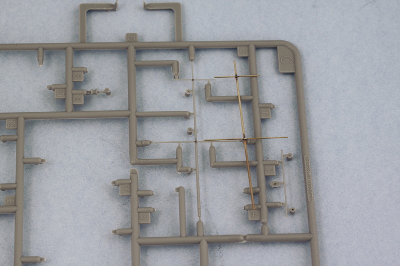
I decided to replace the kit-supplied styrene mast-crossarm piece, C3, with brass rod to provide added strength and durability for this critical piece of the superstructure. My LHS stocks several different diameters of brass rod in their R/C aircraft section and I picked out different lengths of varying diameters and brought them home to see which would do the trick since the cross arms are thinner than the mast itself. I used a Dremel cordless tool and a cone-shaped grinder tool to introduce a taper for the mast but left the cross arms as-is given their relative thinness to begin with. Once I had the main mast done, I cut out the three cross arms again using the kit part as a guide for their length, and then marked their center points with a sharpie. Using a triangular needle file, I notched the main mast in the appropriate places so the cross arms would have a solid contact point.

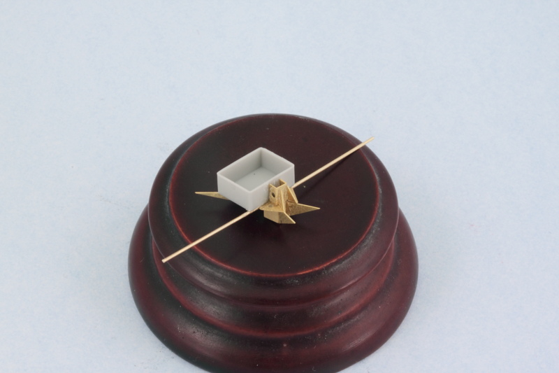
Once all that prep work was done, it was time to solder the cross arms to the mast. I have a Weller variable temp soldering iron and while it was warming up, I used a piece of fiber board and some T-pins to position the mast and cross arms correctly. I used silver-bearing solder paste to place small beads over the join, the soldering iron provided the heat, and voilĂ ! Brass mast and cross arms.  

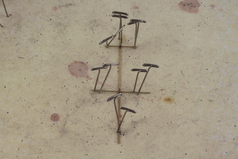
While I was at it, I also created the rear mast and cross arm combo for the aft mast. The third cross arm for the main mast integrates directly with the fire direction platform, so it was secured in place with CA gel separately from the main mast. This also makes life easier when attaching all the PE bits for the underside as the cross arm becomes a convenient 'handle'.

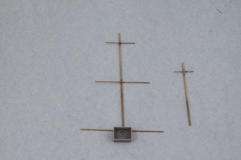
Speaking of PE, the next steps require lots of patience and test fitting with the tripod to make sure the alignment is correct on all the underside supports for the fire direction platform. There are 5 separate parts and the locater marks that Trumpeter provides are a helpful guide but some adjustments are still needed to get the parts to line up correctly and play nice.

If using the styrene masts, Trumpeter has you secure the mast to the platform before adding the rear bracket and rigging extensions. I did the reverse for handling reasons due to the added weight of the brass masts and also to create an added support structure for the mast itself. The rear bracket is made up of 5 different PE parts that all have to come together just so to create the right effect and the Trumpeter instructions aren't super clear on how they all come together. Fortunately the Kagero 3D book includes a very nice look at this area and helped greatly in terms of getting it all lined up properly.

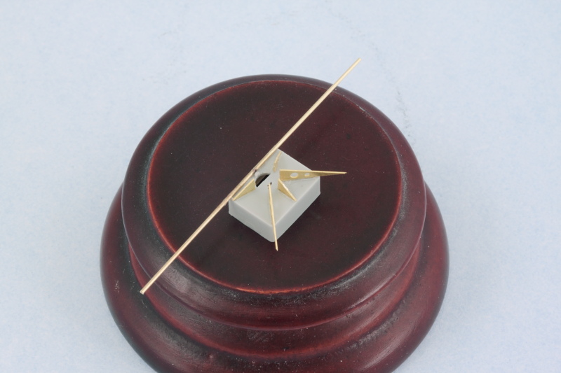
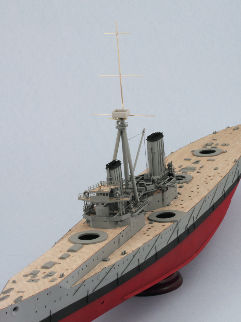
With that done, it was time to pair up the mast and cross arms with the platform. I flattened the rod with a square file so it could have a greater contact surface with the back of the platform and used CA gel to give me a little work time to ensure it was positioned at the right height and alignment with the third cross arm. Once the CA gel had grabbed hold, I used some Aves epoxy putty to stuff the base of the rear clamp structure so it would provide some greater stability and hold for the mast over the long term. A dry-fit test shows everything is lining up properly even though the angle on the camera isn't quite perpendicular.  

Not a bad day's work, the second mast should go faster now that I've learned the 'tricks' of the PE from doing the first one.

JOIN OUR COMMUNITY!

Our community is FREE to join. To participate you must either login or register for an account.

SEARCH FORUMS
FREE NEWSLETTER
By signing up you may also receive reader surveys and occasional special offers. We do not sell, rent or trade our email lists. View our Privacy Policy.