SEARCH FINESCALE.COM

Enter keywords or a search phrase below:

Scratch building the British revenue cutter DILIGENCE

5371 views
6 replies
1 rating 2 rating 3 rating 4 rating 5 rating
  • Member since
    December 2006
  • From: Jerome, Idaho, U.S.A.
Scratch building the British revenue cutter DILIGENCE
Posted by crackers on Friday, October 21, 2016 1:28 AM

INTRODUCTION   History and development of the British revenue cutter.

It is believed the single masted cutter originated from the Dutch during the early part of the seventeen century. These yatchs were designed for use in the shallow costal waters with a simple single mast with a main sail. About 1650, the addition of head sails proved to be an advantage for sailing closer to the wind. Soon, these sails were supplemented by a jib on a jibboom which could be removed. This sail came to be known as a "bezaan" sail. A vessel of this sort was presented to king Charles II while in exile in Hollard. Upon his restoration to the English monarchy in 1661, the "bezan yacht" became a popular royal sailing activity. Later, the bezan yachts in modified form became a standard scouting and advice craft for the Royal Navy.

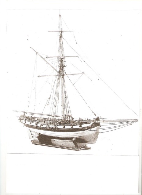
The collection of import taxes and the supression of smuggling to avoid these taxes had been a duty of the royal crown since king John (reigned 1199-1216). In 1699, by Royal Proclamation "Revenue,Customs and Excise" became a seperate entity from the navy. At this time, this service became interested in using cutters to supress smuggling. By the 1750s, the design of the cutters evolved to be like the DILIGENCE. The cutters were constructed mostly in private ship yards at Folkstone, Dover and Shoreham. Thus, documentary evidence of construction, unlike the Royal Navy ships, is scarce and fragmentary. Cutter construction of the hull was mostly clinker built with planking attached to light frames, and armed with 4 pound guns. The cutter's strength and speed is owed to this type of construction. On average, the cutters were 70 feet on deck, 24 feet beam, 11 feet depth of hold and about 161 tons burden.

During the Seven Years War (1756-1763), up to the conclusion of the Napoleonic conflict that ended in 1815, smuggling attained epic proportions to bypass the British blockaid with France. Many Kentish and Sussex towns on the English east coast became smuggling centers of this illicit trade. In retalation, the revenue cutter attained its "golden age" of design and function. The date of the DILLIGENCE is about 1810. These cutters were often crewed by a hard bitten lot of ex-smugglers and fishermen, who knew the ways and strategies of active smugglers. It was a case of using fire to fight fire. After 1815, cutters were heaver built with greater armament, which cut down on the speed and maneuverability.

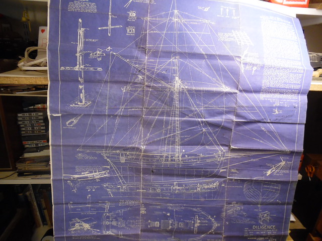
The plan for the construction of the DILIGENCE cutter at 3/16 scale was drawn on September 1947 for the now defunked Marine Model Company of Halesite, Long Island,  New York. It was bought some time during the 1950s. The blue print background is so old that the plan was starting to fall apart at the seams and held together with the adhesion of Scotch tape. Only by carefully placing the plan on a secure flat surface could tracing outline on different parts of the model could be achieved.

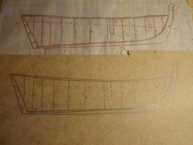
With the help of tracing paper, the hull was copied on partical board, making sure the section lines that were lettered A, B, C forward and numbered 1,2,3, aft from the midship section in an attempt to create a three dimensional hull on a piece of two demensional paper. These stations on the starboard side of the particle board were drilled with small vertical holes to make sure the section lines on the starboard side would agree on the port side when cut out.

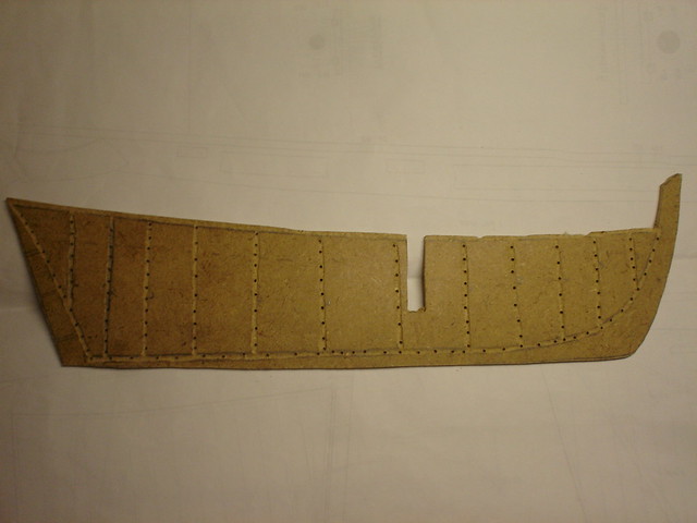
Here is the cut out profile of hull that will hold the starboard side bulkheads. The small vertical holes drilled in the bulkhead slots are a reference point for port bulkheads when glued on the port side of the model. The same is true for the placement of the lower planking. The open slot midship, is where the single mast is to be centered.

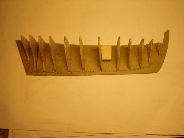
Starboard side bulkheads have been glued in place. The hull planking is yet to follow.

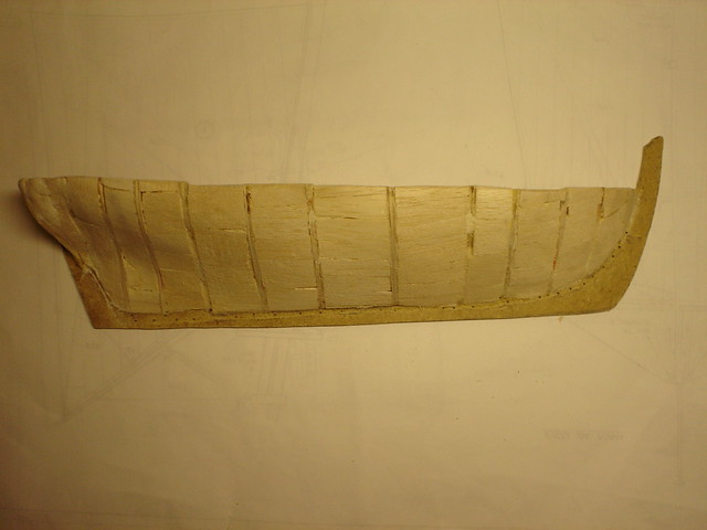
Pieces of balsa wood were inserted and glued between the bulkheads and sanded to the shape of the hull. Balsa wood was chosen because it is easy to sand and shape to the correct contour of the hull. This solid filling will give more adhesion surface for the hull planking in clinker fashion.

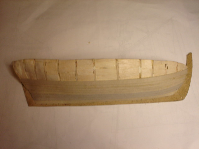
Here is the first stages of clinker planking of the cutter hull. Clinker planking is where longitudinal strips of planks overlap, with the higher plank always overlapping the lower plank. This system of planking evolved during the Viking era on their long ships that terrorized Europe. Strips of thin wood was first tried with frustrating results of splinting and breaking on the DILIGENCE hull. Cutting strips of cardboard from a discarded cerial box achieved better results. The cardboard was easier to shape and adheared easier to the balsa filler between the bulkheads.

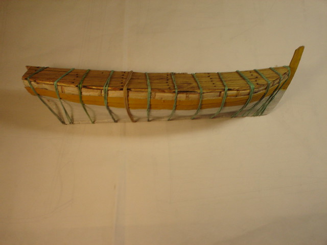
The hull partically completed and deck planks added that were cut from popsicle sticks. The whole arrangement to held together with elastic bands while the glue dries. The wale is to be added later.

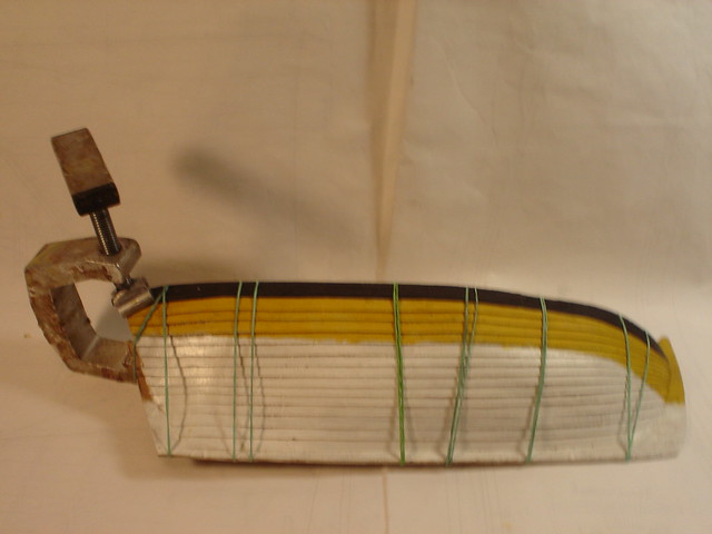
Clinker planking has been finished on the starboard side of the hull. The clamp is holding the black painted wale in place . The white tallow bottom of the hull has been painted with acrylic paint, while the upper section has the yellow ochre acrylic color, common on British ships of that time.

The clock on the wall tells me it's bedtime. Will continue later. Happy modeling Crackers Smile


Anthony V. Santos

  • Member since
    December 2012
Posted by rwiederrich on Friday, October 21, 2016 1:31 PM

Are you building a half model?


Rob

  • Member since
    December 2006
  • From: Jerome, Idaho, U.S.A.
Posted by crackers on Friday, October 21, 2016 2:03 PM

No, Rob. When I continue my posting, you will see that the port half wil be added on the cutter model.

Happy modeling   Crackers   Stick out tongue

Anthony V. Santos

  • Member since
    December 2006
  • From: Jerome, Idaho, U.S.A.
Posted by crackers on Saturday, October 22, 2016 12:58 AM

Constructing the bulwark for the starboard side of the model on a strip of wood. Rather than cut out each individual gun port with a hobby knife and having the risk of the wood splitting, the bulwarks were cut out in pieces and glued together. Individual stanchions were then cut fron stock and glued in place. Next, the bulwark was painted the usual red acrylic and the rail painted black and added on.

This is the tricky part. Bending and glueing the completed bulwark to the starboard half-model, very carefully, I might add, to prevent having the bulwark split in pieces. This was accomplished very slowly over a couple of hours with the aid of paper clips and elastic bands. The black acrylic wale was also secured in place. One can see that the rail on the forward section has already split, which was later repaired.

Here is the completed starboard half-model with the addition gun port lids, a davit for the stern dinghy, the rudder and channel with dead-eyes attached. From an ugly representation of a cutter, an acceptable rendition of a model is starting to emerge. The hobby knife gives a better idea of the scale of the half-model rather than the retractable tape ruler.

Mounted on a cradle, brass guns were added for a dry run appearance with a swivel gun and an anchor for the finishing touches.

A bird's eye view has the tiller and inboard pin rail. The deck planking were cut to size from popsicle sticks and stained. The tar cauking between the deck planks was made with a black felt-tip pencil rubbed on each edge of the planking.

Another dry run view from the port side of the cutter half-model. Just for show, the deck guns, which would be four pounders on a real British revenue cutter, were placed temporarily just for curious viewing. The tiny vertical holes on the center hull bulkhead were guides to make vertical groves to glue the port bulkheads. The peg amidship is where the single mast will be inserted and glued in place.

Now to work on the port side of the cutter. Traced from the blueprint plan, the port stations of A,B.C, and 1,2,3, were transfered to particle board and cut to size, then glued to their proper location and filled in with balsa wood and sanded to desired configuration as was done on the starboard side. When completed, the clinker hull planking was added. To accomplish this task, a box like cradle was constructed to hold the up-side-down starboard side of the cutter, so as to have a stable platform to complete the port side work.

When the port half-hull was completed, the two halves were joined together with glue and held in place with elastic bands for curing. The deck has not been stained, as seen on the starboard side. Deck furniture and other items have not been assigned to their proper locations yet. The peg to denote the future mast is still in its temporary location.

Here is the point were good vibes stroke the ego. The hull is completed. The stern boat is in place as well as the small rowing gig stowed at the center of the cutter. Deck furniture like the companion way, the binnacle, knight heads and anchors are at their proper location. Not seen, the bowsprit is also secured. The single mast and yards with their pully blocks attached is ready for attachment. Next, the sails will be made as will be seen in following presentation.

Threading the dead-eyes presented a problem that could be solved with a little ingenuity of a special jig. This jig is composed of two wood halves that closed together and held in place with two elastic bands top and bottom with the two dead-eyes secured in the middle.

While the dead-eyes are secured, a needle and black thread is wove through the holes in the dead-eye. The black thread is first run over a block of bee's wax to preserve the life of the thread. There is a certain pattern on how the thread is to be woven on the dead-eyes. This procedure is found on most ship building manuals.

The jig is released to present the completed threaded dead-eye.

The clock on the wall tells me it's bedtime. Next posting will be about making the sails with their reef points, followed by the conclusion of this thread.

Happy modeling    Crackers Indifferent


Anthony V. Santos

  • Member since
    July 2013
Posted by steve5 on Saturday, October 22, 2016 1:12 AM

very , very nice cracker's , have you got a bunch of elve's helping you , because gee your knocking it out , at a hell of a rate , LOL .


  • Member since
    August 2007
  • From: back country of SO-CAL, at the birth place of Naval Aviation
Posted by DUSTER on Saturday, October 22, 2016 11:19 PM

This a grand tour of old scool model building. But you make it understandable and easy to follow.

Steve

Building the perfect model---just not quite yet  Confused

  • Member since
    December 2006
  • From: Jerome, Idaho, U.S.A.
Posted by crackers on Sunday, October 23, 2016 1:40 AM

Sails for the cutter DILIGENCE which include, outer jib, innerjib, foresail jib, mainsail, top sail, top gallant sail and main sail gaff sail. I chose silkspan as the sail material bought from Bluejacket Ship Crafters of Searspoint, Maine. Unlike cloth, silkspan, which model airplane builders use to cover the frames of their models, is strong and more to scale like past sails. The sails were colored in a diluted water solution of light tan acrylic paint in a pan. Coffee or tea coloring would eventually deterioate the sail over time. All sails were hemmed with cringle and clew lines attached at the proper edges.

For authentication of sails on sailing ships, reef points should be included. Reef points were short lengths of cordage which hung loose in front and behind the sail. When the sail was furled, the reef points were looped and tied together on top of the spar to prevent the sail from unfolding. They were also used to shorten the sail in strong winds. The tools required for this project are, glue, tweezers, a wire hook, an awl to puch holes in the silkspan and needle and thread. Of upmost importance is a cardboard jig to aline the reef points held down by paper clips.

The first process is to make a cardboard jig with holes made with an awl. These holes represend the locations of reef points pictured on a sail from the plan. After the horizontal holes are punched into the jig, the jig is placed onto the silkspan sail and marked with a pencil in a twist motion to creat a dot on the silkspan. The jig is removed and the awl then punches a hole on the pencil dot the sail at each horizontal interval.

A second cardboard jig with a series of vertical cuts made with scissors that correspond to the punched holes on the sail is placed below the holes so the the top hole is directly above the slits on the cardboard jig. The jig is secured in place with two paper clips at each end. A needle and thread representing the reef points is stuck in the first hold, pulled down to the first slit on the jig, pull up in back of the sail and stuck into the second hole, pulled down to the second slit of the jib and again repeated in a horizontal motion until the end of the sail is reached. When this task is completed, glue is applied in the back of the sail until dried to secure the threads. When the glue dries, scissors cuts the threads on the very BOTTOM of the jig. For reef points on the back of the sail, a stip of silkspan is cut and the same procedure as described above is created. When the glue dries, this strip is pasted on the back of the sail directly behind the row of reef points on the front of the sail.

Hopefully this is the results achieved from the lengthly dialog on the previous panel. The reef point threads refused to hang down limply. So, with tweezers, each thread had to be glued in place. The left side of the sail has the reef points in proper position, while the right side has the reef points threads pointed in all directions. The horizonal row of holes on the silkspan sail will be for another row of reef points that were common of sailing ships.

This is the same procedure for the second row of reef points on the sail. Rather then scissors, a razor blade accomplished the trim with better results.

Finally, the completed cutter model. Hallelujah ! Before closing this thread, it should be noted early 19th century revenue cutters had their own signal flags and codes. Being small craft, it was not easy to accomodate the large number of signal flags of the general code. During the middle of the proceeding century, a special signal arrangement was introduced for cutters. The signal flags on the DILIGENCE model reads,"smugglers in sight". The ensign flag attached to the peak of the main sail consisted of a red field background with the union crosses on the upper corner. On the center red field had a yellow crown to signify a royal decree. The pennant on top of the mast consisted of a red triangle with the same yellow royal crown. The ensign flag was flown on cutters from 1805 to 1872.

Sources of information for this thread:

"The English Cutter", by D.L. McCalip, Model Shipwright, #27, March 1979                        

"Flags for Revenue Cutters" By Alec Parves, Model Shipwright",#27, March 1979

"Anatomy of the Ship,The Naval Cutter", by Peter Goodwin, Phoenix Publication 1991

Happy modeling    Crackers   Wink Beer

Anthony V. Santos

JOIN OUR COMMUNITY!

Our community is FREE to join. To participate you must either login or register for an account.

SEARCH FORUMS
FREE NEWSLETTER
By signing up you may also receive reader surveys and occasional special offers. We do not sell, rent or trade our email lists. View our Privacy Policy.