Things are moving fast and furious. I was working on a couple of fronts today all progressing forward.
Areas of attention were: the central column, bloomers, power switch for base.
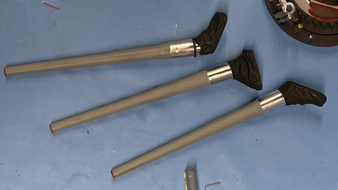
I did the bloomers first with a mix of Tamiya Rubber Black and NATO Black. I used 3M blue tape to mask the little flange at the rear of the slide area and the tape pulled paint of the barrel. I resprayed and fixed it. I wondered why the airbrush was gumming up so badly. I inadvertently used IPA to thin the Life Color paint. Like Vallejo, these acrylics not only don't thin with alcohol, they form rubbery blobs that clog airbrushes. I realized my error, cleaned up the mess and then thinned it with AK universal acrylic thinner. Bloomers are not glued here. I will glue them to the turret first, then install the guns.
A critical step was figuring out how long the central column needed to be. The column I was using up to this point was just a guesstimate that didn't take into account the actual combined depth of the wooden base AND the 3D printed mounting flange. I measured that combined distance, assembled the stack with another, overly long, column and marked this depth.
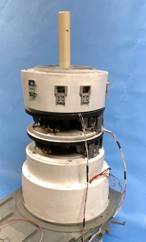
Here's a closer look at that mark.

I took this piece and cut it off at the mark on the chop saw.
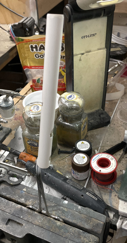
I then had to cut the various access points in the column for the wiring harnesses to go under the base. I just went at it with the carbide router. They didn't to be pretty since they're out of sight (for the most part). I then clamped on a forceps and sprayed it flat white. I almost blew it by starting to run wires before painting. I caught myself after just doing one wire set. I had to keep my wits about me when figuring where the access ports were going to go. They had to align with the general direction that the wiring was approaching the column.
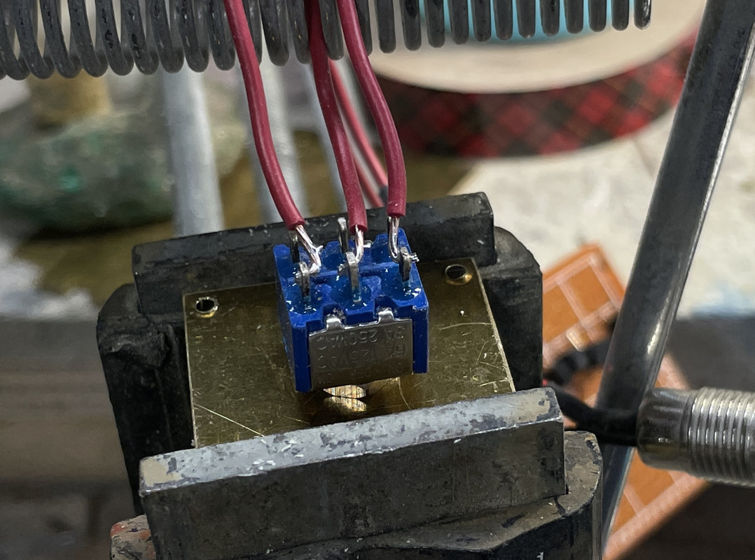
While this was drying I got to work installing the missing power switch in the wooden base. While I felt bad about hacking into the beautiful piece of woodwork crafted by my friend Bryant Mitchell, it was necessary. I have a few left over double pole/double throw toggle switches from building my model railroad. I only need one pole, and one throw for that matter, but I can use both throws by making the output come from both sides. So middle is off and switching in either direction is on.
I consider myself a pretty good solderer, but after taking this image, the outer two leads just fell off. The switches are German and I got them when first building the railroad when on assignment at Henkel in Düsseldorf, Germany. That was 1999, which makes this switch 23 years old and the terminals had oxidized. I went at them with a file and resoldered the wires correctly.
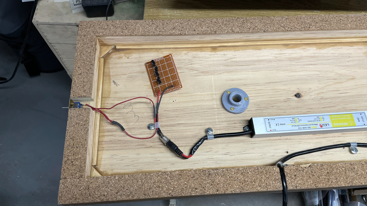
Here's the wiring completed as of now. The circuit board is just floating there since I have to terminate a whole lot of LED leads on its underside.
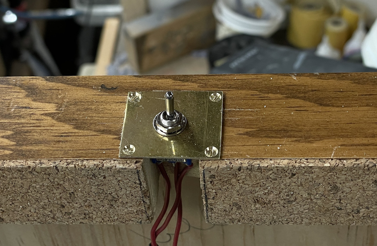
And here's the exterior.
By the time I got done this sub-project, the column was dry and the wiring could begin in earnest. I first fished the twin lead from the bottom of the electric deck (lights the first projectile flat) which goes directly from the top to the bottom.
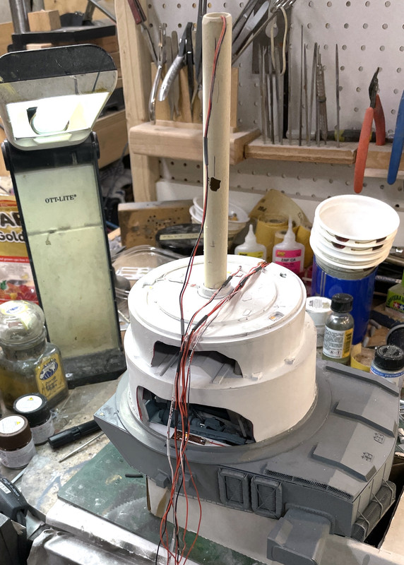
Some of my wires were short. I was estimating the length during the LED wiring phase, but shortchanged myself. I had to extend some about 6" just to have enough slack to do all the terminating without straining anything. I used a piece of heavy gauge solid-core wire to fish the bundle through the access hole and out the bottom.
Here's the entire mass now fed through the frst access hole. There are two more sets that need to go in. I made a large notch in the e-decks outer flange so the wiring wouldn't affect the deck nesting. I overcoated it with Bondic to secure them before fishing. I may have to cut one more access hole for the two-wire leads from the 2nd Projectile deck.
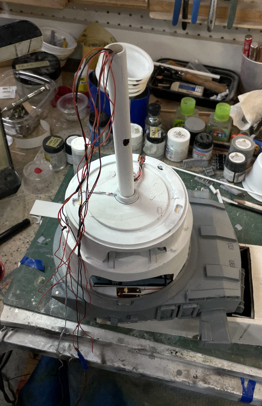
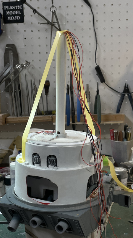
With the harness in, it was time for another milestone; the gluing in of the column's top into the boss under the electric deck. I used epoxy for this critical joint. It needed to be plumb in both axes and I taped it after putting a square around it to ensure it was. The boss is larger and the column was able to shift a lot.
I need to paint the foot rungs on the ladder pieces a printed several weeks back and then install them on deck at a time as I install each projectile deck. There theoretically is a ladder on the powder flat's exposed column, but it's completely hidden by the foreground's powder trunk unit and therefore, I can't get to it to install the ladder, nor will it ever be viewable. Therefore, it ain't gonna be there.
From one angle...
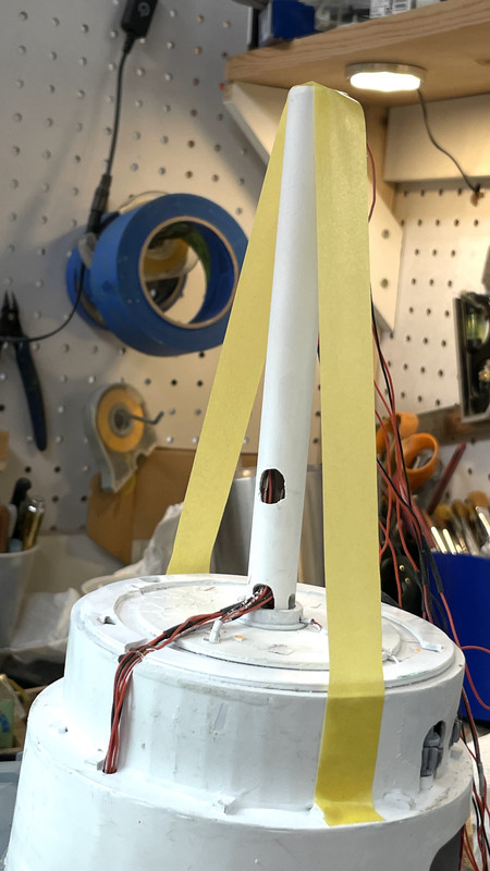
And 90 degrees around. The wiring coming up the back of the electric deck is at the rear and out of view. I also touched up all the flat white that got disturbed when epoxying the pan and e-decks.
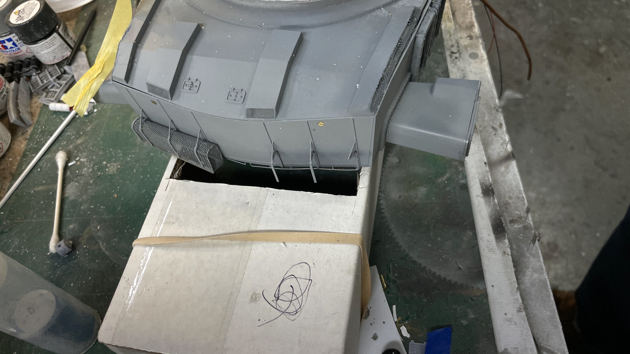
And of course something broke. Those $@T)Y)% float net baskets are just too fragile to be around this level of heavy construction. I'm going to wait until it's just about all done and reinstall it.
Tomrrow will see the stack come together. I really think I need to build the enclosure BEFORE the stack is fastened to the base. I'm going to have to trial fit everything and don't want the chance to bump something. So I will be building the case sooner rather than later. Actually installing the stack into the base will only take a couple of minutes. Since I have to terminate all those LED wires with the model built and on the base, I will also like the enclosure built so I can tip the entire model on it's side or upside down without the model supporting any of that weight. Speaking of weight, resin is heavier than a styrene model. Between the mass of the base, the acres of 1/16" plexiglass and the dense model, this thing's going to be heavy!
Stay tuned!