Back with an update. It's been tricky trying to create some time for this build, but that always seems to be my excuse. I did manage to get through what I wanted out of the tail gear section and continued work on the cockpit.
Here is more of the cockpit coming together. I'm taking my time here to ensure all the add ons are lining up and have space enough to fit properly.
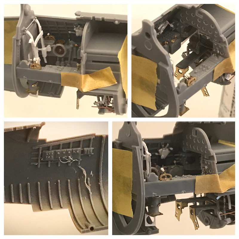 Untitled by Britt Vallot, on Flickr
I fought real hard not to cut all this side wall detail out. It's really not all too bad. I did have redo the throttle quadrant. That just wasn't going to cut it. What you see here is pretty simple. I cut and trimmed the kit piece down and built back up from it. Thin cuts of plastic card make up the body of this device. There's a small rectangular shim to give some space to separate where the different levers will fit in and another small cone shaped layer on top of it. I also added a cone shaped piece of lead foil to make up the rear portion and provide some depth. Here's some examples of the real thing.
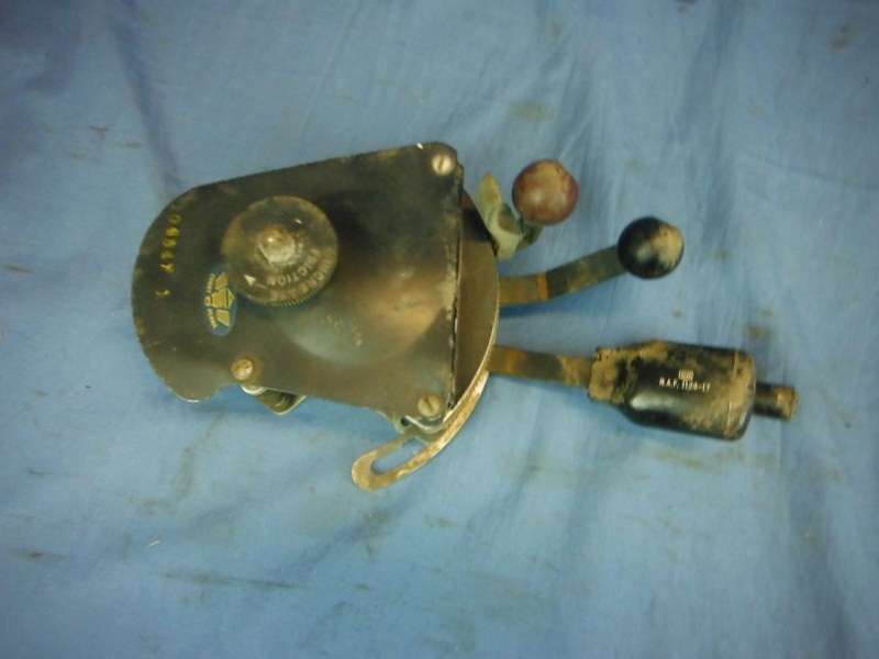 Untitled by Britt Vallot, on Flickr
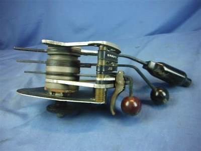 Untitled by Britt Vallot, on Flickr
I hope you can see well enough how that's coming together here. Hopefully, after some primer this will be better viewed.
Moving on, I started dry fitting the fuselage halves together.
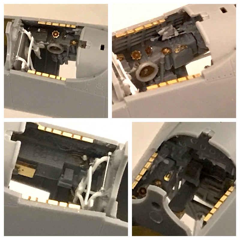 Untitled by Britt Vallot, on Flickr
There are four long stubs poking out of the left side IP. This is where the throttle quadrant controls will pass through the IP to control the engine. I ended up getting just a bit too much CA on here when gluing my slide tubes to make up the controls and I've since cut them off. I'll be reattached to the IP and match them to the throttle later on. They are too small and delicate to do it more than once without making a bigger mess.
The Tail Gear
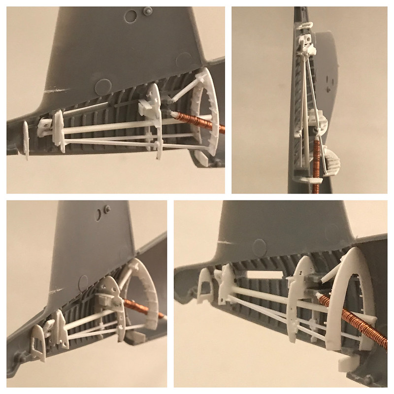
I'm a sucker. I'll just tell you up front. Many of you can breeze past this part if you'd like and it won't hurt my feelings a bit. This largely will go unseen, but I feel the need to develop any exposed opening on an aircraft. So here it is.
Working up the ribbing and various bulkheads isn't real hard. It just takes some eyeballing and lots of sanding. Having some specs on hand can help, but it's important to realize that the kit itself has it's own thickness to account for and at the end of the day you have to make fits according to what is in front of you. Here's what I have to share. Much of this gets overwhelming to look at so I've broken it down into a few parts.
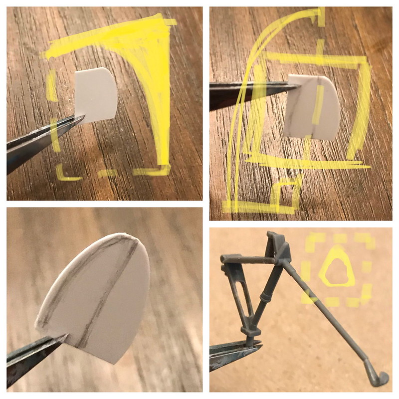 Untitled by Britt Vallot, on Flickr
Easy enough to see what's going on here. I added some coaching marks to help explain. You're essentially finding one side of that curve for the fuselage half and then mirroring it. Nothing fancy about it. I find this to be quite effective. Start a little larger at first as it's easier to take it off than put it on. =] For the tail hook...many of these got removed to lessen the weight once they were committed to forward island bases. I checked through photos and found in enough of them that Walsh had his removed as well. So--snip! The triangular shape you see in front of it should be hollowed out. Tamiya has molded it as a solid piece but the real thing is basically a band of metal that's bent forming the triangle you see here. I have no name for it and can not quite come up with a possible function for it. Anybody out there with an answer...I'll be grateful to hear it. (Edit - After more digging for various other parts of the build I stumbled upon a name for this. I've seen it labeled as a turning mechanism. Possibly for other vehicles to push/pull it into place) But nonetheless, this is the true shape of it. This might actually be a little undersized, but it was strong and I left it as I was able to carve and sand it proper. I didn't want something flimsy that would later pop off.
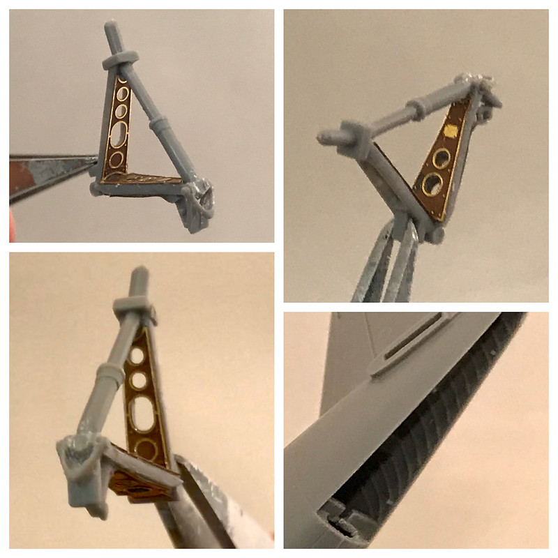 Untitled by Britt Vallot, on Flickr
Next, I utilized some of the PE for the tail gear itself. It requires a bit of drilling and cutting but nothing so extreme. Pretty self explantory. I resisted the urge to cut the upper section out and add some side strips instead of laying the upper PE on top. An I-beam shape is more accurate but I didn't want to chop this up and make it weaker possibly when having to add it later. Did that once on a mustang and found it harder to fix after the fact. It tucks away pretty well and is still and nice addition.
Next comes the framework that all of this sits in.
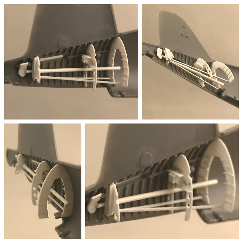 Untitled by Britt Vallot, on Flickr
This speaks for itself. I'm just building up what I see on the real thing. If there's any specific questions, then please stop me. That's what WIPs are for! =]
Much of this is just made from various thicknesses of plastic card/strips, c channel in there, some rods of various thicknesses, etc.
Intermediate step to check my math.
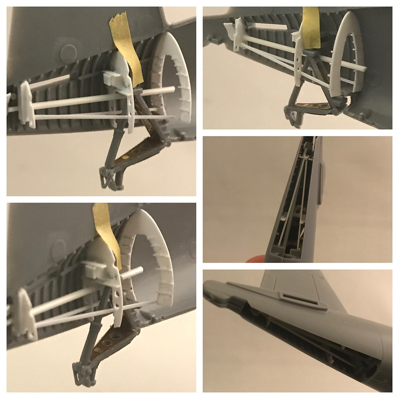 Untitled by Britt Vallot, on Flickr
A few extra parts to liven things up. Everything seen here is amounts to rudder control (box behind middle bulkhead minus the wiring for it...comes later after priming), elevator controls (long rod--interesting note at the end), tail gear retraction, and stearing for the tail gear.
 Untitled by Britt Vallot, on Flickr
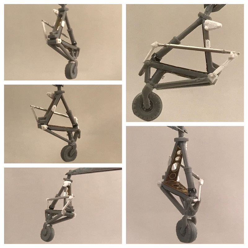
I continued to dress up the tail gear itself. One major addition or rather subtraction is the carving out wheel. This part is obviously molded solid and likely for reasons of the molding technology but it should be a thin flat metal housing that the wheel fits onto. Opening this up isn't hard and makes a huge difference. I started with my No. 11 exacto knife and began drilling a small hole that I slowly used to get leverage to carve out the insides. Nothing to it. Just slow working the blade to trim away what doesn't belong. I even cut away a small groove from off the tire so I can drop some detailer wash in later to create some shadow. I also cut the tire off after finishing so that I can reposition it. I currently have it facing backwards to show a corsair that was backed into its place on the PSP matting. Just a simple thing to add interest.
 Untitled by Britt Vallot, on Flickr
The other notable feature here is what operates the tail hook. The Eduard PE gives you a flat piece that resembles this shape, but blah--screw that. The actual object is some small, hydraulic driven tube that builds up easy enough with slide tubes. I secure this with a white glue which provides a little wiggle room for movement that CA will not. When test fitting it can be a huge pain to watch tiny pieces fly off to never be found again...even when they are right in front of you...without carpet...and a clean work area...mostly clean. So the white glue is strong and flexible and a big part of my build process. And if something needs correcting, it can be pulled off and cleans right up. Any other time I can build something out of plastic I usually try to. That allows me to weld it all together with the Tamiya Extra Thin Cement and keep it strong and lasting.
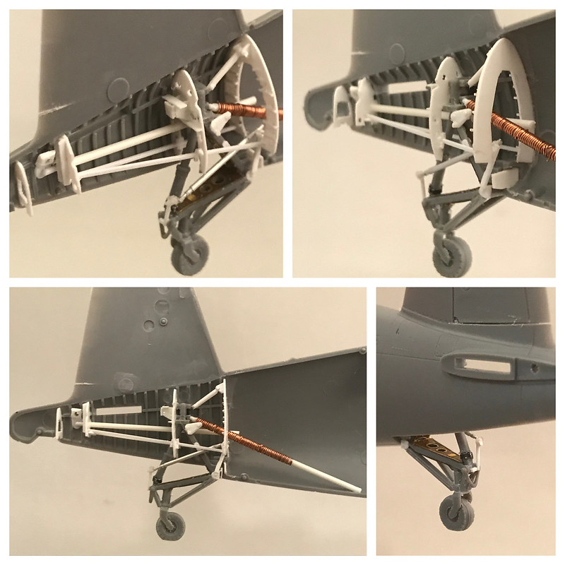
Here's the next progression of how this is shaping up.
 Untitled by Britt Vallot, on Flickr
Again, any questions out there about any of this please don't hesitate to ask. I plan to stop here as this is sufficiently busy. Rest assured, none of this will be visible after all your hard work. Even those pesky little flashlights will find it hard to search out this area of the build.
 Untitled by Britt Vallot, on Flickr
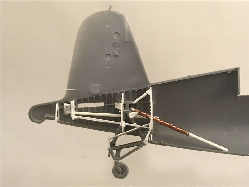
This is set of views is to give you a picture of where we're at with the scratch building add ons. Not too bad and worth the time. You know, if you're a masochist.
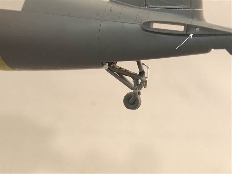
One extra point I wanted to share was a happy little accident I stumbled onto with Tamiya's engineering. On the inside of the tail section where the elevator bar is received by the fuselage tail, you can see a small nub protrude. This nub actually lines up perfectly with what controls the elevators. I naturally jumped on the opportunity to drill this out and line it up with the actual elevator control on the inside and I plan to place a brass rod through it and into the elevators which will be moved into a forward stick position making them droop. =]
 Untitled by Britt Vallot, on Flickr
This corresponding position on the elevator is perfectly aligned. It was like they were asking me to do it. =]
 Untitled by Britt Vallot, on Flickr
 Untitled by Britt Vallot, on Flickr
That concludes this section. All that's left before prime and paint is to add the hoses and wiring in the cockpit and solve my exhaust stack problem. Thanks for watching.