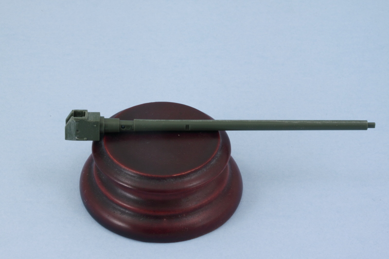
It was finally time to tackle the main event, ZiS-3 76.2mm gun. There are 6 steps in the instructions devoted to getting it together. Starting in Step 26, the three-part breech is assembled and added to the main gun barrel. The step also adds the breech block but I left it off, for now, to make it easier to paint and detail it later. The parts go together nicely with just a little bit of sanding necessary to get the joins to disappear.
Step 27 adds the recoil mechanisms and slide tray. A polycap goes in between the recoil portions and is what allows the gun to hold its position and remain elevatable. The recoil guard had some small ejector marks that needed to be removed on its inside face and I also added the block activation lever mechanism as called for. This can only be positioned one way, with the block closed, due to the use of 2 locating pins to get it in the right spot.
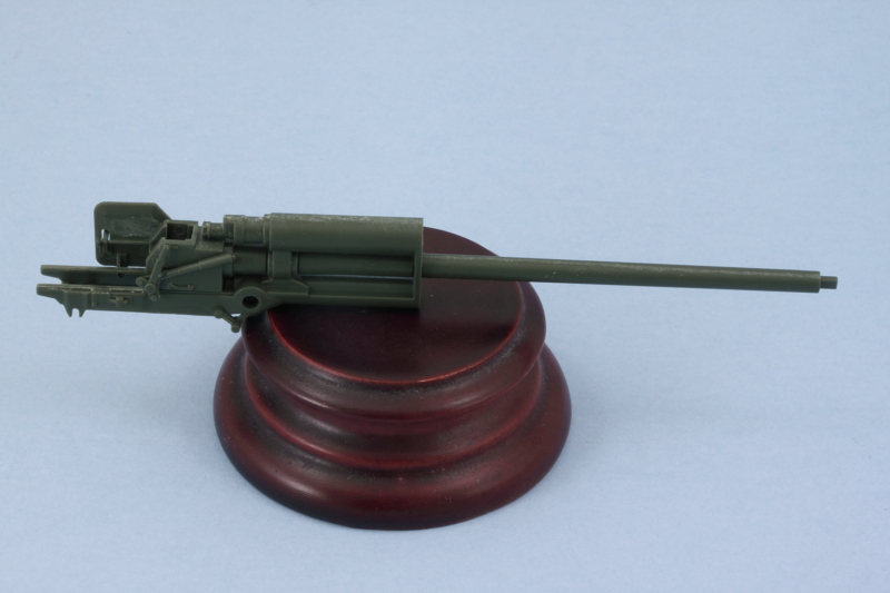
Step 28 continues the assembly with the addition of the side supports for the gun mount and the mount post that supports the gun in the hull. It also adds the part of the gun under the recoil tray that includes the rear part of the travel lock.
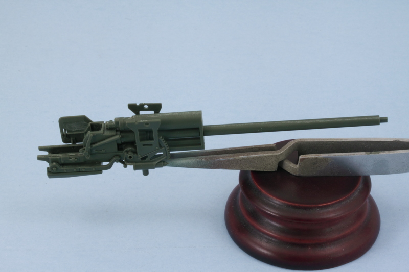
Step 29 is a fairly simple one, it adds the small support tabs for the mantlet sides as well as the elevation and traverse mechanisms along with their hand wheels. I left the wheels off for the time being to make it easier to paint the gun and its details and will add them later. It's also important to note here that the smaller wheel, C77, has to be positioned just so in order for the gunner's hand to match up with it if you plan to use the kit-supplied figures. The instructions include a little 'note direction' callout to help with this but it's not an exact thing to try to eyeball without the gunner already built to help you out. :) I also left off the gunner's sight but will add that later on.
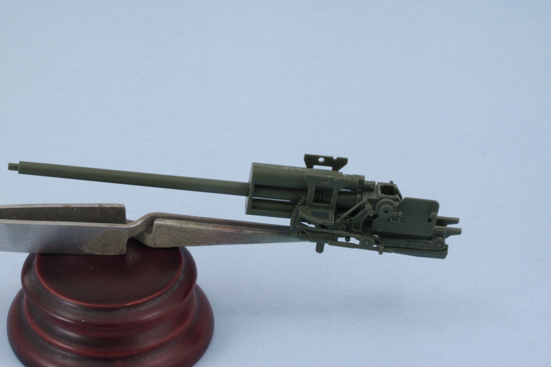
Step 30 adds the sides and top of the armored mantlet for the gun. I used a little bit of finger pressure to flex the sides in just a touch to mate up properly with the top and applied liquid glue so it would grab and create a solid join.
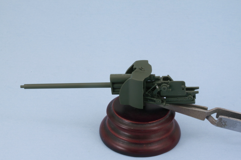
Step 31 assembles the external armored covers for the recoil mechanism and the front plate for the mantlet. I assembled the two halves of the cover first, then added the front plate, then added it all to the mantlet front plate. Just a tiny amount of putty was needed at the top to close up a small gap with the weld seam that's molded on the mantlet front plate.
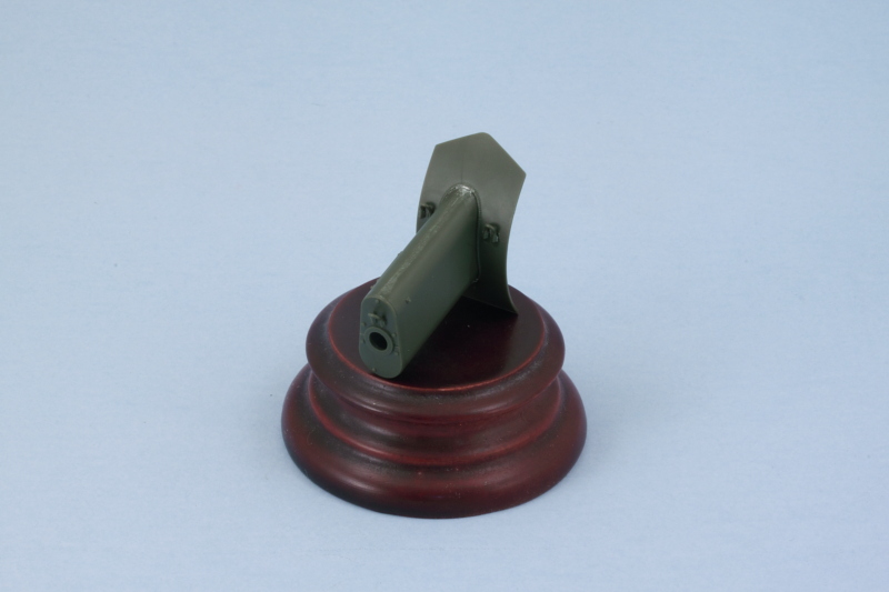
The step also calls for the assembly of the muzzle brake. This is a split-half arrangement, but careful use of liquid glue and some light sanding took care of the small join seam. The recoil cover and mantlet front aren't meant to be glued onto the gun and instead rely on a tight friction fit to keep it in place while still allowing the gun to elevate. The instructions give you a heads-up on this by clearly telling you NOT to glue the curved plate to the rest of the mantlet structure.
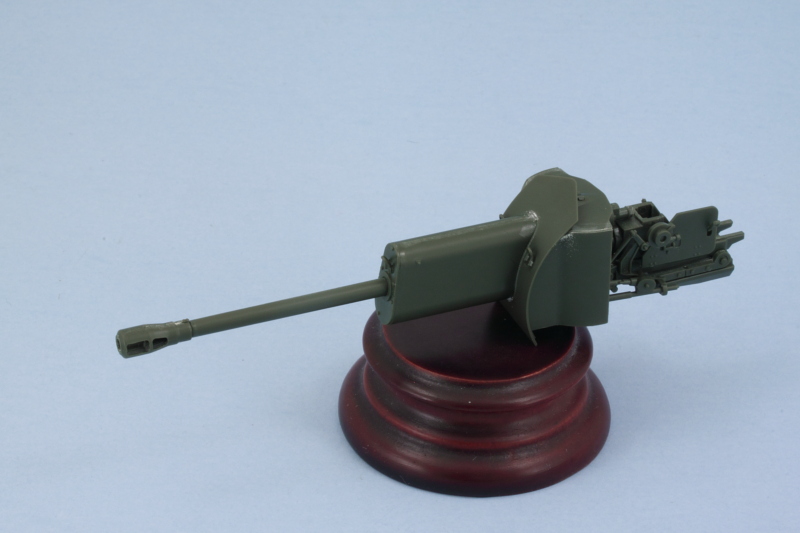
Step 33 has you install the gun into place using the polycap and that also allows you to pull the gun in and out for test fitting before committing to the final installation. Step 35 assembles the mantlet top armor that locks the gun into place out of 3 different pieces that all fit together to create the spaced plate arrangement. A quick check with the gun shows everything lining up like it should. It also showed me that I had missed one of the lifting eyes on the engine access hatch on the front hull, so that got checked off while I was at it.
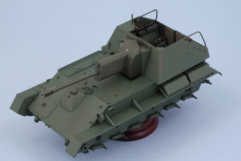
That meant it was time for paint! I airbrushed the gun assembly using the same process on the hull.
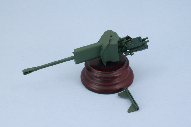
Since this was the last time I had planned to have the airbrush set up with the hull colors, I placed the gun and mantlet cover and checked for consistency. After some minor changes and adjustments, it all looks like it belongs to the same vehicle! :)
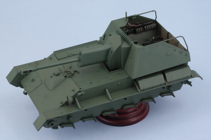
Next up will be dealing with all the hull equipment that needs to go on the main deck and other spots.