SEARCH FINESCALE.COM

Enter keywords or a search phrase below:

Tamiya 1/35 SU-76M--Complete 04/10/16

9037 views
101 replies
1 rating 2 rating 3 rating 4 rating 5 rating
  • Member since
    July 2003
  • From: On my kitchen counter top somewhere in central North Carolina.
Posted by disastermaster on Friday, April 1, 2016 4:21 PM

the doog

Cool beans, Bill! It's all looking great, as usual!

Playing on the radio right now.... "HEY LA, HEY LA, MY BOYFRIEND'S BACK..."! Big Smile

(hey man, it's the 21st century, don't freak out, lol)

           Yay........ http://www.wineonthekeyboard.com/wp-includes/images/smilies/AngelSmilie.gif http://www.clicksmilies.com/s1106/engel/angel-smiley-023.gifhttp://www.4smileys.com/smileys/angel-smileys/angel_smiley007.gif  "The Angels"

                             Good stuff!

 https://i.imgur.com/LjRRaV1.png


  • Member since
    July 2004
  • From: Texas
Posted by wbill76 on Friday, April 1, 2016 3:57 PM

NucMedTech

Bill this is coming out great. Kind of caught me by surprise as it is not german, lol. Am I correct in assuming this is out the box without any am parts? If so, it shows the quality of the molds, everything looks sharp and crisp.

-StephenCowboy 


Thanks Stephen! You are correct, I'm building this one OOB with no AM added. I have been following the 'IPMS Rules' for a true OOB (it's ok to remove stuff like drilling out or thinning stuff down) effort so people can see how the kit comes together. I agree with you on the quality of the molding, Tamiya doesn't disappoint in that regard. Beer You're right about it being something 'a little different' but then variety is important to prevent burnout and broaden your horizons from time to time. Big Smile 

  • Member since
    September 2006
  • From: Central Texas
Posted by NucMedTech on Friday, April 1, 2016 3:47 PM

Bill this is coming out great. Kind of caught me by surprise as it is not german, lol. Am I correct in assuming this is out the box without any am parts? If so, it shows the quality of the molds, everything looks sharp and crisp.

-StephenCowboy 

Most barriers to your successes are man made. And most often you are the man who made them. -Frank Tyger

  • Member since
    July 2004
  • From: Texas
Posted by wbill76 on Friday, April 1, 2016 11:50 AM

Thanks Rob! Sometimes the old trick book has to be hauled out even on new releases like this one. Wink Beer 

  • Member since
    October 2015
Posted by Modelrob on Friday, April 1, 2016 5:08 AM

The mesh came out looking good. The build is coming along nicely.

Robert

  • Member since
    July 2004
  • From: Texas
Posted by wbill76 on Thursday, March 31, 2016 7:05 PM

I spent the day working mostly on the gun's details so I could get it installed permanently into the compartment. That involved working on several different areas including the gunner's sight. The kit part has solid faces all around, so I used a micro-drill to open up both the eyepiece portion and the top sight opening itself. I also used the same approach as with the fighting compartment to weather the rear parts of the gun and mount to get them to match up. 


Detail work also included getting the breech block painted and installed and the bare metal surfaces on the recoil sled picked out. 


With the gun now detailed, I installed it permanently into position. I made sure to firmly press the gun all the way down into the polycap's mount since it needs to be down far enough not to cause any interference with the top mantlet piece that locks it all in place. A little bit of liquid glue around the triangle portions of the mantlet piece and some careful gentle finger pressure got it all joined together. 


Once I had that done, I also worked on detailing the 3 periscopes that go into the fighting compartment. The kit parts are molded in one piece in the green styrene, not clear, and had an ejector mark on one side that had to be dealt with. To simulate the clear faces, I applied some enamel Steel followed by a dose of Tamiya Clear Smoke. Tamiya does include a clear sprue in the kit (oddly enough, only 1 of the 8 parts on that sprue actually gets used, the headlight lens) but I don't think it's really designed for this kit per se. The clue is that the sprue includes 4 sets of goggles that have no possible use on this vehicle or its figures, so perhaps they just repurposed it from another kit or set? Either way, it wouldn't have been hard to have clear periscopes for a little more detail potential since they are so prominent in the fighting compartment. 


I also started on the hull details by working on the side air intake. This is molded solid with a grill pattern so I used a thinned wash of MM enamel Gunmetal to darken up the spaces in the mesh pattern. A careful drybrushing of the 50/50 OD/Russian Armor Green with a small square tip blender brush brought the mesh pattern back out so it would have some depth (or the best possible simulation of it at any rate) to its look. 


Tools and the exhausts are next! 

  • Member since
    July 2004
  • From: Texas
Posted by wbill76 on Wednesday, March 30, 2016 4:39 PM

Bish

, yes, the main gun barrel is provided as one piece. Wink 

Gamera

, thanks as well! You may be right, I haven't built any of the other models out there of this particular vehicle so can't say one way or the other. Beer 
  • Member since
    November 2009
  • From: SW Virginia
Posted by Gamera on Wednesday, March 30, 2016 2:41 PM

Nice work there on the gun and mount. I have a feeling it probably didn't fit anywhere near as well on the older non-Tamiya versions. 

"I dream in fire but work in clay." -Arthur Machen


  • Member since
    December 2002
  • From: Bury St Edmunds, Suffolk, England
Posted by Bish on Wednesday, March 30, 2016 1:25 PM

Great work build and really nicley done WiP. I agree about how this is engineered, looks really well done. Is that barrel one piece.

I am a Norfolk man and i glory in being so


On the bench: Airfix 1/72nd Harrier GR.3/Fujimi 1/72nd Ju 87D-3

  • Member since
    July 2004
  • From: Texas
Posted by wbill76 on Wednesday, March 30, 2016 10:10 AM

stikpusher

Yes I like how the kit is engineered to build up around the barrel and breech. Wink


I agree Stik, the Tamiya engineering is pretty well thought out for this area. 

  • Member since
    July 2004
  • From: Sonora Desert
Posted by stikpusher on Tuesday, March 29, 2016 7:57 PM

Yes I like how the kit is engineered to build up around the barrel and breech. Wink


F is for FIRE, That burns down the whole town!

U is for URANIUM... BOMBS!

N is for NO SURVIVORS...

       - Plankton

LSM


  • Member since
    July 2004
  • From: Texas
Posted by wbill76 on Tuesday, March 29, 2016 5:34 PM

It was finally time to tackle the main event, ZiS-3 76.2mm gun. There are 6 steps in the instructions devoted to getting it together. Starting in Step 26, the three-part breech is assembled and added to the main gun barrel. The step also adds the breech block but I left it off, for now, to make it easier to paint and detail it later. The parts go together nicely with just a little bit of sanding necessary to get the joins to disappear.   
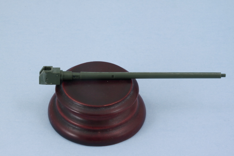


Step 27 adds the recoil mechanisms and slide tray. A polycap goes in between the recoil portions and is what allows the gun to hold its position and remain elevatable. The recoil guard had some small ejector marks that needed to be removed on its inside face and I also added the block activation lever mechanism as called for. This can only be positioned one way, with the block closed, due to the use of 2 locating pins to get it in the right spot. 
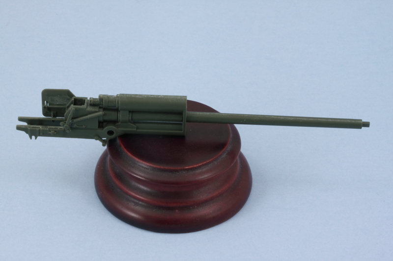


Step 28 continues the assembly with the addition of the side supports for the gun mount and the mount post that supports the gun in the hull. It also adds the part of the gun under the recoil tray that includes the rear part of the travel lock. 
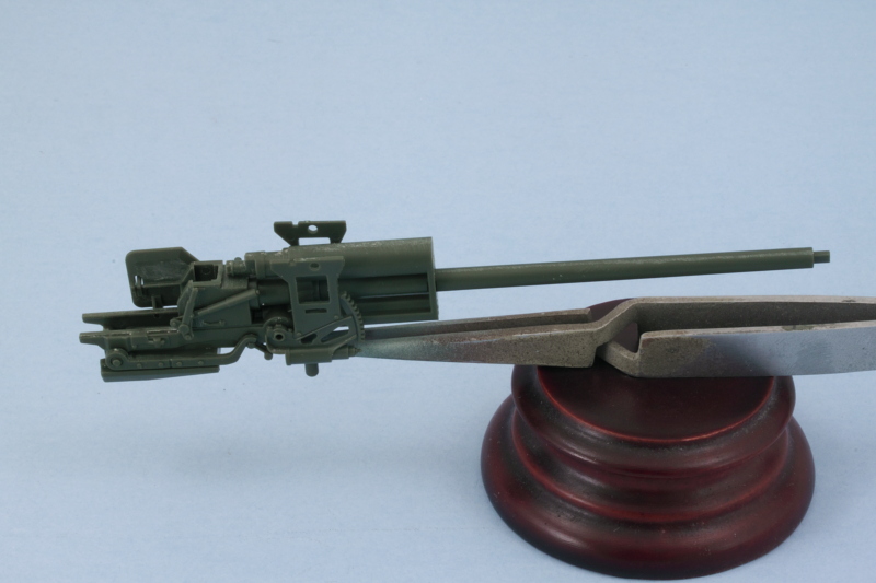


Step 29 is a fairly simple one, it adds the small support tabs for the mantlet sides as well as the elevation and traverse mechanisms along with their hand wheels. I left the wheels off for the time being to make it easier to paint the gun and its details and will add them later. It's also important to note here that the smaller wheel, C77, has to be positioned just so in order for the gunner's hand to match up with it if you plan to use the kit-supplied figures. The instructions include a little 'note direction' callout to help with this but it's not an exact thing to try to eyeball without the gunner already built to help you out. :) I also left off the gunner's sight but will add that later on. 
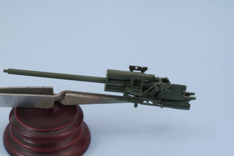


Step 30 adds the sides and top of the armored mantlet for the gun. I used a little bit of finger pressure to flex the sides in just a touch to mate up properly with the top and applied liquid glue so it would grab and create a solid join. 
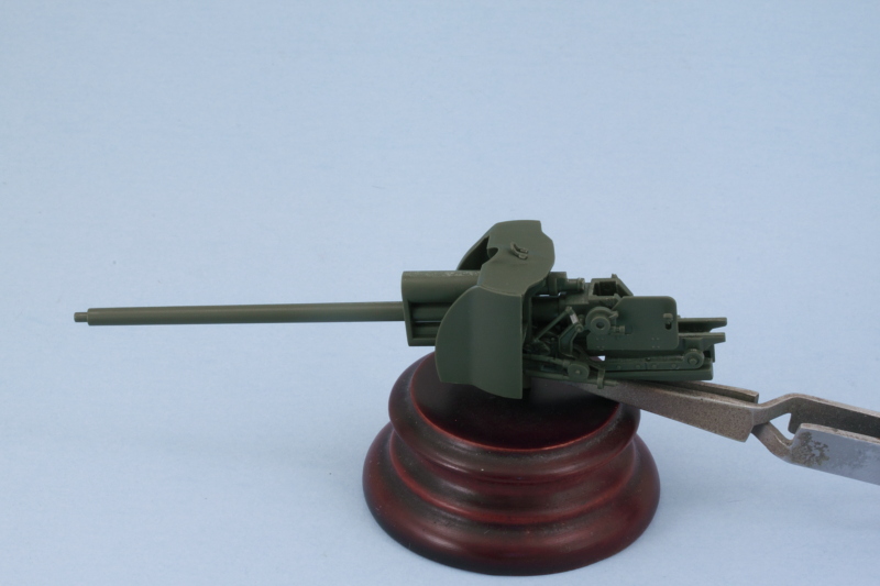


Step 31 assembles the external armored covers for the recoil mechanism and the front plate for the mantlet. I assembled the two halves of the cover first, then added the front plate, then added it all to the mantlet front plate. Just a tiny amount of putty was needed at the top to close up a small gap with the weld seam that's molded on the mantlet front plate. 
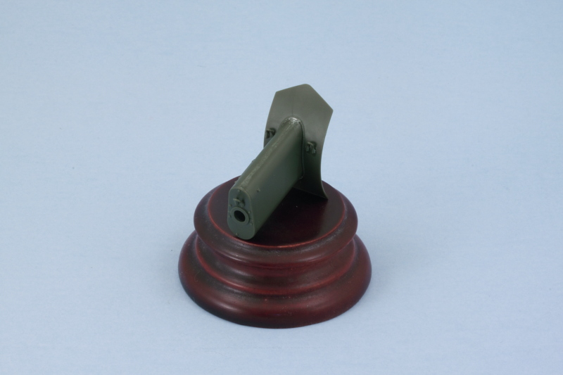


The step also calls for the assembly of the muzzle brake. This is a split-half arrangement, but careful use of liquid glue and some light sanding took care of the small join seam. The recoil cover and mantlet front aren't meant to be glued onto the gun and instead rely on a tight friction fit to keep it in place while still allowing the gun to elevate. The instructions give you a heads-up on this by clearly telling you NOT to glue the curved plate to the rest of the mantlet structure. 
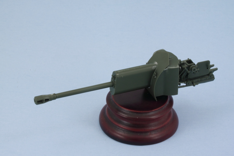


Step 33 has you install the gun into place using the polycap and that also allows you to pull the gun in and out for test fitting before committing to the final installation. Step 35 assembles the mantlet top armor that locks the gun into place out of 3 different pieces that all fit together to create the spaced plate arrangement. A quick check with the gun shows everything lining up like it should. It also showed me that I had missed one of the lifting eyes on the engine access hatch on the front hull, so that got checked off while I was at it. 
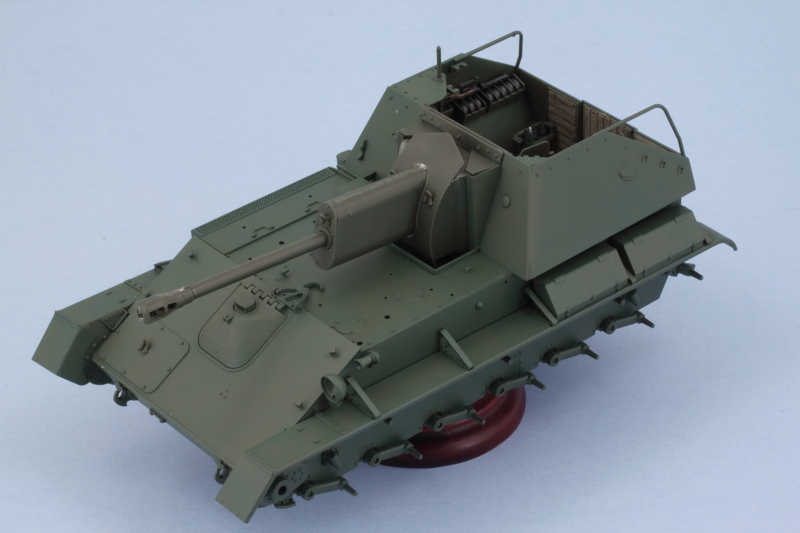


That meant it was time for paint! I airbrushed the gun assembly using the same process on the hull. 
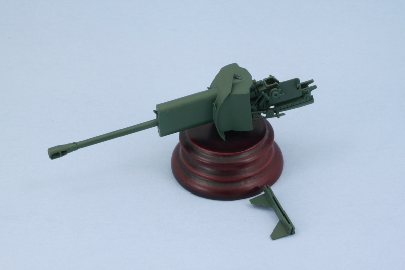


Since this was the last time I had planned to have the airbrush set up with the hull colors, I placed the gun and mantlet cover and checked for consistency. After some minor changes and adjustments, it all looks like it belongs to the same vehicle! :) 
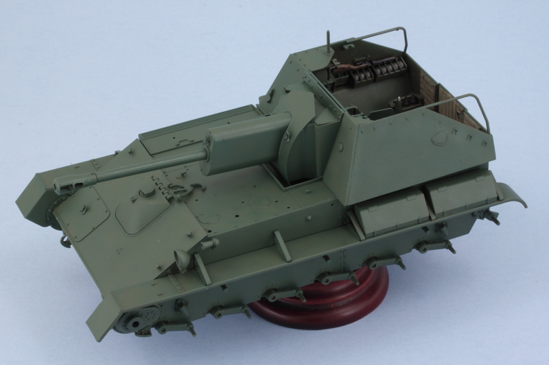


Next up will be dealing with all the hull equipment that needs to go on the main deck and other spots. 

  • Member since
    July 2004
  • From: Texas
Posted by wbill76 on Monday, March 28, 2016 7:32 PM

Hey Karl! Thanks buddy, no worries on the radio song. Big Smile Beer 

  • Member since
    January 2007
Posted by the doog on Monday, March 28, 2016 7:08 PM

Cool beans, Bill! It's all looking great, as usual!

Playing on the radio right now.... "HEY LA, HEY LA, MY BOYFRIEND'S BACK..."! Big Smile

(hey man, it's the 21st century, don't freak out, lol)

  • Member since
    July 2004
  • From: Texas
Posted by wbill76 on Monday, March 28, 2016 6:47 PM

Gamera

She's lookin' good, I love how the fighting compartment is turning out, really nice detail there. 


Thanks Gamera! Beer

  • Member since
    July 2004
  • From: Texas
Posted by wbill76 on Monday, March 28, 2016 6:46 PM

Spent some time on the hull with the airbrush today. First order of business involved masking off the fighting compartment so I could touch up things a bit and blend stuff together. I applied a base coat of MM enamel Russian Armor Green to the hull. I used some blue tack poster putty to hold the fenders in place and get an idea of where the shadowed areas would be. 


Road wheels, idlers, and sprockets got some attention as well. I airbrushed MM enamel Gunmetal for the rubber portions then used a circle template to mask the hubs. The Russian Armor Green base coat was airbrushed first followed by a 50/50 mix of OD/Russian Armor Green to get it to the desired color to go with the rest of the hull. 


Speaking of which, I used the 50/50 OD/Russian Armor Green mix to shift the color tone of the base coat and provide some variation in the overall look. This was applied at low pressure, approximately 10 psi, and working section by section up close. The fenders were popped off and worked on separately, one nice advantage to having them remain loose until after the tracks are on. 


I dry fitted the fenders and removed the masking tape from the compartment to be sure that everything was looking like it all belonged on the same vehicle. I made a couple of small adjustments in a couple spots. Here's where things stand before I start on the gun. 


Still plenty to do! 

  • Member since
    November 2009
  • From: SW Virginia
Posted by Gamera on Monday, March 28, 2016 11:35 AM

She's lookin' good, I love how the fighting compartment is turning out, really nice detail there. 

"I dream in fire but work in clay." -Arthur Machen


  • Member since
    July 2004
  • From: Texas
Posted by wbill76 on Monday, March 28, 2016 11:29 AM

Thanks Stik! I can imagine that it would be quite the improvement over the older offerings for sure! Wink Glad to have you along! Beer 

  • Member since
    July 2004
  • From: Sonora Desert
Posted by stikpusher on Sunday, March 27, 2016 9:29 PM

Very nice! Way better than the old Alan/DML kit that I tackled last year.Yes I want to see how this turns out...


F is for FIRE, That burns down the whole town!

U is for URANIUM... BOMBS!

N is for NO SURVIVORS...

       - Plankton

LSM


  • Member since
    July 2004
  • From: Texas
Posted by wbill76 on Sunday, March 27, 2016 5:39 PM

Hope everyone had a Happy Easter (for those that it applies...otherwise, Happy Sunday!) :) 


With the focus on getting the hull ready for painting, I bounced around in the instructions quite a bit hunting for stuff that I could install now vs. later. In Step 20, I added the base parts for the gun travel lock while the lock itself is added in Step 24. The lock remains movable, so that's a plus. I also added the small rectangular hood for the exhausts after a test fit showed it's possible to still add the exhaust pipe after it's in place. Step 25 had the 5 retaining hooks for the tow cable, so those were added as well. 


Over on the hull's right side, I added the large radiator/air exhaust box that's called for in Step 21. I found it easier to add the top part, B11, to the hull first since it has a large mount tab to support and align it and then add the rest of the box around it vs. assembling the box off the vehicle and installing it as a single part as the instructions call for. The top doesn't have any solid alignment guides for the 'finned' side portion and getting it lined up right is critical, hence my 'alternative' method to ensure that happened. :) I added the small canister from Step 23 and the second exhaust cover from Step 24 after again testing the exhaust pipe fit to be sure I could still install it with the cover in place. 


Now came the fenders. In order to fit the tracks onto the suspension, the fenders need to remain loose. In theory, since all of the top links are individual links, you could add them after the fenders are in place but that's an iffy proposition at best IMHO. Step 22 assembles the two fenders along with the front portions of the mud guards. 


The next trick with the fenders is getting the braces added. Instead of providing the triangular brackets as single pieces, Tamiya molded parts of the bracket on the fenders, part on the hull, and has the angled top part as a single piece that's added to complete the whole bracket. These are added in Steps 24 and 25 and this arrangement actually works out ok if you're careful. I used tape to hold the fenders in place and added the brace tops one at a time and only glued their bottom ends to the fenders themselves. the tops were adjusted so they would fit into the openings in the hull but still allow me to remove the fenders for painting and the track install. 


Once I was sure the braces would behave, I added the two storage boxes to the left fender as called out in Step 36. These boxes don't attach to the hull side and the instructions show a nice little sub-diagram that emphasizes this to avoid any mistake. I also cleaned up the headlight and siren horn as mentioned in Step 35 and installed them as directed in Step 36. 


That should put me in good shape to get the hull painted before I move on to the gun. 

  • Member since
    July 2004
  • From: Texas
Posted by wbill76 on Saturday, March 26, 2016 10:51 PM

Thanks DM! Always good to see the smiley King is still kicking around! Big Smile

  • Member since
    July 2003
  • From: On my kitchen counter top somewhere in central North Carolina.
Posted by disastermaster on Saturday, March 26, 2016 10:28 PM
 

 Bill's back......................... YAyyyyy!

 
It's the "Unexpected Bill" I'm
glad to see http://ru.wikifur.com/w/images/e/ec/%D0%9C%D0%B0%D0%B3_%D0%B8_%D0%B2%D0%BE%D0%BB%D1%88%D0%B5%D0%B1%D0%BD%D0%B8%D0%BA_(%D1%81%D0%BC%D0%B0%D0%B9%D0%BB%D0%B8%D0%BA).gifhere.


http://arcanumclub.ru/smiles/smile448.gif Looks like you still got that
magic touch too.

 https://i.imgur.com/LjRRaV1.png


  • Member since
    July 2004
  • From: Texas
Posted by wbill76 on Saturday, March 26, 2016 7:32 PM

Thanks Eric! Beer 

  • Member since
    March 2003
  • From: Rain USA, Vancouver WA
Posted by tigerman on Saturday, March 26, 2016 6:40 PM

Glad to see another wbill WIP. Missed you bud.

   http://i7.photobucket.com/albums/y269/wing_nut_5o/PANZERJAGERGB.jpg

 Eric 

  • Member since
    July 2004
  • From: Texas
Posted by wbill76 on Saturday, March 26, 2016 6:30 PM

My pleasure Hunter, appreciate the comments. Smile Beer

  • Member since
    January 2016
  • From: A Galaxy Far, Far Away
Posted by Hunter on Saturday, March 26, 2016 6:17 PM

wbill - 

The build looks great...your commentary is awesome. I'm enjoying the build and learning a lot. Thank you for sharing!

Hunter 


  • Member since
    July 2004
  • From: Texas
Posted by wbill76 on Saturday, March 26, 2016 5:25 PM

As promised, today's efforts focused on getting the suspension components installed and ready for painting. To do this, I had to go back to Step 3 and add the final drive housings along with their polycaps. I also cleaned up the 6 return rollers since they are called out in the same step, more on them later. Continuing on, Steps 13 and 15 have the 4 bump stops, two per side. That brings us to the main attraction, Step 16, which installs all swing arms and the idler mounts. Tamiya designed the swing arms to be fixed and level with each other using a small mount pin that the arms attach to. This, of course, is also designed to support their link-and-length track arrangement covered in Steps 19-20. 


While I was poking around in the steps, I went ahead and added in the driver's hatch and periscope in the closed position. The kit parts have detail on the lower part of the periscope but nothing on the inside face of the hatch or the driver's area. 


Road wheels were next under Step 17. There are 14 wheels (6 road, 1 idler per side) that have to be removed from the sprue along with a matching 14 rear hub inserts to make the full wheels. I used a sanding stick to remove the mold seam on the rubber portion of the wheels. Each of the hub inserts has 2 sprue attachment points that have to be carefully removed to keep their round shape intact, easily done with a sharp #11 blade and a little patience. 


A touch of liquid glue around the rim edges got the wheels together and I also assembled the sprockets as called for in the same step. The steel return rollers from Step 3 also had a small mold seam that was sanded down to get them cleaned up. 


After the glue had dried on the sprockets and wheels, I did a quick test fit to make sure everything sits level and plays nice with each other. As you can see, the road wheels cover almost the whole lower hull area below the fenders. These will be painted separately to allow for easier detailing and weathering before the tracks and fenders have to go on. 


Next up will be dealing with some more of the hull details and getting the fenders together so I can maximize the airbrush time for the next round of painting. 

  • Member since
    July 2004
  • From: Texas
Posted by wbill76 on Saturday, March 26, 2016 4:56 PM

Thanks Hunter, it's good to be back. Wink

Glad to have you along for the ride! Beer I always try to outline what works and what doesn't so other builders can at least know what not to do! Geeked

  • Member since
    January 2016
  • From: A Galaxy Far, Far Away
Posted by Hunter on Saturday, March 26, 2016 4:33 PM

wbill - 

Sir, your build is looking great. I am new to modeling and was informed you were an individual to watch for tips and techniques...and they were correct. Your detail and painting are dead on. Plus a great subject to build. I'll be here to the end. Also, Welcome back! Big Smile

Hunter 


  • Member since
    July 2004
  • From: Texas
Posted by wbill76 on Friday, March 25, 2016 7:32 PM

Achieved a major milestone in the build today in terms of getting the fighting compartment all together. First order of business, I decided it would be easier to paint the exterior of the compartment plates before installation. This meant adding some of the exterior details like the crew step called out in Step 18 and the radio antenna and pot called out in Step 21. Both of those parts have recessed mount points and a little bit of putty help was needed in some spots to fill those in completely before painting. 


The plates and the front of the compartment were airbrushed first with Russian Armor Green and followed up with the 50/50 OD/Russian Armor Green treatment that I used on the interior. 


I installed the rest of the communications equipment on the right side and added the large wall component into the compartment proper. While I still had the compartment open, I added some pigment weathering in the form of Mig Rubble Dust applied to the floor. 


Right side upper plate was added next along with the large top plate that includes the commander's periscopes. It has the added advantage of a larger attachment area due to the radiator box that attaches to the outside, so it was the easiest to get lined up with the front of the compartment. 


For the left side, I used regular glue along the base edge since it has the most contact surface and liquid glue at the front once it had grabbed a bit. As you can see in the photos, the greens don't all match up perfectly just yet, that will change once it's all set and I have the opportunity to go back over the join areas with the airbrush. My main concern at this point was avoiding having to do a lot of work with the full compartment masked off. 


Last but not least, the rear plate was added to complete the full compartment. Overall the fit was excellent. One small minor area on the left rear plate join needed just a touch of putty and sanding, otherwise it all went together perfectly. 


Next up will be spending some time on the suspension components and various other external details. 

JOIN OUR COMMUNITY!

Our community is FREE to join. To participate you must either login or register for an account.

SEARCH FORUMS
FREE NEWSLETTER
By signing up you may also receive reader surveys and occasional special offers. We do not sell, rent or trade our email lists. View our Privacy Policy.