OK, big update here; I can't believe how quickly and relatively easily this went. (kettledrums...) The engines are plumbed! 
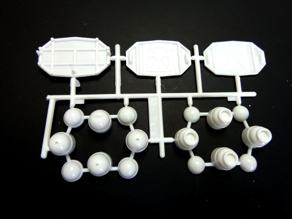
But first, I detailed the leg pod suspension things: Here's how I built them. The ParaGraphix set has parts for these, but they're mere suggestions, not really usable. I built them from:
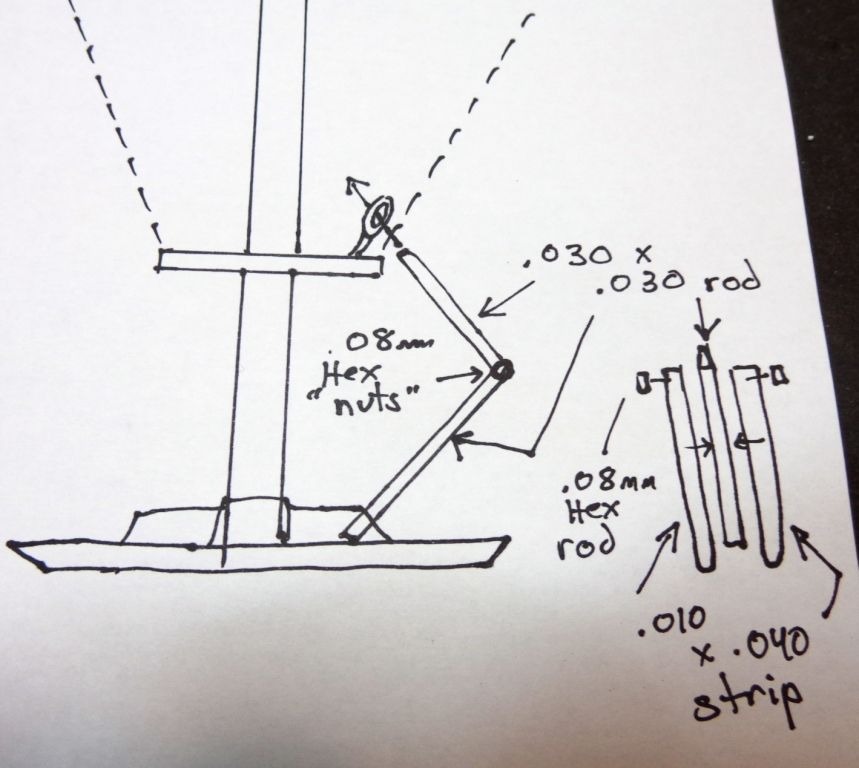
Nothing elaborate; they look the part. I also put in the connecting tabs that connect the rail to the cages from .010x.040 strip with a .030 hex rod rivet on each.
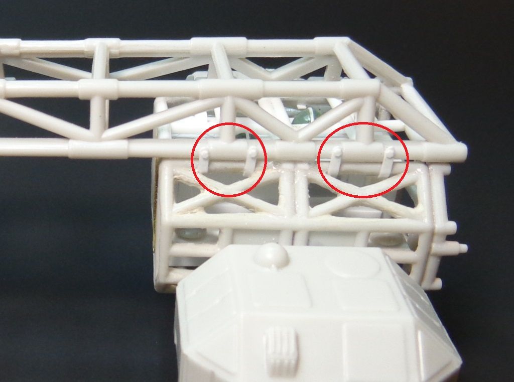
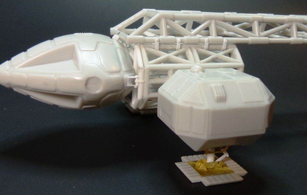
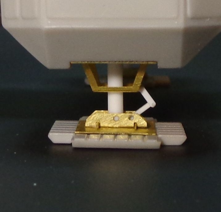
And here's the completed legs/feet.
OK, now if you know anything about this kit, you know that the engines are really simplified to the point of being awful.
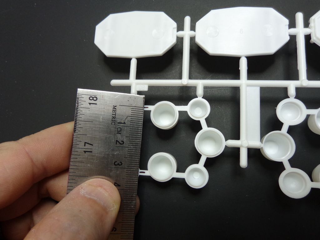
I think that the small engine "balls" are much too proud of the whole assembly; the real ones sit more "inside" of the engine circumference. Here I measure them to check....about 31.5 mms.
First things first: I cut the balls off the framework and filed the oversized rings around them. I attached the outside frame but did not attack the big nozzles yet...this will help give me better access to the work needing to be done.
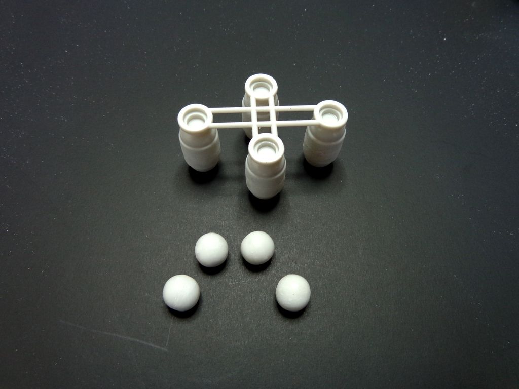
Next, I replaced the rings with .010x.030 strip. When I build my next Eagle, I will wait until I have the balls mounted properly to perform this step. It will be easier to keep them straight.
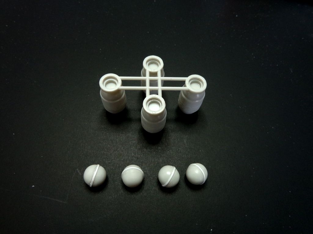
This is really where the balls ought to be.
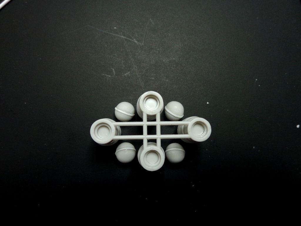
I used some old Panzer IV wheel parts to position the balls in their place, so that I could then measure their distance apart.
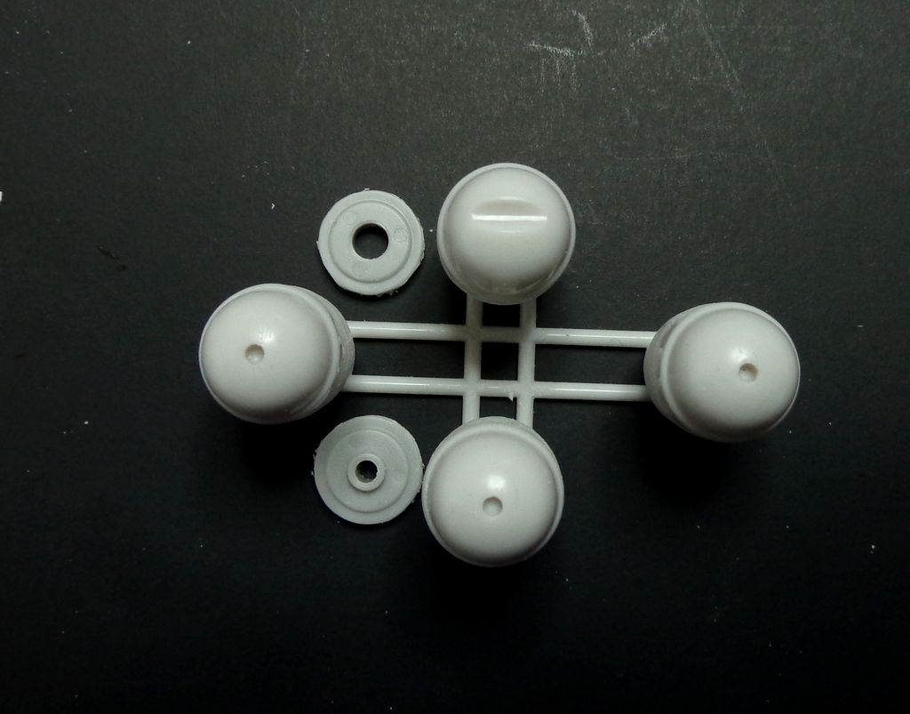
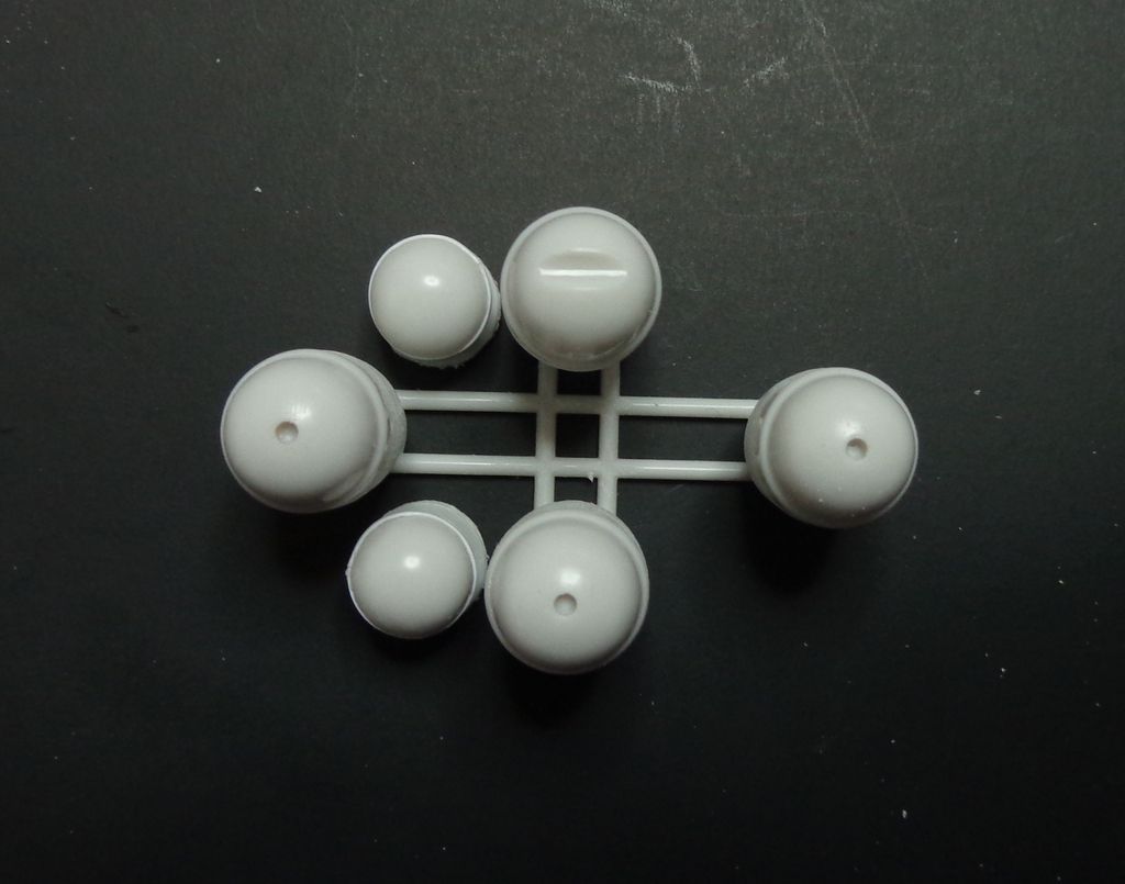 A small spot of marker on top gave me a point which to measure...about 25mm.
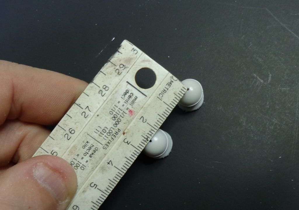
OK, call the plumber....I started by attaching the four engine pods to the frame.
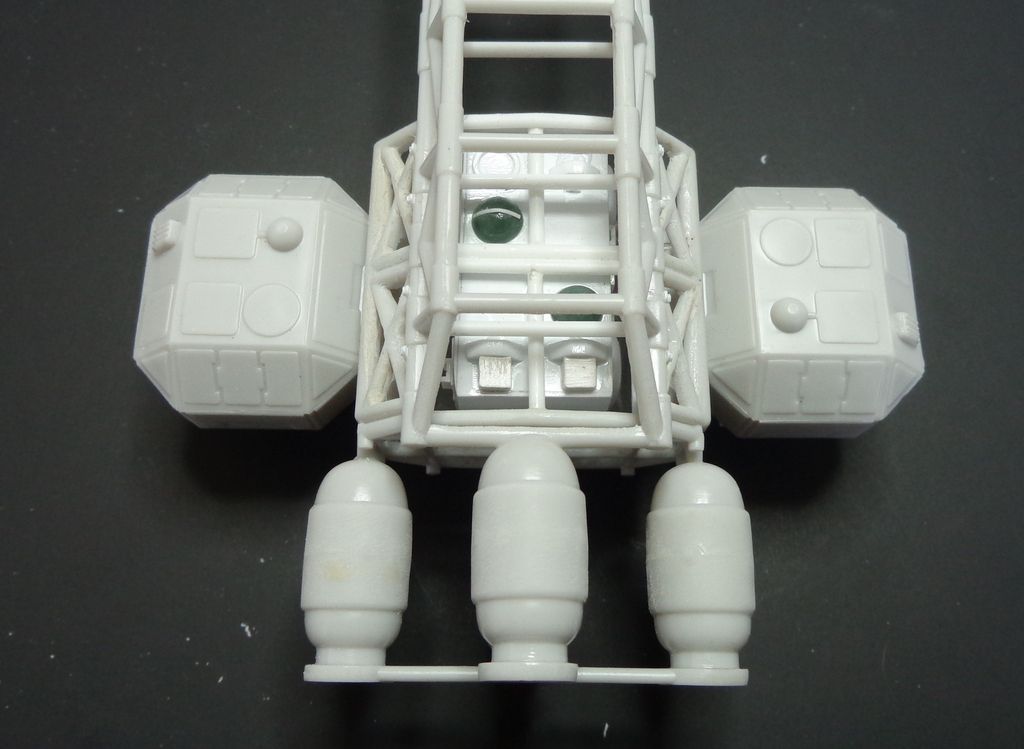
Next, I used some .080 styrene rod to add four strengthening rods inside. These are about 30.5mm long, each end has to be filed to a slant to glue flush...note the attachment points in following photos.
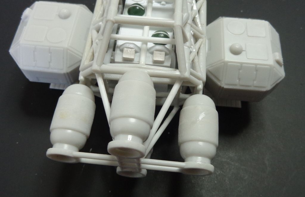
Next, I made one cylinder tube of 5/32 tube of 31.5mm and filed a groove to accept the mounting point on the upright post of the Eagle body.
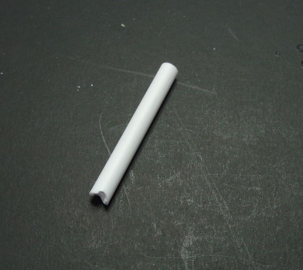
And glued that in the very middle.
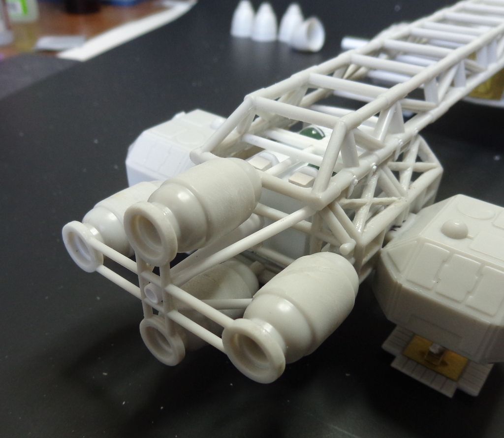
Rod placement #2. Four rod braces, 28mm each, straight back from these points. NOTE: I do not pretend that these are exact placements of measurements. They are what I could perceive to be the best possible representation from photo references within the excellent "Modelling the Eagle" publication.
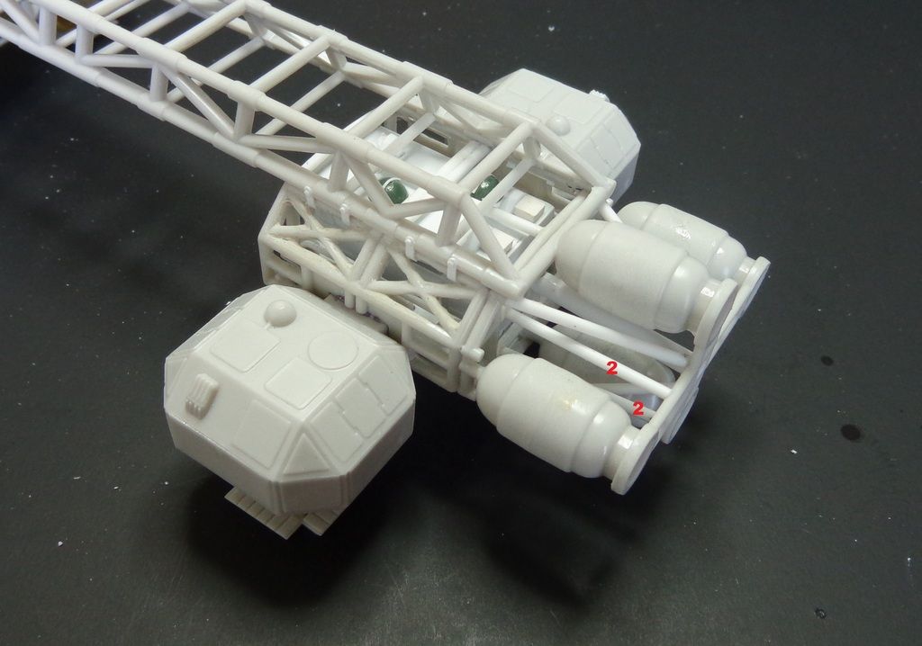
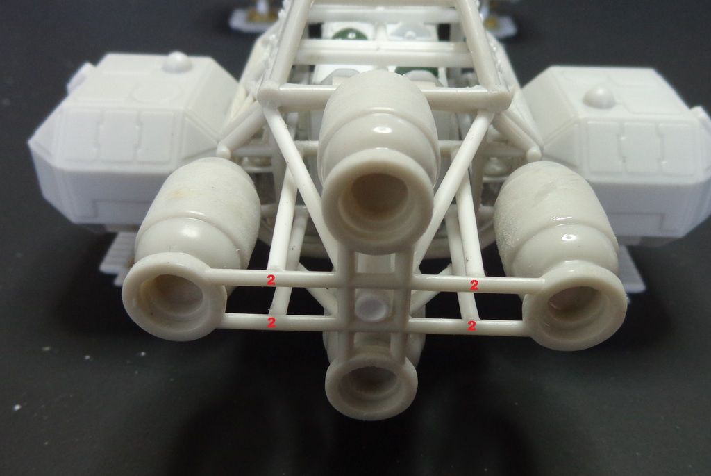
Rods #3 were tight placements---they had to be chamfered at the edges to nestle up against the #1 rods already there. These rods go down along the center rod, basically enclosing it.
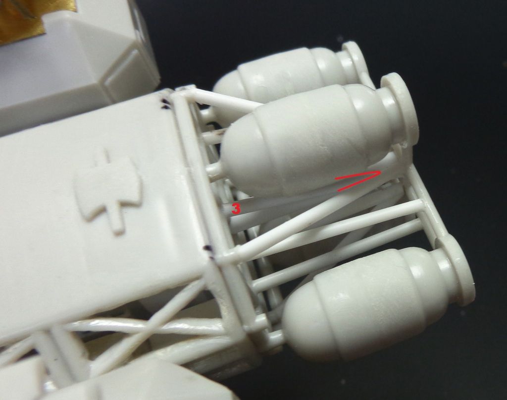
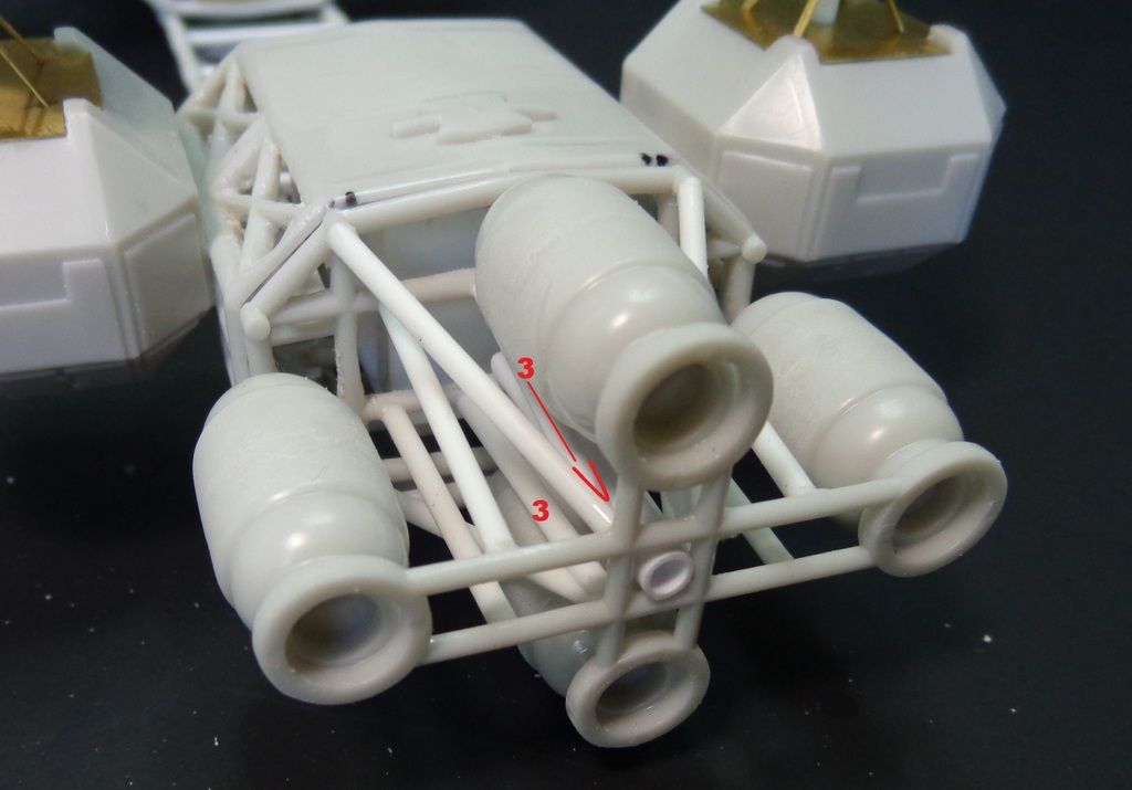
So here's how I managed to suspend/glue the balls. I had previosuly measured the distance that I liked them and made a template out of scrap stock--25.5mm. I vent the 1.5mm Raboesch Super Styrene into shape and slid the balls into them, but did not glue yet, as I have to wrangle that into the mess of tubes yet.
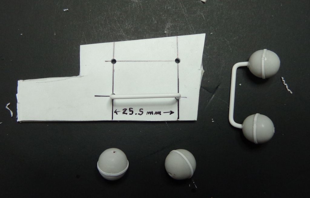
I tool one ball off, cocked the rod into the framework and then attached the other ball, gluing them. The "X" is where I would up securing the assembly to the engines. Only the rod is glued there. It tool some patient adjusting and re-adjusting to get the four balls square...
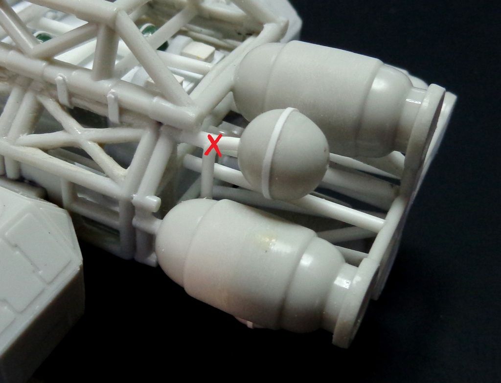
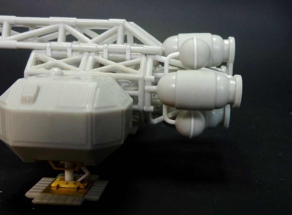
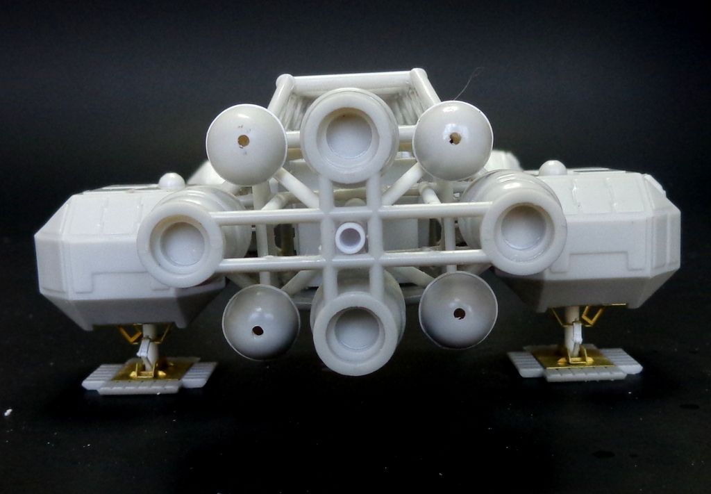
Drawing on photos in the aforementioned Eagle manual, I added the four random pipes coming off the back of the balls with Super Styrene.
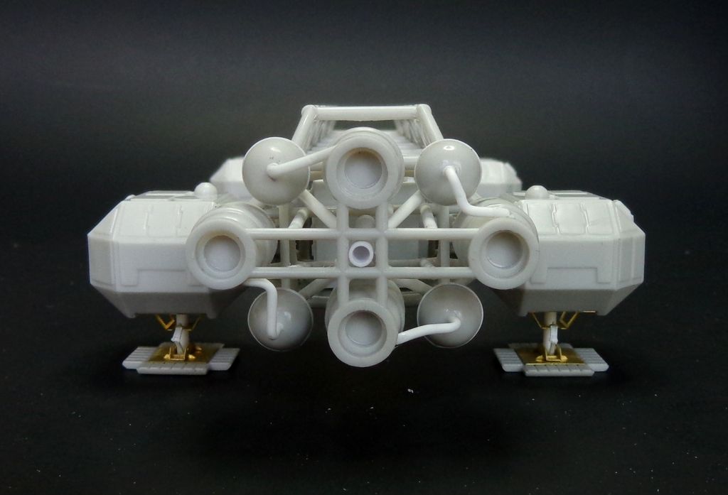
The last two pieces were these horizontal pipes on the opposite sides of the engine pods...
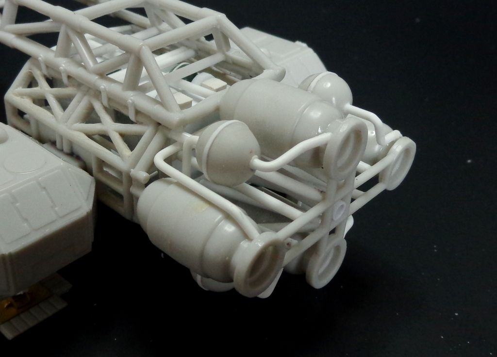
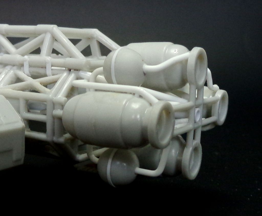
An overview...
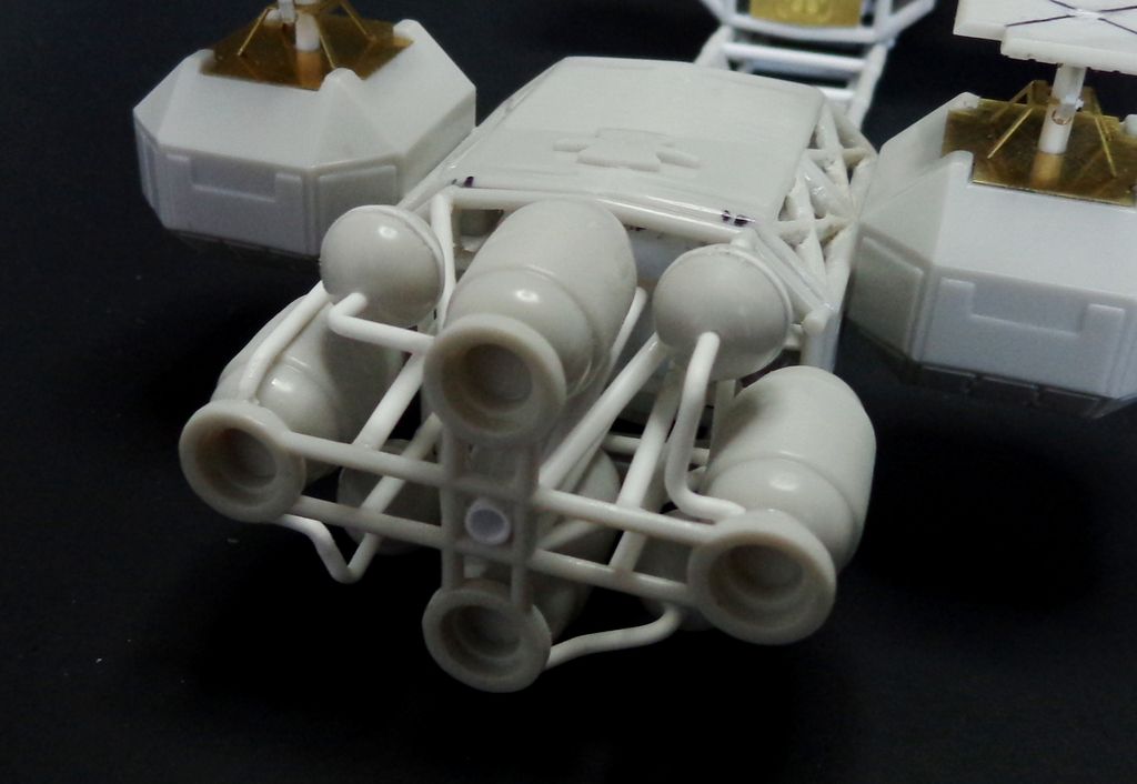
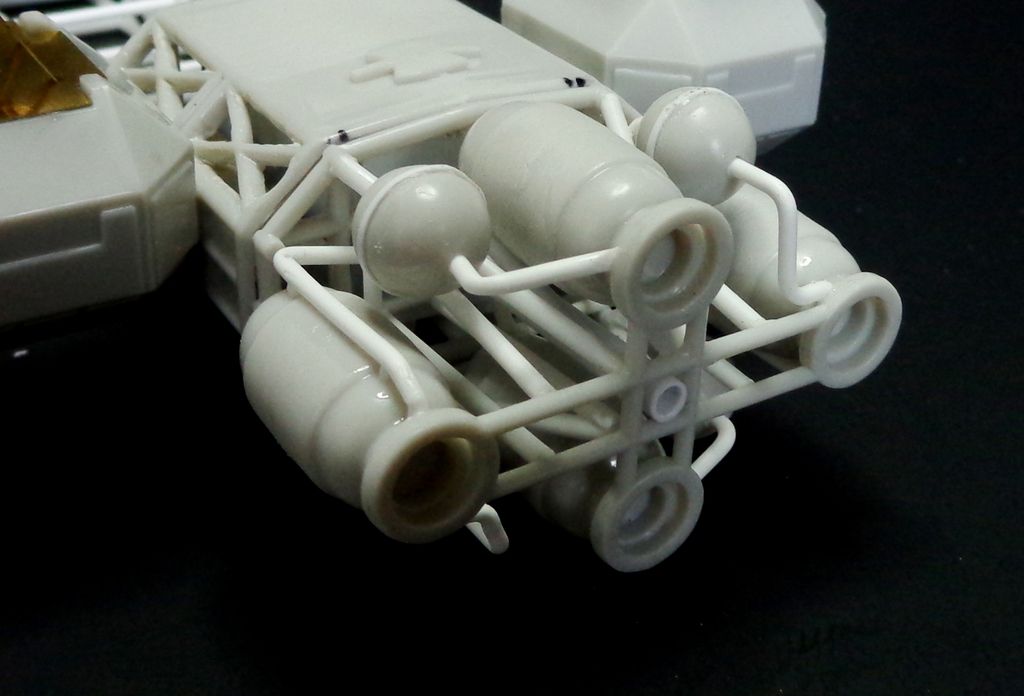
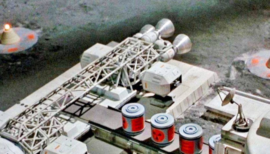
Looking at a screenshot from the show, I am pretty convinced that this is an accurate plumbing job for this particular Cargo Eagle. It doesn't have the encircling ring of later engine configurations and has those odd last four pipes coming off the rear of the balls.
Well, phew! That's it for tonight. I have to still put in the engine nozzle inserts, build the cargo pad and finish the passenger pod legs on the seperate pod display.
Thanks for looking in and all comments are welcomed!! 