SEARCH FINESCALE.COM

Enter keywords or a search phrase below:

1:72 Iowa Class Mark-7, 16"-50cal Turret #1 with Custom Interior Start-to-Finish

30093 views
270 replies
1 rating 2 rating 3 rating 4 rating 5 rating
  • Member since
    March 2012
  • From: Louisville, KY
1:72 Iowa Class Mark-7, 16"-50cal Turret #1 with Custom Interior Start-to-Finish
Posted by Builder 2010 on Tuesday, January 18, 2022 10:39 PM

This is a monster project that I've been wanting to do for years. The market had to catch up to me with the issuing of an Iowa Class 16" turret. I just viewed a box review to see what was in the kit and get a quick fix on just what I would have to make from scratch.

This is a screen print of what I saw.
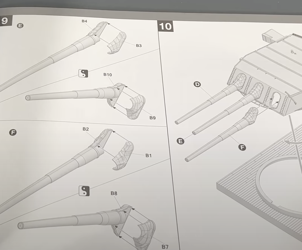
Behind the blast bags is.... nothing. That means the entire gun from the exposed part of the slide reward needs to be create along with everything else. My plan is to do the gun house interior completely including guns, gun rooms, control space with equipment, manual trainer's and pointer's stations, the big rangefinder, etc. 

I already started, assuming correctly, that nothing would be in side. I started with the gun lugs, and am buiilding the entire rear half of the guns. I am drawing all of this apparatus on SketchUp and then will 3D Print and scratch build all the rest.

Here's the gun lugs. 
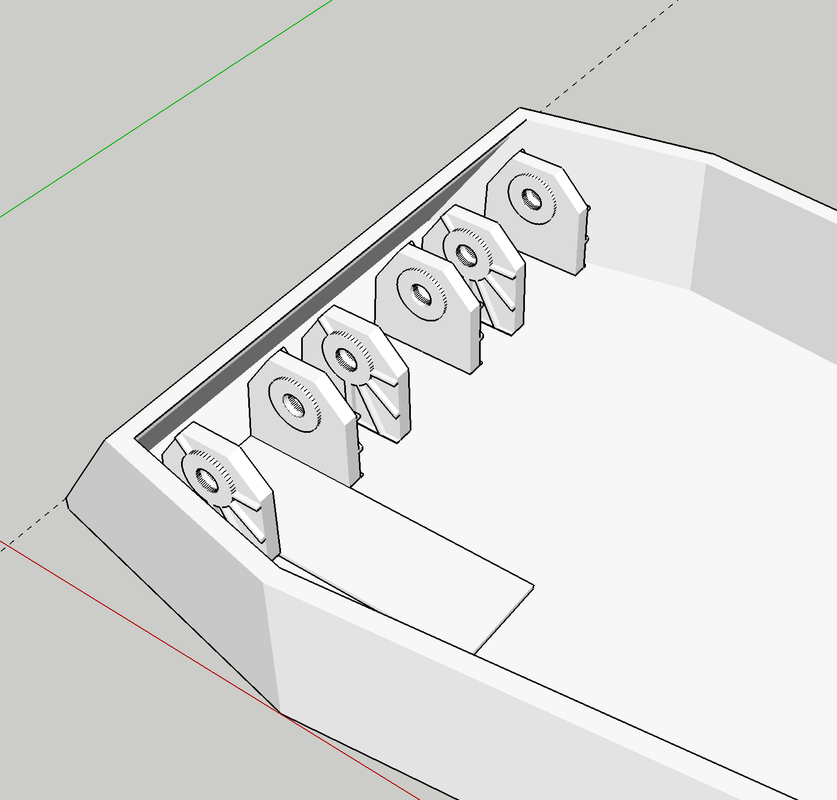
Also, I will have to thicken all the walls with material to simulate the turret armor. I have pretty good references for all of this, but no actual dimensioned blue prints. I did get from the curator of the USS New Jersey Museum Ship the actual dimensions of the rear face of the gun. With SketchUp if I can get one good measurement I can scale from that. So here's the work on the breach end.
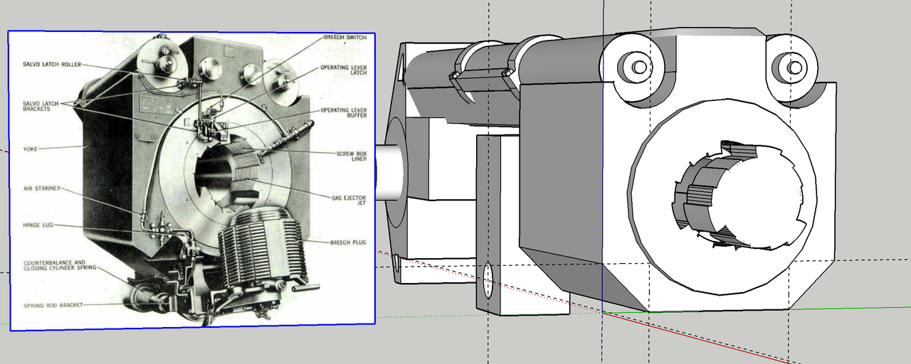
There are 20 threads in every segment of the step-thread breach. While I can make them and probably print them, I don't know if you'll see them in 1:72. It may not be worth effort.

This is going to be a massive project and will take a long time. I may not work on it continuously the whole, but as many of you who've followed my other builds on FSM and other forums, I usually finish what I start.

My initial plan is to the gun house and maybe the electric deck that lies below in the barbette. I'm not particularly interested in doing the projectile and powder flats, since there's really nothing going on. The projectile and powder lifts follow a tricky path and might present distinct challenges.
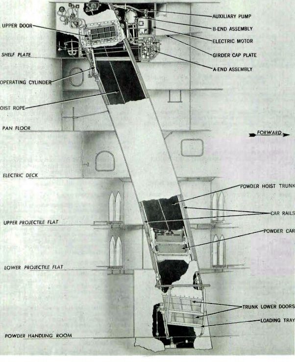
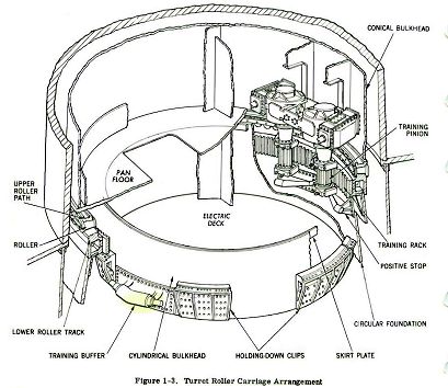
The guns are traversed by two very large pinion gears driven by hydraulic servo motors onto a massive ring gear that runs around the barbettes circumference. This ring lies well below the deck level.
Additiionally, elevation is accomplished by a very long and robust roller screw that is raised and lowered by a hydraulic ball screw that surrounds it. It's a very smooth, precise and sophisticated way to raise and lower the massive gun with little or no backlash. This compares to the pinion and sector that found on traditional artillery pieces. 
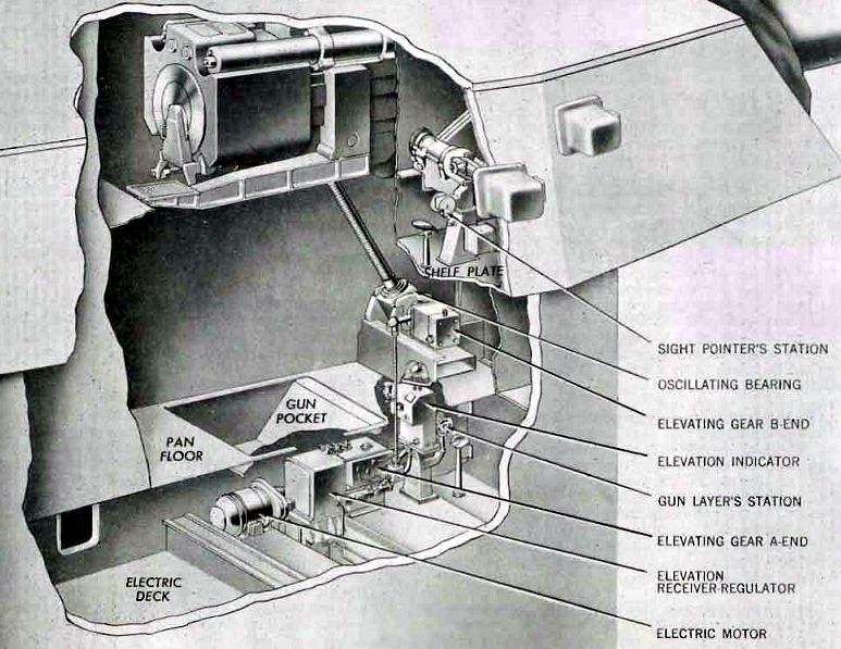
All of this equipement is energized by hydraulic servo systems with and A-end pump powered by electric motors, and the B-end hydraulic motors. These can be modeled reasonably in this scale.

Notice in the above that there were duplicate sets of manual pointing and training stations on both sides of the turret. It's what accounted for the two little housings that project out of the foreward sides of the turret. There were many ways the turrets could be aimed and fired, starting with the main radar gun directors high up in the towers. This was redundant since either director could control all three turrets. Then there was the main range finders in each turret that could also control the other two if the main directors were out of commission. Finally there were these manual stations that could aim each gun old school. These ships were meant to fight and the redundancies made sure they could under battle conditoins. It must have been weird sitting way up in those little spaces while these monsters were roaring in the room next to yours.


  • Member since
    August 2021
Posted by goldhammer88 on Tuesday, January 18, 2022 11:10 PM

Huge project, and should be a masterpiece when done.

Rather than the powder and shell flats, maybe have the outboard guns with the cradles in position with a shell on one and powder bags on the other.

Just a passing thoughts, and what you have planned is so far out of my skill set, no matter what scale, I would never think of doing.

  • Member since
    August 2019
  • From: Central Oregon
Posted by HooYah Deep Sea on Tuesday, January 18, 2022 11:53 PM

This is an awesome series; I'm just praying Takom does a 14"/50, three gun turret. To me, that would be the ultimate.

Seriously going to be watching this build; a definate 'above and beyond' kind of project.

"Why do I do this? Because the money's good, the scenery changes and they let me use explosives, okay?"

  • Member since
    May 2009
  • From: Poland
Posted by Pawel on Wednesday, January 19, 2022 1:34 AM

Hello!

This is a monster project - myself I tried to do an interior for the M60A1 Tank and I wasnät able to complete it yet... So I wish you good luck, I'll be watching!

Any idea how you are going to show everything off - and below deck, too?

Once again - good luch and thanks for sharing, have a nice day!

Paweł

All comments and critique welcomed. Thanks for your honest opinions!

www.vietnam.net.pl

  • Member since
    March 2013
Posted by LonCray on Wednesday, January 19, 2022 7:28 AM

There's only one problem:  once you build the full turret, you need to build the rest of the ship in scale around it.  

  • Member since
    March 2012
  • From: Louisville, KY
Posted by Builder 2010 on Thursday, January 20, 2022 10:30 AM

An Iowa is 887 feet divided by 72 long = 11.4 feet long. That ain't happening! It would not get out of the basement and it would resemble Jethro Gibbs perenial boat-building projects in the fully enclosed basement on NCIS. It's a great running gag!

Besides, I'm gonna be 77 this year and probably wouldn't live long enough to finish anything like that. I even have my doubts about this project. You never know...

I've started building this beast in my mind and will probably build many aspects many times over before I cut the first piece of styrene.

  • Member since
    August 2019
  • From: Central Oregon
Posted by HooYah Deep Sea on Thursday, January 20, 2022 2:51 PM

Know exactly what you mean. When I was first considering my 'Nam era ATC river boat, I was looking at GI Joe scale (1/6). Then I realized that the boat would be 9-1/2 feet long, and require it's own trailer .  .  .

I went to 1/12 scale instead and was happy with only 57 inches long!

"Why do I do this? Because the money's good, the scenery changes and they let me use explosives, okay?"

  • Member since
    September 2012
Posted by GMorrison on Thursday, January 20, 2022 5:32 PM

Well that's quite a project. You should absolutely check every part from the kit for scale based on what sources are available. 90% of the thing will be scratchbuilt, so it's not worth the risk if the rest is incorrect. The fronts were 17" over 2.5", total of which at scale is a good 1/4" plus.


IIRC from my tour, the corners are finger joined (big fingers).


Bill

 Modeling is an excuse to buy books.


  • Member since
    October 2004
  • From: Orlando, Florida
Posted by ikar01 on Thursday, January 20, 2022 9:37 PM

Good luck on that one.  I never got to see the Jersey but have seen very large ammo on pallets at Picatinny Arsenal when I usd to go home on leave between assignments and it was payday.

If this works out you could start selling detail sets for the various turret kits.  There would probably be a market for them.

  • Member since
    March 2012
  • From: Louisville, KY
Posted by Builder 2010 on Friday, January 21, 2022 9:26 PM

Drawing continues. I finally figured out how to shape the slide casting (forgining). It was hard to figure just what the shapes really were. With that done, I was able to get the basics of the back end roughed out. There's still a bunch of finer details needed to get it just right. But the hard stuff on this major component is complete.

I fit the guns into the gun lugs on the turret that I drew. I don't actually have to print the turret since it's really the only thing that's in the kit. But I wanted to get an idea if my scale was right. The guns dropped into the trunions perfectly so I'm comfortable with the widths. Remember: If it fits in the drawing, the printed parts will be exactly the same.

I pivoted them to make the cutouts by interfacing the turret front face with the gun barrels in both depressed and 45 degree elevation and then cut out the marked areas.

I'm really looking forward to doing the detail work around the breach. I will need to draw all of the gun house walls to fit all the apparatus into them. I'm actually going to model the rotating portion of the #1 turret. What's going on below is also a major amount of work.

My printer is big enough to print the breach end from the trunion to the yoke as a single piece.

And now for some news: The curator of the USS New Jersey Museum Ship said they would display the model when it's complete. He also granted my wish to see parts of the turret that are not open to the public for purposes of creating a better model.

  • Member since
    October 2004
  • From: Orlando, Florida
Posted by ikar01 on Friday, January 21, 2022 11:39 PM

That's great, you got lucky they allowed you  to do that.  I always wanted to see that boat but it was still being used the last time I was in Jersey at my Father's place.

Good luck with the project.

  • Member since
    August 2019
  • From: Central Oregon
Posted by HooYah Deep Sea on Friday, January 21, 2022 11:48 PM

Atta Boy, major score on the New Jersey folks assist. Being an historian, it sometimes amazes me why some facilities don't want to help out like that, even though it's a serious win-win situation. I'm guessing that it's a information / knowledge equals power thing. but I may be a little off on that, but it sure doesn't seem so.

Anyway, like I said, Atta Boy, Well Done.

By the way, since the scale caliber for this build is .22, I'd bet that you could find some appropriate 'projectiles' in the sporting goods market. They do come in a variety of shapes and weights / sizes. one could find anything, from the big AP projectiles, down to the stubby BL&P rounds.

"Why do I do this? Because the money's good, the scenery changes and they let me use explosives, okay?"

  • Member since
    February 2018
  • From: North Carolina, USA
Posted by Model Monkey on Saturday, January 22, 2022 7:38 AM

Brilliant.

  • Member since
    March 2013
Posted by LonCray on Saturday, January 22, 2022 9:12 AM

I've toured Wisconsin and Missouri and slept aboard New Jersey (as a Scout leader).  The folks at all three were really wonderful - totally passionate about their ships.  I'm glad the Jersey folks are letting you tour the lower spaces and I look forward to seeing your model there someday!

  • Member since
    March 2012
  • From: Louisville, KY
Posted by Builder 2010 on Monday, January 24, 2022 5:35 PM

I've been to the Big J three times: a business event with the Philly Chamber of Commerce, with grandson #1, and then again with #1 and #2. I've also been to the USS Alabama where the turrets are similar. Continued to be in communication with the curator. The rangefinders were removed in all the #1 turrets during the Iowa Class modernization in the 80s. With modern fire control they're not that needed AND #1 turret rangefinders had the habit of letting in some water in heavy seas. So my tour will concentrate on turret 2 or 3 where the rangefinders still exist. The only other difference is the additional of the projectile velocity radar. That's a minor detail that I can include or leave out.

I'm able to print the entire slide assembly on my printer as one part.

This is what it would look like on the printer.

While the raft extends over the edges of the print area, it doesn't cause a problem. Notice the loader's foot rest is pointing slightly upnward. I made this change becasue these guns load at the 5 degree elevated position. I added the five degrees to the foot rest so it would be level at load position.

Continue to collect more pictures with details including the bolt patterns on the back counterweight and the top of the gun which I didn't have good information on.

Here's a great picture of just the slide isolated from the ship and the gun. I have to add that array of round rods that appear to wrap around the recoil cylinder on the bottom.

This picture shows a good view of the spanning tray and the projectile tray's base.

Lastly, here's the gun well lit showing the top surface.

 u

Notice how little clearance between the gun and the side bulkheads. It's why I have to come up with a scheme to show all the details on the sides and bottom of the guns. I will probably make either a cutaway or use acrylic walls in strategic locations.


  • Member since
    March 2012
  • From: Louisville, KY
Posted by Builder 2010 on Monday, January 31, 2022 9:42 PM

It took a lot of hours of work, but I have the actual gun fully detailed. I probably spent 4 hours just on the breech details and getting the hinging and counter-balance system arranged in correct engineering. 

I created two versions: breech closed and breech open. The handles and cams are in the correct position for each mode. The first two images are screen prints from SketchUp and the second two are Podium Rendering Engine photo-realistic outputs. Notice that the areas that are black show up as polished chrome on the renderings.

While the drawing was challenging just in the details, what made it more so was ensuring that every part was a complete solid, no backwards faces, and all parts were fully attached to the model in enough places so the print would be stable in the 1:72 scale. I want to print the entire receiver is as few pieces as possible. I think I'll print the breech assembly in the open position as a separate parts. All the rest will fit on my printer as I showed earlier in thread.

There are left- and right-hand guns since the powder hoists come up the central column of the turret. The port and center gun have their hoists back-to-back so they have their powder hoist doors on opposite walls meaning the guns are loaded from two different sides. The starboard gun loads on the right side with the powder door on its left.


I still don't have my hands on the kit or the barrels. Without them I can't get too far into the weeds of the internal structure. I know that the guns are right. I will start designing the hardware in the gun rooms themselves including the rammer (which extends into the officer compartment) and the projectile cradle and the spanning tray. Getting the guns right was the centerpiece of this whole undertaking. And in doing so gives me a boost in confidence to do the rest.

  • Member since
    August 2021
Posted by goldhammer88 on Monday, January 31, 2022 10:16 PM

You are going to have an amazing piece when you finally get it together.

Suggest it go to IPMS Nationals.  It should sweep the show, and rightly so.

  • Member since
    March 2012
  • From: Louisville, KY
Posted by Builder 2010 on Tuesday, February 1, 2022 9:40 AM

I hadn't even considered that. That's what I need... more stress! But thanks!


  • Member since
    March 2012
  • From: Louisville, KY
Posted by Builder 2010 on Thursday, February 3, 2022 10:50 AM

Work continues...

Rammer detailing is almost done. Got some great references for the cradle and spanning tray which will be up next

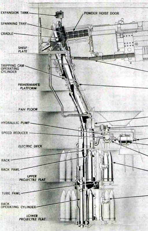
Got a good start on all the decking below the turret. Right now I've inadvertantly drawn down to the 2nd projectile flat. I may not go down that far. But here it is with the roller track in place. The turret and machinery spaces rotate with the turret and are supported by the rollers. The two projectile flats below them only have a rotating ring that moves with the turret so the projectile hoists would keep in line with their respective guns. The center column rotates which has the powder hoist chases. These go up the center column as clearly seen in this image from the Summerall Missouri Book.

The humans in the picture show the size of the ring gear. You can see the rollers under the tarpaulin. The powder hoist trunks are in the central column. The shell hoists are not installed in this picture. The heavy wedges lying against the walls are the clamps that go under the ring gear that prevents the turret from ever falling off the ship (as if that could happen).

Here's what I've got so far. The shells are to scale. The gaps between the stationary and rotating parts is exaggerated in my version. I will adjust all this when actually building the model. The big parts will be made "old school" with styrene and acrylic sheet. I will print the tapered rollers though. The ring gear will go around the upper-inner perimeter. That will be printed in segments just like the real deal due to size limitations of my printer.

A lot of the round parts could be laser cut... either out of clear acrylic or MDF. I have access to U 0f L's Maker's space and they have terrific laser cutters for public use. It's been closed due to the latest COVID surge, but that will end and I'll be taking advantage of it for this and other projects in the works.

  • Member since
    March 2012
  • From: Louisville, KY
Posted by Builder 2010 on Tuesday, February 8, 2022 10:31 PM

Drawing continues feverishly. I finished detailing the major components of the gun loading system in the gun house itself. This includes the rammer machinery which exists in the officers' compartment at the rear and the cradle and spaning tray. The latter captures the 16" projectile coming up from the projectile hoist, rotates it to the loading angle of 5°, and with the cradle and spanning tray provides a smooth surface to slide the projectile and the 6 powder bags that follow into the gun's receiver.

Drawing the cradle involved all of my SU skills and a new extension, "Truebend". TrueBend enabled me to wrap the rib pattern around the barrels of the cradle and spanning tray. There were a lot of mechanical relationships that had to be figured so the cradle would fold in the proper way. At 1/72, I'll be lucky if it prints at all let alone actually articulate, but I wanted it to be mechanically accurate. 

This is the loading position. Remember: there will be bulkheads on all sides of the guns separating them from each other and the officers' space. The rammer machinery is outside of the gun chamber with the rammer chain going through the wall.

Here's the firing position.

The singluarly most difficult part of this whole part of the project was figuring out just what was happening with the spanning tray control link and how it attaches to the tray. I had one picture on which to rely and it was ambiguous. My first attempt was completely wrong. The arm had to be far enough away from the unit to clear the main pivot bearing, but I couldn't quite understand just what was happening.

The part in question is the light color shape next to the gun captain's elbow. It looks like it's sticking straight out from the tray, but its actually first dropping down and then projecting outward. Because the tray is angled in the process of flattening out, you're looking as much at its end as it's top. The big hinge is at the bottom of the spanning tray. Because of all this angularity and perspective I wasn't able to trace the shape as I do with other objects. 

Here's a view of what I drew. It's still not perfect, but I'm not sure how to make it better with just his one image.

The real question I have is just what will print successfully at 1/72nd? A lot of the details I've drawn may not reproduce such as the hex-headed bolts.

  • Member since
    April 2003
  • From: USA
Posted by keavdog on Tuesday, February 8, 2022 10:52 PM

This thread inspired me to watch a few youtube videos on these big guns.  Crazy close quarters and tiny hatches.  These things look gigantic from the outside.  I recall touring the USS Pampanito in SF (Balao class sub) and was floored by how tight/tiny things are.  Same when I did a walk thru on a B-17.  Brave men with zero claustrophobia!

Great progress.

Thanks,

John

  • Member since
    March 2012
  • From: Louisville, KY
Posted by Builder 2010 on Friday, February 11, 2022 10:07 AM

For some reason the FSM forums were off line yesterday. Thankfully, today, they're working again.

I've finished the detailing of the gun loading equipment and started working on the bulkheads and other machinery in the gun house itself. I was able to do a pretty close job on the powder doors after finding another good diagram. Here's some status shots. Remember, the turret walls will be from the kit.

And a rendering of same…


I have to figure as I go on just what walls will be cutaway, or transparent to show all the cool stuff that going on inside. For example the machinery that runs the powder hoist is an elaborate electric driven A end/B end hydraulic hoist system that's located on the gun house floors between the bulkheads behind in front of the powder hoist chase. In fact, almost all the systems that run the turret are similar electro-hydraulic system with a motor-pump and remote actuator. This includes the traverse, elevation, and all the various hoists. I plan on detailing as many as I can.

  • Member since
    November 2005
  • From: Formerly Bryan, now Arlington, Texas
Posted by CapnMac82 on Friday, February 11, 2022 11:19 AM

Ryan, over at Battleship New Jersy is pretty responsive to comments on the YoutTube channel.

They also have some cool video from the turrets.

That beign said, Iowa recently had a video of them lowering--manually--one of he guns, which has extensive video of the inside of the gun house and the side walls.

  • Member since
    March 2012
  • From: Louisville, KY
Posted by Builder 2010 on Thursday, February 24, 2022 8:29 PM

Neither can I. I’m still waiting for the darn kit and guns to arrive at the hobby shop. It could be built without the kit at this point since I’m detailing so much of the stuff the kit has as well as all the stuff that isn’t. Earlier this week I got the lead screw elevating gear drawn. I found a good lead screw on the SketchUp 3D Warehouse and elarged it to be battleship-sized.

Today I finished up the traversing gear. This includes the B-end motor and gear boxes on the pan deck and the action ring and pinion gears protruding from the electric deck. My pinion and gear set has bigger teeth since it has to be able print in 1:72. And just for fun I figured out how to make rifling in the big guns.

Next up is a massive amount of equipment on the electric deck and finishing up the detailing the main gun houses. Interestingly, there was a manned station on the electric deck with a hand wheel a la those found on 40mm quad emplacements. These were manual stations to elevate the guns. There were three stations, one for each barrel. In the recent video “Raising the Iowa’s Guns”, the mechanics were using pipe wrenches on the shaft that goes to a bevel gear in the coupling between the elevating nut housing and the hydraulic motor. It was very slow going, but one deck below is the station with hand wheels to crank the guns up and down when the hydraulics were unavailable. It had to be a rough job to hold, sitting in a compartment with a load of electro/hydraulic machinery running and basically doing nothing unless something is not working.

Here's a view from below show the traverse pinions. As I said, mine are a bigger diameter and larger tooth design than the prototypes. The teeth at the scale the model will be are too small for successful printing and eventual use. It thought drawing the gears would be difficult, especially the ring gear. I have a SU externsion to draw volute gears. To draw the ring gear I drew and external gear of the same diameter as I wanted and used it to "cut" the ring teeth by using the INTERSECT FACES selection to embed the teeth shapes into the ring gear blank. I then pulled it to the thickness I needed. I used the same pitch size for the pinion gears. I had to experiment to get the right diameter to mesh correctly.

And using the same technique I was able to create the rifling. This time, I used the actual rifling count (96) to create a ring gear, pulled it to make it deeper and then added the twist. Was really easy.

  • Member since
    January 2015
Posted by TheMongoose on Sunday, February 27, 2022 8:06 AM

wow stupendous work! I'm learning alot reading your thread. You really are going to have a salable product when you're done. No need to wait on the kit lol

you are the future of modeling in this hobby! 

In the pattern: Scale Shipyard's 1/48 Balao Class Sub! leaning out the list...NOT! Ha, added to it again - Viper MkVii, 1/32 THUD & F-15J plus a weekend madness build!

  • Member since
    October 2019
  • From: New Braunfels, Texas
Posted by Tanker-Builder on Sunday, February 27, 2022 12:18 PM

Hi;

      May I humbly suggest the following. For the port or starboard half use The Clear sheet obtained from C.D. boxes. That way we can see all your hard work. You can use .010 for the round parts. jus'thinkin?

  • Member since
    March 2012
  • From: Louisville, KY
Posted by Builder 2010 on Sunday, February 27, 2022 12:32 PM

Thank you very much. I'm encouraged by the reaction of my followers. 

Good suggestions. I'm leaning towards 1/8" clear acrylic due to it's flatness and optical clarity. For the rotating lower parts, a cutaway may be used along with the transparent parts. The building is going to be as complex as the drawing, I'm afraid.

I got some more images of the floor area in the officer's compartment from Ryan the Curator. It turns out that the reason it was ambiguous (to me) was the flooring plates are removable so they can get to the buried ramming machinery. It was the buried rammers that didn't make any sense to me. The floor is supported on some legs and trusses. It's pretty deep and it has four steps to get to the operating level. Here's how I interpret it. The rammer is exposed in the trough from the entry hatch. I still think it's not completely accurate. I think the steps begin closer to that bulkhead. Unfortunately, their location is not shown on any floor plan I've seen.

While there is more and more wiring and piping that can be added, I have to keep in mind that we're printing in 1:72. If it was 1:48 or 1:35, it would be a whole different deal.


Onward and upward.


  • Member since
    November 2005
  • From: Formerly Bryan, now Arlington, Texas
Posted by CapnMac82 on Sunday, February 27, 2022 1:01 PM

Builder 2010
Good suggestions. I'm leaning towards 1/8" clear acrylic due to it's flatness and optical clarity.

Another benefit, 1/8" clear material scales to a 9 thickness, to give a sense of the construction of the turrets.  3/16" would be 13.5" in scale--but finding the good optically-clear material will be harder.

Having the clear parts almost suggests a diagonal "cut" of them, more like a cut-away drawing or "x-ray" sort of view.  But, that introduces a level of complexity probably not wanted for this project.

This point in the process is probably where a decision about "which" Iowa turret to model.  New Jersey did not have the elaborate ventilation systems of her sisters (Nissouri with the most complicated batch of ducts and vents; Iowa's scabed on as a refit)

I suspect that ther ewill be a bit of a hiccup when the kit parts actually arrive and fail to reach the present level of SU-modeled detail.  The Bruno and Yamato turret kits have been interesting to watch being built as they are largely "outsides" only kits.

  • Member since
    March 2012
  • From: Louisville, KY
Posted by Builder 2010 on Saturday, March 5, 2022 1:04 PM

All good points. I too was thinking that the acrylic could simulate the armor nicely. There's a good source of it in Louisville. They might even cut it for me. I could also laser cut it at the University of Louisville's public access First Build Maker's Shop sponsored by GE Appliances. They were closed during COVID, but have since re-opened.

The kit is just the exterior and is the usual styrene thickness. It's why I can really finalize a lot of this until I have the actual interior measurements of the kit. At the rate I'm going, I may not even need the kit. That could enable me to enlarge the scale a bit (1/64"?). I would have to have the barrels turned in a machine shop (or the maker's space since they have a complete industrial machine shop there.).

The kit is the WW2 Missori turret #1. All the Iowas had their #1 range finders removed in the '86 refit. It's the only one with the little railings on the roof. I will have to base my visit to the USS NJ in April on either turret #3 or 2 which still have their range finders. Not sure what to do will all the ventilation gear since none of my drawings show much of it.

Since the SU drawing is 1:1 scale, all scaling is done when I export the STL files for 3D printing.

I just spent two days building the support system for the massive range finder tube. My first attempts where what my mind's eye "Thought" was the shape of the parts. I was completely off! I erased it all and went at it again. This time it's pretty close. Having no real-world measurements or working drawings with dimension, the whole deal is a giant SWAG (simple wild ass guess). The support system is much more complex than I originally envisioned.

All the rolling surface are bronze or brass.

I'm getting pretty good at drawing sector and pinion gears. The gear teeth on the prototype are probably half the size and twice the tooth count, but I'm always thinking about what will reproduce in 1/72 on my 3D printer. I'm thinking of printing the enitre range finder in two parts mating in the center. All depends on how I can support the parts in the machine.

There's still more to do on this part. I have to put in the three operating stations with their handwheels and optical sights. There needs to be a way to operate that pinion also. And then there's the outer ends with the optics, weather seal and outer gates and their controls.

  • Member since
    November 2005
  • From: Formerly Bryan, now Arlington, Texas
Posted by CapnMac82 on Sunday, March 6, 2022 2:01 PM

Several imortant things brought up there.

Having to decide not only which ship, which turret, but having to select a time frame as well.

Scale is another.  Going away from 1/72 means having to eschew easy-to-find firgures for scale.  But, being able to "see" the detail matters, too.

Turning metal barrels at 1/64 may get interesting.  The quarter-inch ID probably "hitting" available tube stock diameters, but you may run into issues with having ehough tube thickness to get the contour in.  And having to "make up" the thickness with telescoping tubing can be an issue for turning later. 

Turning from soid stock possible, certainly, but getting that 0.25" bore through 12.5" of stock will be a delicate task on the lathe after getting the contour in to scale (and leaving enough room to get 3d printed rifling in, too--as button or star rifling cutters, to scale is a bit boggling).

Which brings up the prospect of simply ("simply" o_O) printing the barrels.  Which would want a printer with a 320-325mm distance capacity.

Hmm, just had a thought about finding a resin printer and using clear resin for casting some of these parts.  Last thing this project needs is more complexity Smile

JOIN OUR COMMUNITY!

Our community is FREE to join. To participate you must either login or register for an account.

SEARCH FORUMS
FREE NEWSLETTER
By signing up you may also receive reader surveys and occasional special offers. We do not sell, rent or trade our email lists. View our Privacy Policy.