SEARCH FINESCALE.COM

Enter keywords or a search phrase below:

Regarding T2 tankers

67838 views
183 replies
1 rating 2 rating 3 rating 4 rating 5 rating
  • Member since
    March 2007
  • From: Carmel, CA
Posted by bondoman on Friday, March 13, 2009 5:23 PM

Here's a picture of the kit. The piping on the deck seems to generally match whats shown on the diagram, except that the lines all run separately, not into unions. The hatches on the kit match the big drawing closely, as do the bumps the valve locations. One difference which is minor is that on the diagram the hatches into the three tanks in section 9 are at the fore end, while on the drawing and the model they are aft just in front of the stern structure. Guess we need a photo. I'm planning to use N scale brake wheels as valve wheels, just need to find 28 of them! There are two in section 1, 3 each in sections 2-9 and two for the fuel oil tanks aft of 9. And then there's the vent valves...

  • Member since
    December 2005
  • From: Seattle, Colorado
Posted by onyxman on Friday, March 13, 2009 5:57 PM

Looking good! There should also be a part representing the 'manifold', where the oil first comes aboard ( or goes ashore ) into thwartship pipes. I think it's just behind the midship house, under the booms. The booms are mainly for handling the big hoses from the dock.  There should be some valve wheels right there where the hoses connect. 

Fun!

(edit) I also notice there is a little dry cargo hatch forward of the forward pumproom access trunk.

Revell did a pretty good job, considering how old these molds are.

  • Member since
    March 2007
  • From: Carmel, CA
Posted by bondoman on Friday, March 13, 2009 6:03 PM

But why do all of the pipes disappear into the aft structure? (Edit- I see that's the pump room house, which sits on top of the pump room trunk, which descends to the pump room which is in the bottom of the hull forward of the motor.)

There is a dry cargo hold forward of the first cargo tank section, and aft of the chain lockers under the capstan. It is about waterline deep. Below it there is a "deep tank". What's that for? Ballast? All of this is forward of the cofferdam. Cutaway model, anybody? Not me!

Forward of the chain lockers are ammunition stores, bosun stores, peak tanks. Aft of the rear pump access trunk are the usual engineering spaces and a peak tank over the rudder. In between is just a lot of OIL. 9 sections, 3 tanks each except for a pair at the forward end.

I'm on the hunt for deck details. I think one of the nicest features of the kit is the amount of detail on the deck- it's pretty unique and I have no intention of starting over, but it could be "accurized" a little. One thing I see in most photos is some piping at the walkway levels.

For instance the valve wheels. These look in pictures to be a wheel at the top of a 1" or 2" dia. rod/tube coming up thru the deck. The kit has a little pillar thats probably about a foot or two in dia. and since it's cast, has a noticable draft to it. If I find little wheels, I'll mount them onto a piece of wire and clip off the little pedestals. I also shaved off the plating lines on the deck as they are obviously arbitrary.

  • Member since
    December 2005
  • From: Seattle, Colorado
Posted by onyxman on Saturday, March 14, 2009 9:48 AM

Somewhere deep in my attic, if the mice haven't shredded it, is a T-2 piping diagram. But just going on memory of tankers in general:

Assuming the ship is loaded, to discharge oil the pumps in the main (after) pumproom will suck it from the main cargo tanks, through the piping system shown in my diagram above. So far the oil is traveling along the bottom of the tanks.  Now it goes through the pumps and straight up to deck level, then forward through a pipe near the catwalk until it gets to a thwartship pipe at the manifold, then away through the hose to the dock.  So that's why some of those pipes come from the after structure.

To load, I suppose it could just go the opposite direction, just bypassing the pumps. ( no shipboard pumps involved in loading) More likely it will come aboard at the manifold, travel on deck for a short distance, then go down a 'drop line' to the piping system in my diagram and then to the tanks. It's probably not legible on my diagram, but if I take a magnifying glass to the original I can see some points labeled 'filling'. Those must be the drops.

The kit shows all those pipes going into the ullage trunks. I can't see why an oil line would do that. I think it must be a vent line. In some photos I can barely see that line, but it's a much smaller diameter pipe than the kit indicates. 

The fwd deep tank is for ballast, correct. The cofferdams separate the oil cargo from the rest of the ship, in case of a leaky bulkhead. Piping at the walkway level could be for steam, fresh water, etc.

  • Member since
    March 2007
  • From: Carmel, CA
Posted by bondoman on Saturday, March 14, 2009 10:47 AM

Good info Fred. So the model needs at least the add of the main intake/discharge system, which would be the dock connections, to one big pipe on deck, to the pump room trunk houses.

If those cast on pipes are vents, they ought to go to the masts, not into the stern pump room, or just sort of end forward short of the forecastle, like they do on the kit. Did the forward pumps run on steam, I assume. Therefore the steam line along the walkway, which also powered the anchor capstan?

The skylight is over the boiler room, a level above the motor room. I suppose boiler size would vary with motor power out put, but I wonder if that would affect the size of the skylight. My ship is the smaller power, 6,000 shp. Can't wait to get the lnk back, buddy.

  • Member since
    December 2005
  • From: Seattle, Colorado
Posted by onyxman on Saturday, March 14, 2009 10:49 AM

Speaking of steam....all the deck machinery, including the anchor windlass, are steam powered. Don't want any sparky gadgets!

Edit..Ha! your questions promply addressed!

  • Member since
    December 2005
  • From: Seattle, Colorado
Posted by onyxman on Saturday, March 14, 2009 11:01 AM

Some of the cast-on pipes are oil lines, going from the pumproom to the manifold. If some of them are vents, what vents #1 tank? I don't see anything on deck there.  I wonder if any of the Smithsonian plans have this piping detail? I see 'Inboard Profile and Deck Plans' on the T-2 page, but it's hard to tell if that would have what we need. I shouldn't say 'we', this is more detail than I'm interested in getting into.

See my PM Bill.

Fred

  • Member since
    December 2005
  • From: Seattle, Colorado
Posted by onyxman on Saturday, March 14, 2009 11:10 AM

Oh, re the skylight. Just guessing here, but the different engine powers wouldn't matter to the size of the skylight as far as air supply goes, but maybe as an opening for lifting machinery in or out during repairs? Although in my experience, when that has to be done they just cut a big enough hole in the deck and weld it up again when they are done.

Apropo of nothing, but these were turbine electric drives. A steam turbine drives a generator. The electricity powers an electric motor directly connected to the propeller. The advantage is you don't need expensive reduction gears, but the amount of copper in these things must have been worth a fortune in today's prices. 

  • Member since
    December 2005
  • From: Seattle, Colorado
Posted by onyxman on Saturday, March 14, 2009 11:30 AM

Mikeym already gave us this link, which has pictures of the Smithsonian's T-2 model. Pretty good deck detail there, but this ship seems to be a little different from the Revel kit. For one thing, it has a manifold forward as well as aft of the bridge.

http://www.steelnavy.com/T2%20700.htm

Another view of a model:

http://www.aukevisser.nl/esso/id68.htm

I don't know what part number this is. I just pulled it out of my spares bag, but this looks like the manifold:

Fred


  • Member since
    March 2007
  • From: Carmel, CA
Posted by bondoman on Saturday, March 14, 2009 2:05 PM

Thanks Fred and MikeyM. The model shot Fred posted earlier of a model at a show has all of the Revell deck detail straight out of the box. Looking at it, I noticed just behind the midship structure what looks to be a rack of pipes crossways, not on my kit's deck. Oh wait- it's a separate part. off to the box, looked at the instructions- it's Part 10 "pipe and valves", and lo and behold there you posted it Fred! So that's that. Nothing forward of the bridge tho.
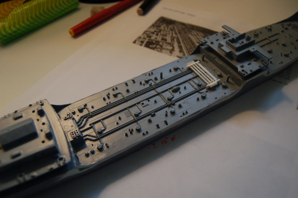
Nothing forward of the bridge tho.
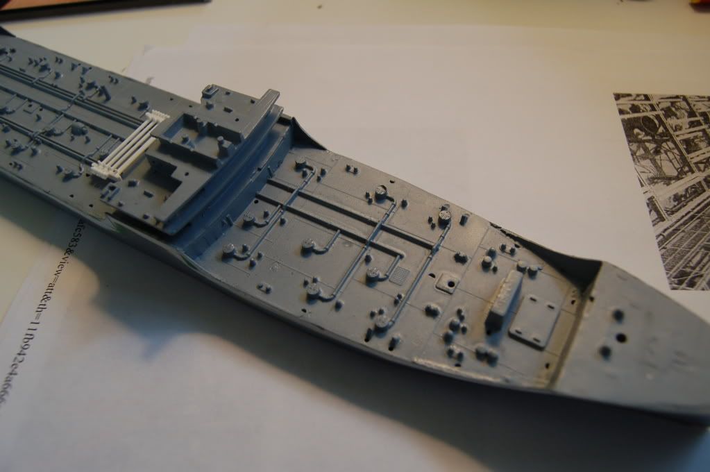
Next tho looking at the Smithsonian model on the Steelnavy link, the picture called "deck level plumbing"; worth a thousand words. There's the manifold, which has multiple connections to two sizes of pipe that run fore and aft- larger to port and smaller on the other side.

And the shot "forward deck and pilot house" which is a lot sharper than the one zoomed in. There's the forward valve manifold!!! I've spent an hour staring at these, and a pot of coffee, and I'm a little buzzyheaded, but bear with me. Open another tab and get the "deck level plumbing" pic up so that you can ref. back and forth. First, there are three big pipes crossways (athwarts, but I'm going to go off nautical here just to get it spelled out. Each has a siamese valve at each end, each of which has a valve at it's base. Each of these three larger pipes has a connection to a pipe that runs aft. The siamese valve has a side connection to a fourth valve, which runs to a smaller pipe that runs athwart, and has the same arrangement on the other side, at the other end of it's parent pipe. Each of these three smaller pipes is connected to a pipe that runs aft only from this point. Plus there's a fourth small pipe across that is connected to a pipe that runs fore and aft. The kit has three pipes cast on to port on the rear deck, which are correct, and two to starboard, which should be smaller and there should be four. Deep breath- got that. Would the larger pipes be the on/off load system and the smaller pipes the stripping system?

Then you see the smallest pipes that run from the hatches. These would appear to be the vents. On the kit they are well represented, although all three systems are the same size. When you look really closely at the way the pipes were cast, these pipes go up and onto the fore/aft pipes, but they don't really connect- they just end there. I think it was all meant to just dissappear under the walkway.

Forward of the pilot house I think I'll go ahead and use Part 10 again from the second kit, and worry about how to replace it later. There are a pair of fore/ aft pipes on the big model, and the same on the kit although they're spaced apart a few feet. They run up to the forward pump room trunk, and stop a good 50 feet short on the kit so I think I'll add extensions. Thats all for now, I need a nap!

Thanks for all the great info!

The Smithsonian tanker is a really nice model, and I'm wondering if there's one in the Maritime Museum here. I will have to go look.

To attempt to modify the kit to get this right would be futile, it actually appears much easier to scratchbuild new decks and pipes. Not this time!

My N scale valve wheel idea won't work, they're too big. I need another source of tiny round things.


  • Member since
    December 2005
  • From: Seattle, Colorado
Posted by onyxman on Saturday, March 14, 2009 2:42 PM

L'arsenal has PE handwheels in 1/350

http://www.larsenal.com/Source/catalogue/larsenal/AC_350_50.jpg

You might need more than one though.

You could slice sections from Evergreen rod.

This would be an interesting scratch build:

http://upload.wikimedia.org/wikipedia/commons/9/9c/Piping_system_on_a_chemical_tanker.jpg

Big Smile [:D]


  • Member since
    December 2005
  • From: Seattle, Colorado
Posted by onyxman on Sunday, March 15, 2009 1:04 PM

Looking through the pictures of 'Mission' tankers on Auke Visser's site, I don't see any evidence of a forward piping manifold.  Lot's of good pics here though.

http://www.aukevisser.nl/t2tanker/id171.htm


  • Member since
    December 2005
  • From: Seattle, Colorado
Posted by onyxman on Sunday, March 15, 2009 2:00 PM

Note the propped open engine room skylight panels on this T2-S-A1


  • Member since
    March 2004
  • From: Kincheloe Michigan
Posted by Mikeym_us on Sunday, March 15, 2009 2:44 PM
 onyxman wrote:

Note the propped open engine room skylight panels on this T2-S-A1


From that angle it almost looks like a 3 flapper. I think it'll be interesting to scratch a prop for holding those flaps up I think it would be a similar design for the props that hold the hood of a car up during maintenance. And it would be nice if someone finds a close up of the skylight so I can see if there are dogs on the skylight for securing the flaps I've seen them on the cargo holds of the freighters that go by at work.

On the workbench: Dragon 1/350 scale Ticonderoga class USS BunkerHill 1/720 scale Italeri USS Harry S. Truman 1/72 scale Encore Yak-6

The 71st Tactical Fighter Squadron the only Squadron to get an Air to Air kill and an Air to Ground kill in the same week with only a F-15   http://photobucket.com/albums/v332/Mikeym_us/

  • Member since
    March 2007
  • From: Carmel, CA
Posted by bondoman on Monday, March 16, 2009 2:16 AM

Looks like a smaller forward manifold. Can't quite make out the skylight, though! Brown deck, second group from the left (west).

http://maps.google.com/maps?q=Benicia,+CA&t=h&hl=en&ie=UTF8&ll=38.064328,-122.104754&spn=0.001694,0.003433&z=18

  • Member since
    November 2005
Posted by Anonymous on Monday, March 16, 2009 9:32 AM
Did these ships have two elevated bridges/housing areas because everything below deck was reserved for fuel/oil, save for the engine machinery?
  • Member since
    March 2007
  • From: Carmel, CA
Posted by bondoman on Monday, March 16, 2009 9:56 AM

One big floating oil can. Forward of the forward coffer dam, which is about where the forecastle starts, there are ballast tanks, on top of which there are cargo holds, ammunition lockers and other stores, plus the chain locker. At main deck level are shops, paint locker, lamp room.

Midships the structure is fresh water tanks at the main deck level with a lot of open pass thru, ofiicers quarters above that; captains quarters, gyro room and radio room above that; and the chart house/wheel house.

In the stern, aft of the cofferdam, which is about where the stern structure begins, there are all of the predictable engineering spaces, ballast tanks, lockers and ammunition storage. At deck level the seamen's quarters and galley stores, above that the engineer's quarters, galley and the crew and officer's mess rooms, and above that the boat deck which has a double high open space for the boiler room, which is above the engine room and directly under the skylight. I'd say the fore/aft walkways got a lot  of use.

  • Member since
    March 2004
  • From: Kincheloe Michigan
Posted by Mikeym_us on Monday, March 16, 2009 9:57 AM
 bondoman wrote:

Looks like a smaller forward manifold. Can't quite make out the skylight, though! Brown deck, second group from the left (west).

http://maps.google.com/maps?q=Benicia,+CA&t=h&hl=en&ie=UTF8&ll=38.064328,-122.104754&spn=0.001694,0.003433&z=18

I think the skylight is covered since this is the Mothball fleet remember. But just behind her in the next row is the USS Iowa.

On the workbench: Dragon 1/350 scale Ticonderoga class USS BunkerHill 1/720 scale Italeri USS Harry S. Truman 1/72 scale Encore Yak-6

The 71st Tactical Fighter Squadron the only Squadron to get an Air to Air kill and an Air to Ground kill in the same week with only a F-15   http://photobucket.com/albums/v332/Mikeym_us/

  • Member since
    March 2007
  • From: Carmel, CA
Posted by bondoman on Monday, March 16, 2009 10:04 AM
 Mikeym_us wrote:
 bondoman wrote:

Looks like a smaller forward manifold. Can't quite make out the skylight, though! Brown deck, second group from the left (west).

http://maps.google.com/maps?q=Benicia,+CA&t=h&hl=en&ie=UTF8&ll=38.064328,-122.104754&spn=0.001694,0.003433&z=18

I think the skylight is covered since this is the Mothball fleet remember. But just behind her in the next row is the USS Iowa.

True enough, and now that I stare at it that isn't a T2, or is so heavily modified as to be unrecognizable. Has a bulb bow. Fun exercise though, huh? I think that's my buddy Bruce in a duck blind on the shore...
  • Member since
    November 2005
Posted by Anonymous on Monday, March 16, 2009 10:33 AM
 bondoman wrote:

One big floating oil can. Forward of the forward coffer dam, which is about where the forecastle starts, there are ballast tanks, on top of which there are cargo holds, ammunition lockers and other stores, plus the chain locker. At main deck level are shops, paint locker, lamp room.

Midships the structure is fresh water tanks at the main deck level with a lot of open pass thru, ofiicers quarters above that; captains quarters, gyro room and radio room above that; and the chart house/wheel house.

In the stern, aft of the cofferdam, which is about where the stern structure begins, there are all of the predictable engineering spaces, ballast tanks, lockers and ammunition storage. At deck level the seamen's quarters and galley stores, above that the engineer's quarters, galley and the crew and officer's mess rooms, and above that the boat deck which has a double high open space for the boiler room, which is above the engine room and directly under the skylight. I'd say the fore/aft walkways got a lot  of use.

Wow...there doesn't seemn to be much space left for oil!!!!!!!!!!!!!
  • Member since
    December 2005
  • From: Seattle, Colorado
Posted by onyxman on Monday, March 16, 2009 10:41 AM

Turns out I had this in my collection all along. It's snipped from a pic I have of the Ideal-X formerly Potrero Hills.

Sorry it's so small, but it looks like three flaps on each side and shows how much smaller the skylight is compared to the kit's.

 This shows the profile plan of a T-2 with all the compartments:

http://www.aukevisser.nl/t2tanker/id492.htm


  • Member since
    March 2007
  • From: Carmel, CA
Posted by bondoman on Monday, March 16, 2009 11:00 AM

Here's a photo of the Hat Creek.

Now to find details. I would guess these would be kind of hard to access from below!

A task to measure the dimensions of the skylight has revealed a fundamental error in the model!

At the stern, on the boat deck level, the forward cabin bulkhead is more or less directly above the bulkhead on the poop deck. The cabin width is only slightly less than the one below. The 20mm gun tubs sit right on the upper deck. This does not at all compare to any pictures I can find. The cabin on the boat deck is narrower forward of the stack than athwart the funnel, while on the model it grows WIDER. The problem is two-fold: one the gun tubs should be an independent tower (which is an open truss!!!) each accessed by a catwalk from the gun (?) deck, and two the skylight is way over sized in every direction and sits in the middle of a deck that is way too wide and deep! Also there's a shack at the stern end of the cabin that I can't find in photos. This will be very hard to fix and I'm going to think about it for a while. The big problem is that the way the decks are molded, surgery is gonna be drastic and ugly. But it does answer a visual problem I've had looking at this kit- the stern house with it's neat wedding cake stack just looks too modern, and wrong. The real thing is a pretty busy area. Oh dear!

But to the problem at hand. The kit skylight measures 16 ft. wide by 26 ft. long. The drawing shows 8 ft. by 16 ft. I'd say the location is about right, on center.


  • Member since
    December 2005
  • From: Seattle, Colorado
Posted by onyxman on Monday, March 16, 2009 12:11 PM

Yes, I have noticed the difference in the shape of the after house between the kit and some of the photos, particularly that off-center shack aft of the stack. I wonder if it was changed post construction, or maybe there was a variation in some of the yards.

Let me post this again:

And now the kit, with the size of the skylight unmodified:

In this case the photo of the real ship shows the space aft of the stack was filled in to the frame of the aft part of the off-center shack. In other photos I notice the off-center shack is missing, and the house ends right behind the stack.

  • Member since
    March 2007
  • From: Carmel, CA
Posted by bondoman on Monday, March 16, 2009 3:40 PM

Also, on some the house is pinched in tight against the sides of the skylight. You can kind of see that on the Hat Creek. In those cases there's sometimes a deck overhang with open stows underneath it, or on one side only. All pictures that show anything of this area do show the house on the boat deck set back considerable aft from the front of the deck below, enough room for a ladder up to the deck with the skylight.

I've pretty much resolved to make the modification; to make the boat deck cabin shorter and narrower, to remove the shack, and to make a new smaller skylight. This also means building towers for the gun tubs. While I'm at it I'm also going to take a look at the bridge and start thinking about those mods- while I have the saw out I might as well get all the demo done.

  • Member since
    March 2007
  • From: Carmel, CA
Posted by bondoman on Tuesday, March 17, 2009 1:57 AM

Tonight I tackled the stern house with my newfound knowledge. The cabin on the poop deck seems fine, and as Revell in their infinite wisdom included the top half of that cabin with the bottom half of the cabin on the boat deck above, the kit part cannot be discarded, so mayhem follows.

On the boat deck the kit cabin is all wrong.

As per the red dotted line, it's too long, too wide, and follows the hull planform. According to the drawings from the National Archive (NA) it should be as I've drawn it in blue dotted line. This outline as you can see encompasses the "shack on the back" alluded to earlier, in a larger sized cabin that has two bunk rooms for a total of 16 gun crew. I need that. I'll fudge the front bulkhead a little forward to cover the opening in the deck for the boilers.

Second, in the course of mass destruction it became apparent that modified tools were required. Hence the Bondo "#17 BB" (Bosun Bondo, or Billy Bondo to the girls in Moorea) a superior and stiff if somewhat short tool useful for shaving unwanted detail off of decks. More about that in a minute.

Here's the tool designer himself;

And equipped with that state-of-the-art tool, the minor modifications to the main deck pipe system were initiated. It seemed to me that the only errors were the rendering of the hatch vent pipes as big ones with unions, etc. Accordingly away they went courtesy of the #17BB and may or may not be replaced with fine wire, but good riddance. Your thoughts?

Your faithful correspondent leaves at dawn tomorrow for 4 days at the beach house in the sole company of Ms. Bondo, kid excluded. Permission has been granted to model and I'm taking the USS San Francisco which is in the subassembly stage- 5" guns and 40mm's all after market.

Fair weather and an offshore breeze, friends.

Captain Bondo, FAA, USN and chief arm breaker; in the GB's only of course! Keep an open mind and a friendly attitude; it's the season of renewal.

  • Member since
    August 2008
Posted by tankerbuilder on Tuesday, March 24, 2009 5:05 PM
i don,t know about the t2 but when loaded my smallest command had a freeboard of just under 10 feet. the big ships i commanded had anywhere from 12 to 15 feet . believe me when the seas started that freeboard seemed like nothing in 15 to 30 foot seas . did you know that seawater can make one of the newer ships deckhouses look like it got by a couple of hundred battering rams? loaded tankers feel like they,ve hit a wall when a tall wave hits .it,s an interesting feeling. after my third ship ,i definitely have more respect for the men in my family who did duties on tankers and liberties during w.w.2 . i just wish america had a greater merchant presense on the high seas .    tankerbuilder
  • Member since
    March 2007
  • From: Carmel, CA
Posted by bondoman on Wednesday, March 25, 2009 12:18 AM

Nicely put. I first decided on a freeboard for the tanker of 15 feet based on the design load for a T2, based on the drawings I have. I will admit I've been giving that a little thought for two reasons. (And the Revell kit has a freeboard of about 24 feet.)

Reason no. 1: I'm building a Fleet Oiler using the techniques I've developed my original T2 tanker model, which is a hobby horse at this point for first tries, and failures, at all of the mods the kits need. She's (the AO) probably a little light, at about 18 feet to twenty feet, plus I'd selfishly like a little more freeboard to show off the camo scheme. So I need a new kit to cut down, which I got off eBay. (Kit 2)

No. 2: I think a lower freeboard of nine to twelve feet for the tanker is more accurate. I was getting that from measuring photos, but since it didn't match the drawings I have, I ignored it. (Kit 3)

Freeboard, what's freeboard?

  • Member since
    March 2007
  • From: Carmel, CA
Posted by bondoman on Wednesday, March 25, 2009 12:25 AM

I started a thread a month ago in Odds and Ends about Vietnam books, which has brought a lot of people together to compare stories. Would a thread over there about best sea stories be too broad a subject. God knows you mariners love a yarn.

Maybe focused on Atlantic in WW2. I really like "Grey Seas Under" by Farley Mowatt

  • Member since
    March 2004
  • From: Kincheloe Michigan
Posted by Mikeym_us on Wednesday, March 25, 2009 9:15 PM
 bondoman wrote:

Nicely put. I first decided on a freeboard for the tanker of 15 feet based on the design load for a T2, based on the drawings I have. I will admit I've been giving that a little thought for two reasons. (And the Revell kit has a freeboard of about 24 feet.)

Reason no. 1: I'm building a Fleet Oiler using the techniques I've developed my original T2 tanker model, which is a hobby horse at this point for first tries, and failures, at all of the mods the kits need. She's (the AO) probably a little light, at about 18 feet to twenty feet, plus I'd selfishly like a little more freeboard to show off the camo scheme. So I need a new kit to cut down, which I got off eBay. (Kit 2)

No. 2: I think a lower freeboard of nine to twelve feet for the tanker is more accurate. I was getting that from measuring photos, but since it didn't match the drawings I have, I ignored it. (Kit 3)

Freeboard, what's freeboard?

Freeboard has to do with the distance of the deck from the wateline right? But the waterline boot stripe is a fixed point on a ship but with freighters and tankers the waterline is actually where the water happens to be in relation to the deck. So what would the freebase of a heavily loaded oiler with a full load be?

On the workbench: Dragon 1/350 scale Ticonderoga class USS BunkerHill 1/720 scale Italeri USS Harry S. Truman 1/72 scale Encore Yak-6

The 71st Tactical Fighter Squadron the only Squadron to get an Air to Air kill and an Air to Ground kill in the same week with only a F-15   http://photobucket.com/albums/v332/Mikeym_us/

  • Member since
    March 2007
  • From: Carmel, CA
Posted by bondoman on Thursday, March 26, 2009 1:30 AM

Thats the question. First of all, I cannot find WW2 T2 pics where there's a boot stripe, except for maybe Measure 22 the graded system, But here's the rub: I'm modeling a Mission series, which were civilian until 1946. Anti fouling for sure, but no boot stripe.

The freeboard on a T2 is drawn at 15 feet on the Smithsonian elevation I have, and I would suppose that is maximum load. However, looking at pics, I've seen less, and often enough to make me believe that 9-12 feet is a realistic freeboard.

I posted that pic and have a couple of others, just to show that the T2 had a wet deck. Now I'm not salty, and I really respect those of you who are.

My plan is to model the tanker at 9 feet freeboard, and the Oiler at 18 feet, just so that I can show off the camo.

JOIN OUR COMMUNITY!

Our community is FREE to join. To participate you must either login or register for an account.

SEARCH FORUMS
FREE NEWSLETTER
By signing up you may also receive reader surveys and occasional special offers. We do not sell, rent or trade our email lists. View our Privacy Policy.