SEARCH FINESCALE.COM

Enter keywords or a search phrase below:

1:72 Iowa Class Mark-7, 16"-50cal Turret #1 with Custom Interior Start-to-Finish

30100 views
270 replies
1 rating 2 rating 3 rating 4 rating 5 rating
  • Member since
    March 2012
  • From: Louisville, KY
Posted by Builder 2010 on Saturday, August 13, 2022 11:09 AM

COVID update!

I had two days of low fever and yucky head, and the rest of the week was basically nothing. It's lile the weakest head cold I've ever had. I took the full 40 pill dose of Mulnapivir, have no cough and basically no symptoms, but I'm still testing POSITIVE which means I'm still sleeping upstairs or hybrinating in the sun room binge watching all my stuff that my spouse doesn't dig as much. Moral of the story: double-boosted people with COVID doesn't get very sick.

  • Member since
    March 2012
  • From: Louisville, KY
Posted by Builder 2010 on Wednesday, August 17, 2022 9:24 AM

While I'm still testing positive (apparently that can go on for weeks), I have no symptoms, feel fine and in day 13. According to guidelines I can join civilized society, but should continue to mask when with others. I can live with that.

So I finally got back in the shop yesterday and printed some stuff. The air bottle print was mostly a failure. I didn't have enough robust support at the base and some of the bottlws formed in the upper part of the print (which is unusual) while the part closest to the build plate was missing. I've reset the supports and will reprint the lot and get some more good ones. Only the ones on the foreground will be seen. Those on the shelf where it wraps around the back of the turret will be out of view.

i got beautiful bolt detail on the reprints of the elevation gear tilting box. These are now very usable. This shows quite dramatically the differences in print quality based on where you put the supports. You are always balancing supports in the places to support a good print and keeping the away from details that will suffer from the support removal.

I also found that I was missing one of the B-ends and had too many of one hand and not enough of the other since the guns are both right and left handed driven by which side the powder trunk lies. So I'm reprinting some of these too.

Again, here's a completed elevation system.

As for the other end... the connection between the elevating screw and the gun slide, I needed to come up with something that was both articulated and robust enough. I re-printed some of the screws to make the upper end a bit thicker to take up more space in the milled groove I made, and to add a little more mass into which I would drill the mounting pin hole.

I decided to install a piece of 1/16" brass tubing which has a 1/32" i.d.. I epoxied (J-B Weld) this into the gun slide resin since the drilled holes weaken the walls significantly. I will then removed the tubing up the middle of the milled slot and insert the screw in the space created. I will use a 1/32" piece of Phos-bronze as the hinge pin. Unfortunately, the upper end of the screw is not wide enough to support the 1/16" brass tube and will be just holding the 1/32 wire. When I left them last night the J-B Weld was curing. I intially tried using Bondic, but it couldn't handle the stress of the diamond burr I was attempting to use to remove the center brass section.

J-B Weld, for the uninitiated, is an epoxy that has metub and it's my go-to cement when I really want to be sure about the joint's integrity. I used it to hold piece of 0.010" piano wire struts to my Missouri and Essex antenna mast builds.

The screws will be attached to the guns first. The guns will be assembled to their trunnions while threading the screw bottom end into the tilting box. It will be a tricky assembly operation because you can't reach into the pan deck when the guns are in place. I've been assembling this part in my mind and visualizing trouble. When I visualize trouble, it's usually there.

I pulled a revised pan deck bottom plate off the printer this morning that was successful. This print is without the traverse gear, which I also successfully printed yesterday that will be installed as separate components. They weren't forming correctly as integral parts of the pan deck plate. Sometimes trying to be too clever creates even more work.

I had my 77th birthday and don't feel a day over 76. Oher than COVID, I'm holding up pretty well and my modeling has never been better.

  • Member since
    March 2012
  • From: Louisville, KY
Posted by Builder 2010 on Wednesday, August 17, 2022 9:54 PM

Short session... The powder flat print finished last night. The results are... perplexing. I thought I've had pretty much experienced every weird result in the technology, but clearly I was wrong. The powder flat printed in its entirety and then some. I'm very used to having parts of the job not printing or printing, but delaminating when a support lets go. This time the printer printed a whole bunch of stuff that wasn't there. And I don't know how this can happen. I don't know what the mechanism is to create this. 

Here was the original drawing. Notice there is no massive rib running down the middle.

And here's the setup on the printer. It's a massive part and is simply the largest the printer can handle in the X-Y direction. There's some more height possible. I printed with the open cutaway on the plate side. If I do reprint I will put the cutaway on the finishing side. All the red area is out of the print zone and will not print. As it was the Wham Bam spring build plate holds like crazy and the missing raft makes no difference in the outcome.

And here's what happened. What the heck is that massive rib doing there? Where did it come from? Why is the top surface so regular? It's almost like it was drawn that way, but I didn't draw it.

I can remove it with the Dremel and router so I can save the part. The part of the lower wall that broke out occured during support removal and I will just enlarge the cutaway area and, again, save the part. It used a ton of resin and took many hours and I'd rather not reprint if I don't have to. On the printer right now is the revised electric deck and it too is a big complex part. I'm hoping that the creation of this artifact is not a technical failure occuring in the machine's logic or in the LCD screen.

The other thing I did today was attempt to get those brass bushings fitted. The J-B Weld failed also when trying to remove the center section possibly from vibration and/or heat. In one case, I added thin CA and got it cut. In the second, the inner part remained and the outer part came out and was re-glued as above. On the third, the resin around the outer opening broke apart and failed. I was able to rebuild this with some phos-bronze pins and then layers of Bondic which I reshaped. I then drilled it directly for the 1/32" rod that will serve as the axle.

In my attempt to re-glue the outer brass pieces with thin CA, thee  CA filled the hole. I was successfully able to drill the CA out with the 1/32" carbide drill. In the last one, the darn drill broke almost through the job and the carbide chunk is embedded. You can't drill out carbide with carbide. I will have to remove the brass entirely and will probably have to rebuild the lug with pins and Bondic as I did before.

Using Bondic and pins is very similar to what dentists use to build up a broken tooth if you're not getting a full crown. In fact, the resin's almost the same stuff. That entire corner (arrow) was built up. You have to apply the Bondic is a series of layers curing each with the 405nm UV laser. When properly supported it's as strong as the substrate.

  • Member since
    March 2012
  • From: Louisville, KY
Posted by Builder 2010 on Thursday, August 18, 2022 10:13 PM

I was able to surgically remove the "growth" that permeated the powder flat. There's still more work to do to make the surfaces appear as if nothing was ever there, but I made a good start. I also cleaned up the cutaway some more, but more work needs to be done there too.

Just for fun I stacked up some of the completed decks to get an estimate of how big it's going to be. It will be about 11" high depending on the attitude of the guns. I'm making the case interior one inch taller than the highest point. It will be dark in the shadow areas which is why the entire inside will be LED lit.

There's an interesting product out there which uses an induction coil and little LED modules that pick up the induced current and wirelessly light the LEDs. I thought about using the method since wiring up the central column (very prototypical I might add) adds significant complication to the build. But the range is only 15 cm, and the closer you get to that number the dimmer the LEDs would be. It would cost about $70 USD, which isn't a show stopper, but I was concerned about the light output. I don't just want illuminated spots like lighting model headlights or running lights. I need LEDs that will produce lumens to light other surfaces. For that I will go with my standby LED surface mount units that produce gobs of light.

I finished up the addition of the elevating screws. I removed the brass with the broken carbide bit, did my Bondic magic and drilled it with the 1/32 bit. I also fixed another gun the same way and now have three guns with the lead screws attached. I'm going to paint them this way, although I thought about putting it togeher after painting the gun slide. I'm still open to people to sway me one way or the other.

Some pins aren't exactly square but it makes absolutely no difference in how they're going to be used. The only have to adjust once since the guns are at fixed positions.

Here's the first screw installed.

And here are the three guns. Notice the handedness of the three guns.

I believe that if I can estimate the correct angle of the tilting box, I can insert the screw into the box and then drop the gun into the trunnions. There will be limited access throught the cutaway. Then there are the partitions that will get inserted from the top of the gun girders and seated onto the pan deck floor. Once the partitions are in, none of the elevating gear will be accessible. I'm making at least the first two transparent so you'll see into the pan deck interior through the partitions. Or at least that's how I'm imagining it now.

The electric deck print was perfectly formed with no weird shapes. That elminates any systemic problems like the LCD failing. I can use this electric deck as is, but I think i'm going to reprint since it's just using resin. I just ordered another kilo of gray and the Siraya Tenacious. The Tenacious lasts a long time since I'm only usng 15% per mix. The correct version (#3) has more partitiions and the floor openings closed.

  • Member since
    March 2012
  • From: Louisville, KY
Posted by Builder 2010 on Friday, August 19, 2022 4:22 PM

Found out yesterday, much to my consternation, that our four year-old GE dishwasher was leaking. Leaking in our house is a bad thing. First of all it damages the hardwood flooring under the dishwasher. And even worse, it leaks directly over my massive train layout in the basement. The basement ceiling is lined with Tyvek House Wrap that brightens up the space and prevents dust and spiders from landing on the trains. It also acts as a pretty good vapor barrier. This happened before, four years ago, and formed a huge, water-filled bulge right over my village. The Tyvek saved the railroad. It happened again!

This time it was the crappy plastic seal nuts that seal the entry points of the heating element leads. They were LOOSE! And leaking. The railroad got some damage since the Tyvek is not longer intact since we cut a small opening in it the last time to train the bulge into a storage container. This doesn't make me happy. For a lousy $2.00 part, I almost lost irreplacable custom models and we had to go out and buy another dishwasher today. The seal nuts could be tightened, but I have zero confidence that they won't loosen again and do more damage. We spent the afternoon at Lowe's and this time bought a Bosch Model 500 dishwasher.

I'm regaling all this BS because I only had 15 minutes in the shop, but it was a good 15 minutes. I pulled this off the machine. The straight curve sides the result of using 24 segment circles to create it. I've upped that to 48 segments, but actually it should even higher to 96. Problem is that each increase in segment counts increase CPU time and causes latency in the system.

This is the redesigned split ring gear plus the roller bearing and both top and bottom races. Last time I did the ring gear in four segments because my Mars Classic 3D printer didn't have the capacity to do it in halves. Furthermore, I was going to print the bearings as a separate part and it didn't work out so well. With my split shell design, the ring gear was going to be in halves anyway, so why not print it that way. The print was PERFECT! I wasn't sure if all the rollers would render properly, but apparently they did very well. Took a lot of support to insure good forming.

It's now in the ultasound. The next job is already on the printer; the modified final version of the gun girders. I have very few prints left to make. That said, model building proper will commence sometime next week. The weather should be conducive to painting primer outdoors, and that's a good thing. When it's in the 90s, the spray is drying before it hits the surface and produces an awful finish.

I'm really looking forward to actually building this thing. I'm going to put together an image of all the parts laid out to illustrate how many parts it actually takes to build something as complex as this. Don't expect Takom to do it any time soon.

  • Member since
    August 2019
  • From: Central Oregon
Posted by HooYah Deep Sea on Friday, August 19, 2022 10:56 PM

I'm pretty amazed by this whole thing, but that roller track is downright impressive. Wow even.

Well done my friend; I'm hanging in there for the finish!!!

"Why do I do this? Because the money's good, the scenery changes and they let me use explosives, okay?"

  • Member since
    August 2007
  • From: back country of SO-CAL, at the birth place of Naval Aviation
Posted by DUSTER on Monday, August 22, 2022 12:06 AM

Sorry to hear of the dishwasher episode, most frustrating I’m sure. Dare I mention the needed repair of the Tyvek? Angel

Seriously, your work on this is so very impressive both in amount and details, very few of us would have had any knowledge of. Yes


Steve

Building the perfect model---just not quite yet  Confused

  • Member since
    March 2012
  • From: Louisville, KY
Posted by Builder 2010 on Monday, August 22, 2022 6:02 PM

Sincere thanks guys. 

The dishwasher saga is now over. Between the initial leak and then the stop valve leaking after the plumbers left with the old one it was a real pain. The stop valve was one of those old multi-turn washered valves. The washers in these, especially in the hot water service, when after years, the washer hardens and becomes useless. It wouldn't stop dripping and then dripping harder. We had a large container under it, but it was filling up pretty fast. So fast that I turned off the house water at night so we didn't have to get up and empty it at 4 am. The new DW was delivered on Sunday, and I took its supply hose and hooked it to the leaking valve and ran it up to the sink, duct taped it to the counter and solved the emptying bucket problem. Then I bought a new 1/4 turn stop valve and installed it. It's a compression fit valve and I used the old ring on the pipe so I didn't have to cut the copper in such an inaccessible location. They say using the old compression ring and nut will leak 40% of the time. I used some teflon pipe tape during the installation and it worked. Today the plumbers came and installed the new one dishwasher. Cost a ton of money!

Back to the turret.

I got a perfect print of the center gun alcove with all its neat details. I made four just in case I wrecked it in support removal. All the supports on the criticla details are light ones and should come off without damaging anything.

I haven't de-supported them yet, but will do that tomorrow. The center gun alcove goes in the red rectangle. As you can see, there's no details of this space given. I found no pictures or drawings of it until I took my own during my Big J tour.

The ring gear print cleaned up perfectly! it's a gem and really showcases what hi-res 3D printing can bring to the model building hobby. My only mistake was using too few sides on the circular interpolation. I'm switching to 96 segments in the future. 48 is too few on large diameter parts.


This shows how nicely the remade pinions engage with the ring gear. They mesh because I used the same pitch angle for both drawings.

While that was so successul, my re-print of the more complicated electric deck was a total failure. Almost anything that could go wrong did. Supports broke, partitiions were half-formed. Walls were perforated, floor delaminated badly, etc. It went right into the trash. I'm glad I kept the last iteration. I can scratch-build the missing partitions. I never throw a bag print away until I get a good replacement.

I also just reprinted the upper projectile deck core. This one's a bit marginal, but I will be able to salvage it. I got a new load of resin, so if I have to do it again, I can. I have three other files to print and the printing is complete. None of them are multi-hour monsters. I could theoretically print them all in one day. The three files are: reprint air bottles systems on the powder flat outer ring, 16" shell arrays for the outer ring on the projectile decks, and a bunch of odds and ends punch list items. I plan on taking a photo of all the parts shown in one place. It would be a mind-blower.

The end of the print phase of the project is definitely near. I would really like to do some painting this week since the humidity and temps are supposed to be ideal.

I'm also scheduling a 3D scanning session with a friend who has a hi-res scanner. I'm going to have him scan me (or him) in various poses that the crew would take to run the various turret operations. I've studied the thing for so long I can put myself in most of the poses that would be realistic entirely from memory.

I'm not looking for a highly detailed human figures since that would have me attempting to sculpt clothing and facial features, both of which are way out of my comfort zone. Instead, I just want human-looking figures in correct poses to show the scale of the machinery. That I believe we can pull off successfully. I suppose I could give the scans to companies (Read Oak) who know how to do this stuff and have them create highly detailed figures, but the cost is a show stopper. I am donating this project to the Big J and any extra cost I incur is mine.

  • Member since
    March 2012
  • From: Louisville, KY
Posted by Builder 2010 on Wednesday, August 24, 2022 11:05 AM

A milestone day! The final print job is going on the machine today and will be a short 1.5 hour one. I finished the last two drawings today; the turret interior periscope and the vent structure in the side passageway. I'm still doing the restoration work on the pan deck and the electric deck, but that will be done by friday.  I'm estimating that painting, partition cutting and cylindrical wall creation will happen next week. That may extend for a week or two more. We're heading to Maui for a nice long vacation from my retirement (which is an endless vacation) in mid-September for 14 days. Really it's a well-earned change of scenery.

First of all, here's how the finished center gun alcove will fit into the turret. The print, as I noted before de-supporting, was a beauty.

I will be painting all these compartment details BEFORE assembly. I had to add floor plates to the cut out ares of the gun girder to simulate the single floor plate on the turret. The Takom model was wide open in this area and needed closing up a bit to support the sighting stations. I also have to add a styrene sheet on the officer's booth portion of the turret since this too was plated in the prototype.

I did a test fit of the sight station to a) see if it aligned well with the flooring and b) if I could get the now-larger part into the model with the turret closed up. I could, just barely. This pic was taken before the floor was installed.

The last two parts to draw were the interior portion of the two turret periscopes and the vent structure. The exterior periscope portion is a Takom kit part. This interior part will have to be glued on the clear acrylic roof part that I haven't cut yet. I found some good photos of it so the model is reasonably accurate.

The last part I'm going to print was the vent units that are prominent in the side passage. There are other ventilation structures in the turret, but I'm not modeling them. I'm also...at this moment... not planning on modeling the circuit boxes and wiring that's on the back turret wall. I may change my mind again.

Here's what the FINAL PRINT looks like on the slicer. As I've noted many times, resin printers don't care how much stuff is on the plate. It doesn't affect print time one jot unless what you add is taller. Height determines number of layers which in turn determines print time. FDM printers DO care about number of objects since they're created one string at a time. So I really loaded up this run with all the punch list items. This includes the acess ladders from the rear gun compartment to the pan deck. This is used by primer man to get down to his duty station. I've added some separate floor hatchs which I will place in strategic locations. It has the missing air bottle from the first level projectile flat, the periscopes and finally those vents.

I started the restoration of the projectile deck. I filled the small damages and restored the opening for one of the access hatches. I have to rebuild the lower wall under one of the scuttle openings. I'm cutting some shaped styrene sheet to back up that large space and will then either use epoxy with micro-ballons for filler or more Bondic. Bondic on UV resin is marvelous since it's the same material and binds and blends flawlessly. I'm going to have to use thing sheet since I don't want to elevate the Ofc's Booth massive print's install height.

So dear readers, we'll be enterning a new phase... constuction. The printing was a massive undertaking. I have almost 1,000 files in the turret sub-directory, split between drawings, screen prints and imported reference material.

I'll be posting later today with today's output. Stay tuned.

  • Member since
    March 2012
  • From: Louisville, KY
Posted by Builder 2010 on Wednesday, August 24, 2022 7:27 PM

I got a really nice rendition of the air bottle sets that line the outer ring on the powder flat. I made four complete sets that will be in the foreground. Those that will be obscured by the rest of the turret will be left out. I based this drawing off of the pictures I took on that deck during the tour. I was happy that the piping survived the cleanup.

I also finished up the fitting of the traverse B-end. I had originally printed all of this machinery as part of the pan deck, but the results were sub-par and didn't meet my standards. By separating them into separate prints including making the pinions movable, produced a much better job overall.

And I made one of the stupidest mistakes I ever made. I was all excited about getting that "last print" done. I emptied the machine of the previous parts using the very convenient Wham-Bam spring steel build plate. You pop it off the magnetic holder, bend it as for as it will go and the parts pop off of it. I give it a quick cleaning of IPA and then put it back on the magnetic sub-plate and you're back in business in less than five minutes and you don't have the slop of removing the entire plate assembly.

I started the printer and the job would take an hour and fifty seven minutes. I had a lot of other stuff to do and the printer was humming away. When it was done I looked at the job and my heart sank. The job was 80% off the build plate, just hanging there. Most of the parts didn't even start to form. What did was almost unrecognizable. The it hit me...

I left the spring plate on the table behind me after cleaning it. I was attempting... unsucessfully... to print on a 3M rubberized magnetic surface, which, the last time I looked, was not compatible with printing anything. I removed the whole build plate assembly, cleaned it all off and restored the magnetic surface to what it should look like, and then put the spring plate back on. I had to empty the vat and pop off all the malformed pieces of semi-hardened resin that were stuck to it. The nice thing about the FEP2 film that Elegoo is marketing is its ablilty to recover after screwups like this. Stuck material just pops off leaving no damage. You don't even have to clean the film, just wipe the slop off the sides, but it back on the machine and refill. I reran the job and it's now finished.

The parts printed perfectly, and I'll show them tomorrow. Meanwhile, I realized that I have just one more job to produce; the channel for the shell hoists that goes from the electric deck to under the cradle in the gun compartments. They're already drawn. I just have to scale them and ready them for printing. Tomorrow!

  • Member since
    March 2012
  • From: Louisville, KY
Posted by Builder 2010 on Thursday, August 25, 2022 5:58 PM

The "Final Print" completed nicely. The quotes denote that it was not quite the final-final print. I realized this morning that I neglected to print the projectile trunks. These were already drawn so all I had to do was scale, export as STLs and slice. They finished tonight and are being cleaned in the ultrasonic. In that print also was a reprint of the missing air bottles on one of the projectile flats. For some reason, I got the scale wrong. That's now fixed. I also lost one of the gun trunnion caps. I have to have 6 or them and only found five. They're printing as I write this. The beauty of having this tool and the drawing skills is if a part is missing or broken, you just make another. I don't erase any of the drawing files. Today, I did organize about 1,000 files into sub-directories in preparation to archive them at some point.

Here's a perfect example of what a 4k monnchromatic LCD screen can do resolution-wise. I found a nice grating that I inserted into the drawing of the ventilator units that are in the side passges. I didn't know if these small features would resolve. They did! So who needs PE? It still amazes me that this technology works and is available for a few hundred bucks. Just four years ago, it was $3k and higher... much higher. The monstrous Xacto blade shows the scale. I will fill the spaces with flat black and then dry brush the grills and they will look spectacular.

Another example is the tiny interior perscope units. There is actually a gear rack in the circumference of the mounting ring. You can just make it out. Again, the Xacto shows scale.

While the projectile trunks were printing, I arrayed all the parts save those few missing pieces to show the whole deal. It kinda blows my mind. Each one represents a drawing that had to be made and scaled, sliced and then printed. The number of parts is probably 50% more than you see from the extras and rejects. I have a pile sitting on the side of my work bench and a lot went into the trash.

I haven't counted them. It's well over 100. And not a single part number or instruction as to where to put them. It's all in my head. Thank goodness at 77, the head is still sort of working. There are a few duplicates floating around in this pile, but not many.

What is not shown in the above are the sheet stock parts including all the gun compartment partitions, the outer shells, the pan deck walls, and the non-rotating platforms of the two projectile flats and powder flat.

The rest of today's session was spent restoring the powder flat. For the massive missing area, I made a styrene backing

and then appliled Milliput epoxy putty to create the missing wall.

It will be fully cured tomorrow and I will sand it to the proper contour. I also filled the discontinuity that ran down the side in another area. In this case I used Bondic in four applications hardening each layer with the UV pen. When painted it will be invisible.

Lastly, I applied some Tamiya filler to the few depressions in the Powder Flat decking. It took a ton of elbow grease to level all that overgrowth out of the part, but it all went away. I went around and fine tuned all the square openings to fit the exterior portions of the powder scuttles so they all fit nicely. Tomorrow I'll finish this part and get working on finishing up the electric deck adding some missing partitions.

Hard to believe that the above looked like this. If I had any chance of re-printing and having more success I would have done that. But it used a ton of expensice resin, and I have the skills and materials to restore it, so I chose that route. I'm not disappointed.

Works continues apace.

  • Member since
    March 2012
  • From: Louisville, KY
Posted by Builder 2010 on Friday, August 26, 2022 9:10 PM

Now the printing is really done (I think or until I break something and have to remake it.). There is one more small detail in the ofc's booth that I may add. It's small handwheel and linkage that opens and closes the armored shutter that closes off the long-base rangefinder's outer door. It's really tiny and may or may not be noticeable. I also still want to see if I can make a reasonable rubber rangefinder bloomer. For that, I'm going to form the diaphrams shape out of Sculpey and then apply layers of black, liquid electrical tape to create a real rubber bloomer. It will be an experiment.

The repairs to the powder flat are complete and did the job. I can now continue with the painting and installation of the scuttles (front and back), quench tanks, and the lower leverls of the powder trunks. I'm going to paint all these pieces BEFORE attaching them whenever possible. The surface doesn't look smooth, but it is.

I also printed the projectile trunks that run from the electric deck through the pan deck and terminating at the base of the cradles in the gun department. I chose to hollow these parts using this feature in the slicer which reduces resin use. You also put holes into the part at the top and bottom so the non-cured resin inside can be flushed out. The software created holes okay in one end, but I could seem to get them in the other end and chose to drill a vent hole after printing. The drilling went okay until it broke through into the hollow space and caught the drill momentarily. This shock broke out chunks in the two trunks with the curves. I glued them back on, filled any remaining spots with Bondic, finish sanded them and they're like new.

With ALL the parts printed I actually got started building something. I started fitting the trunnion caps onto their bases now that I have a full set (they were printed last night too). My caps are not prototypical. The actual caps would have been too insubstantial to build in this scale with resin. They just close off the very top of the bore. I chose to make a full cap which would work in this scale. To fake the bolts (aslo different than the real one) I'm filing the tops of some brass brads to form a hex head. I had to open the holes in all the parts to a #55 drill to match the brads' diameter. To file the hex I'm holding the brad in a pin vise which in turn is held in my bench vise.

Here's what it looks like assembled. This part will be somewhat hidden under the remaing turret roof.

And here's the left gun in place with the first two trunnions. Nothing here is glued. Lots of painting has to take place first.

While I was fussing with the gun I had to be very, very careful I didn't damage this...

The elevating scews ARE permenantly attached and I don't want to break them. Thank goodness for my resin blend that does have a lot of resilience and bends a lot before breaking. Without this blend, I would have broken that lead screw today, I'm sure.

Everyone have a nice weekend. It sure feels weird not having to draw or print anything like I've been doing since January.

  • Member since
    January 2015
Posted by TheMongoose on Friday, August 26, 2022 9:22 PM

Wow even I can't believe your coming down the home stretch!! Everything is looking great. Love the "exploded view" shot of all the parts. Just terrific talent you've shown here.

In the pattern: Scale Shipyard's 1/48 Balao Class Sub! leaning out the list...NOT! Ha, added to it again - Viper MkVii, 1/32 THUD & F-15J plus a weekend madness build!

  • Member since
    March 2012
  • From: Louisville, KY
Posted by Builder 2010 on Sunday, August 28, 2022 3:58 PM

Thank you. I don't think the home stretch is quite in sight yet. I'm sort of on the back straight. Lighting is going to be fairly times consuming as is making the cylindrical outer structures. And then there's assembly and painting which sort of will resemble an actual model building kit. Then there's actually a plastic kit that needs some assembly that will be the entire outer shell except for the transparent roof insert. I have to build the acrylic cabinet and prepare all the graphics. So I'm definitely no further than half way.

  • Member since
    August 2007
  • From: back country of SO-CAL, at the birth place of Naval Aviation
Posted by DUSTER on Monday, August 29, 2022 2:47 PM

So impressive. it inspires me to go back to my current project and "just see what I can do "instead of just lettin' it slide 


Now if I were ta cut a human hair along its axis and then use clear plastic, it should look like…. 


Steve

Building the perfect model---just not quite yet  Confused

  • Member since
    March 2012
  • From: Louisville, KY
Posted by Builder 2010 on Monday, August 29, 2022 6:27 PM

Thanks!

I finished up making the faux bearing bolts and then line bored the trunnion bearings with a 1/4" reamer. There was some slight misalignment with the trunnion lower and upper portions. Don't know why... possibly some slight deviation in the scaling factor. No problem. The guns aren't moving anyway.

I found some slight variations in how each cap ended up so I marked them so they'll go back in the same place. I then CA'd the "bolts" in place and will simply drop them down and glue them AFTER the guns are installed. That's a ways down the line. I will put them in place for gun girder painting (but not glue them).

Then I got down to some serious work and it was a joy. I needed to build the complete pan deck because I needed it at full height to fit certain items. These items are the powder trunks and that have to pass from the pan deck base to the top of the gun house minus the thickness of the planned acrylic roof. This required creating and attaching the conical wall. I had created its pattern in SketchUp and test wrapped the paper around the rim on the pan deck base. I adjusted the diameter to get the best fit.

I then applied a light coating of MicroMark Pressure Sensitive Adhesive (PSA) around the pattern perimeter and stuck it to a sheet of 0.040" styrene. I aligned one straight edge with the styrene edge and used a steel straight edge to scribe the other end so they would butt up decently. I then hand cut the perimeter with a #11 blade, going it over about 4 times and then snapping off the part. Notice that the cutaway areas are already noted on the plan and I cut them out with the same method BEFORE forming the cone.

I made a splice plate out of the same material and clamped it with two hemostats and test fit the plastic part on the pan deck base. I was rewarded with a PERFECT fit. That's when the joy began. Of all the work on this project, making these cylinders and conical shapes AND getting them to fit was one of the most anxiety producing aspects for me. I have a friend from a model railroading forum, Al Graziano, who produces refinery and chemical engineering models as a business and builds cylindrical shapes all the time out of styrene. He's a master! I am not.

Here's the forming of the cone with the forceps holding it in place. The splice plate doesn't go all the way to the bottom since it has to clear the fatter section of the pan deck base.

The moment of truth was when I was able to install the cone on the base. I engineered a little ledge to catch the cone and it worked as planned. The part fit like a glove. There were some irregularities in the bottom and top edges (they were cut by hand), so after the glue set (helped along with a little CA) I trued it up on my flat surface sanding rig (a piece of sand paper glued to a granite surface plate. The mini-C-Lamp is there to compress the center of the joint which needed a little more glue to fully seal.

The PSA left some residue in spots around the part which I removed with a rag and some Goo Gone. I sprayed the inside of the joint with accelerator and then went around with thin CA for the first application. Since the wall is actually a shallow cone, it did not fully snug up against the upper edge of the thick part of the base. I filled this opening with some medium CA. I then went around the outside of the joint with med CA and accelerator to further seal that edge. Finally I filled any remaining imperfections with Bondic.

The next "Moment of Truth" was how the now-assembled pan deck interfaced with the Takom turret house bottom. Again I was rewarded when the cone slipped perfectly inside the large raised kit rim. With that, I could move on to the next task; fitting the upper portions of the powder trunk. I am not ready to glue these two major components together yet. Painting must come first.

The trunks appeared short to me... a lot short. When drawing them, I never was sure just where they were supposed to end up, and they ended up about 6 scale feet short.

Before I could place the trunks I had to final fit them to the slots in the gun girders. The single trunk pretty much dropped in. The double trunk slot needed some surgery to get it right. I had to remove the center bar between the slots. I knew this had to go during design, but left it in for printing to give more stability to the part during formation. I also had to reshape the angle on the rear wall of the slot and removed some material. Once fitted, I taped the double trunk into the desired position (about an 1/8" before the uppper gun house edge). I then measured how far it was floating above the pan deck base with a dividers, transfer this dimension to some styrene and cut out the parts to make a parallelogram box. I traced the trunk itself to establish the angles. I'm pretty good at extending things that are too short. It's an essential scratch build skill.

I needed to add and subtract some material in various spots to match the actual contours of the double trunk since the two sides are not symetrical. I then finished sanded and filled any spots and this one was ready to install. i then got to work on the single trunk. it too needed an extender, but it was slightly shorter that the double.

Here's a shot of both trunks test fit with their finished extensions.

Here's how the height works out.

Here's a finished trunk. You can't really make out how nicely I was able to blend the new to the old. The extension is being held with Gel CA and then some thin. (plus accelerator).

With the two trunks ready to go, I had to do the final fitting of the powder cart operator's booth. With these parts too I was unsure of how they would fit when I had actual parts. I was expecting to do some surgery. 

I put all the parts in place for the right side gun back area, aligned the booth to the trunk, scribed the overlap, and then cut the trunk to mate with the booth.

The upper arrow shows the interface. The lower arrow shows I still need to move it forward needing about an 1/8" ledge to mount the rear bulkhead. I will remove more material from the trunk wall to get this extra space. The trunk and the alcove panel next to it will be glued together in the final assembly.

It was a nice long work session and in summary a very eventful and successful one!

  • Member since
    March 2012
  • From: Louisville, KY
Posted by Builder 2010 on Wednesday, August 31, 2022 7:13 PM

All right sports fans, get ready for a big photo dump (22). Unlike the 3D printing phase, the construction phase produces a lot of WIP photography with lots of various things going on. I was concentrating on finishing up the pan deck to get it ready for paint, and was still fussing with the gun girder. First let's tackle that.

I found out why the trunnion caps weren't aligning properly. After checking my master SketchUp drawing I found out that I had them on backwards. When I turned them around they fit fine. I also needed to check how the guns were fitting since the position of this girder on the kit base was further forward than the last girder I printed. Glad I checked. The new position was pushing the guns forward by about 1/8" and they were jamming in the kit opening. I didn't want to move the girder back since everything else about the position was perfect including the ofc's booth fit. To solve this problem I made some relief cuts in the gun manlet and the guns fit fine.

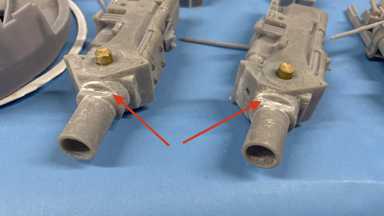
I then checked them with the kit's plastic bloomers and everything still worked including how the metal barrels engaged with the gun slide. Whew! Dodged that bullet. All of this mayhem is completely invisible in the finished model. 

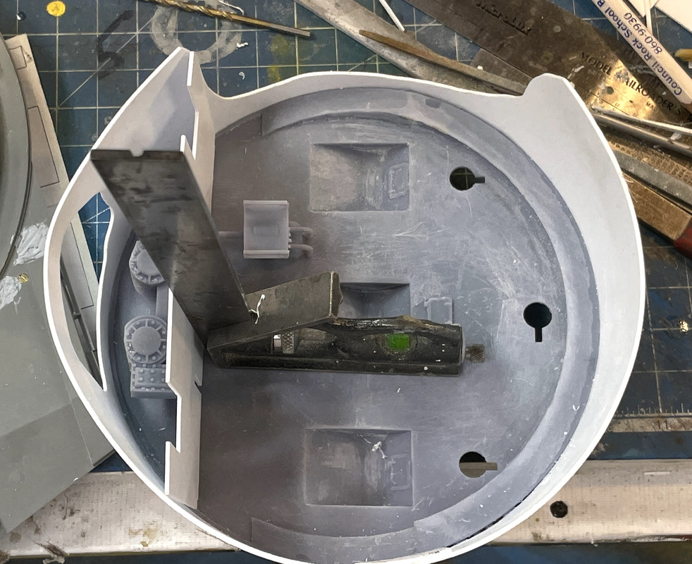
I then spent a lot of time fitting the gun rear compartments and the powder hoist operator's booths. The reason for all this fussing was the addition of the kit turret floor piece. I did not have that part as part of the design phase. It was just too hard for me to figure out what was what with it and I fully expected to do a lot of "field mods" to get it all to work. My expectations were correct.

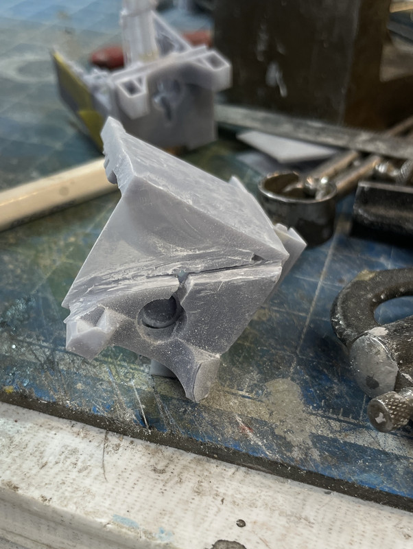
The first problem was relieving the bottoms of the compartment prints so they would drop down and back to the correct final position. This was a trial and error affair. I did the cutting with the Dremel Flexishaft and a diamond coated cutting wheel. This job creates a huge amount of UV resin dust and I wore my dust mask so I wouldn't kill myself.

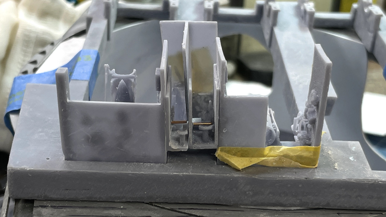
I also kind of knew from the start that my design of the powder hoist operators booths was going to cause a problem since in the rear ship, they share a common wall in the double hoist area as the powder trunks do. I produced them with two side was each. This is what it looked like when those two walls were trying to occupy the same space. Physics won't allow this.

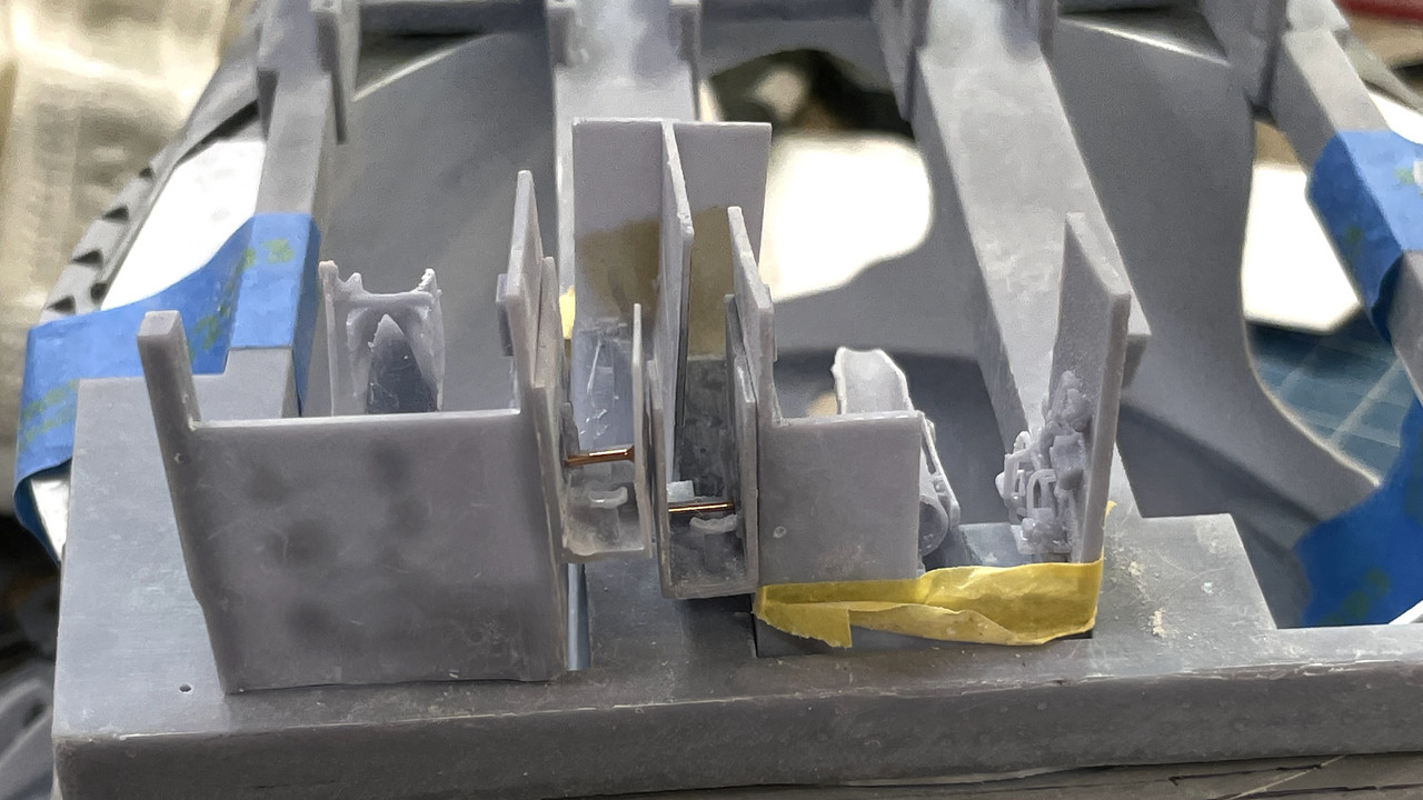
I had to surgically remove on of the walls. I also had to do major surgery on the edges that mated with the powder trunks themselves. Again, I new as I was drawing all this that I had absolutely no idea just how all these pieces were going to interact until I had the physical parts. After removing the wall, they do work together better. I CA's each respective hoist booth their gun compartments since the little observation window openings had to align for the booth to be at the proper height. I'm not worried about the open space beneath since the rear bulkhead butts up directly to these parts.

The other two guns powder carts will be down at the powder flat.

The right gun is going to have the powder door open with the cart in the upper position. It was especially trying to get the cart, the trunk and the rest of it to all work together. This is how it ended up. Again, the alcove part back wall with conceal that opening you see showing the cart's flank.

The last gun girder task was putting the thin styrene veneer on the rear compartment to act as the turret base plate. I made a paper template and then transferred this to the 0.020" styrene using the same PSA technique I used before. I will be using this technique a few times before the job is done.

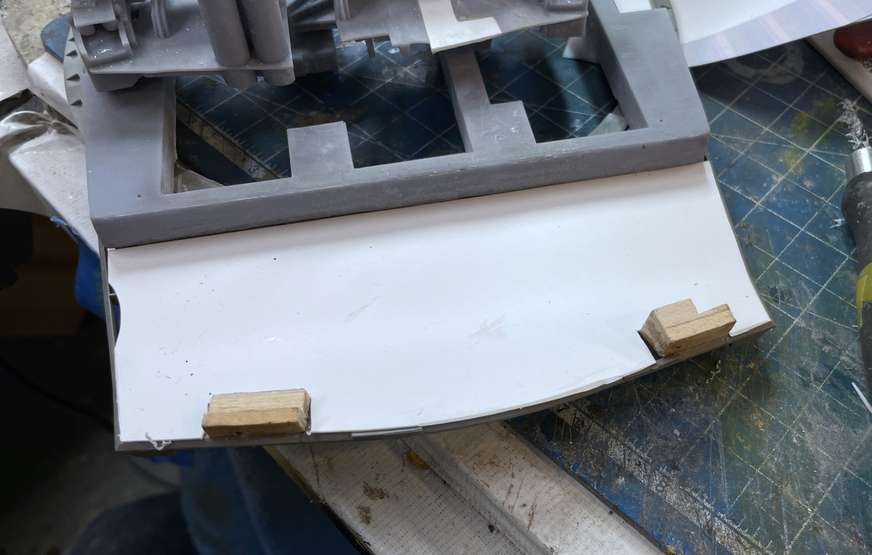
I test fit the rear compartment print to make sure that small lift the floor gave didn't cause any problems. it did not. This floor will have the non-slip flooring in the walkway like the prototype does.

I believe I can paint the gun girders now.

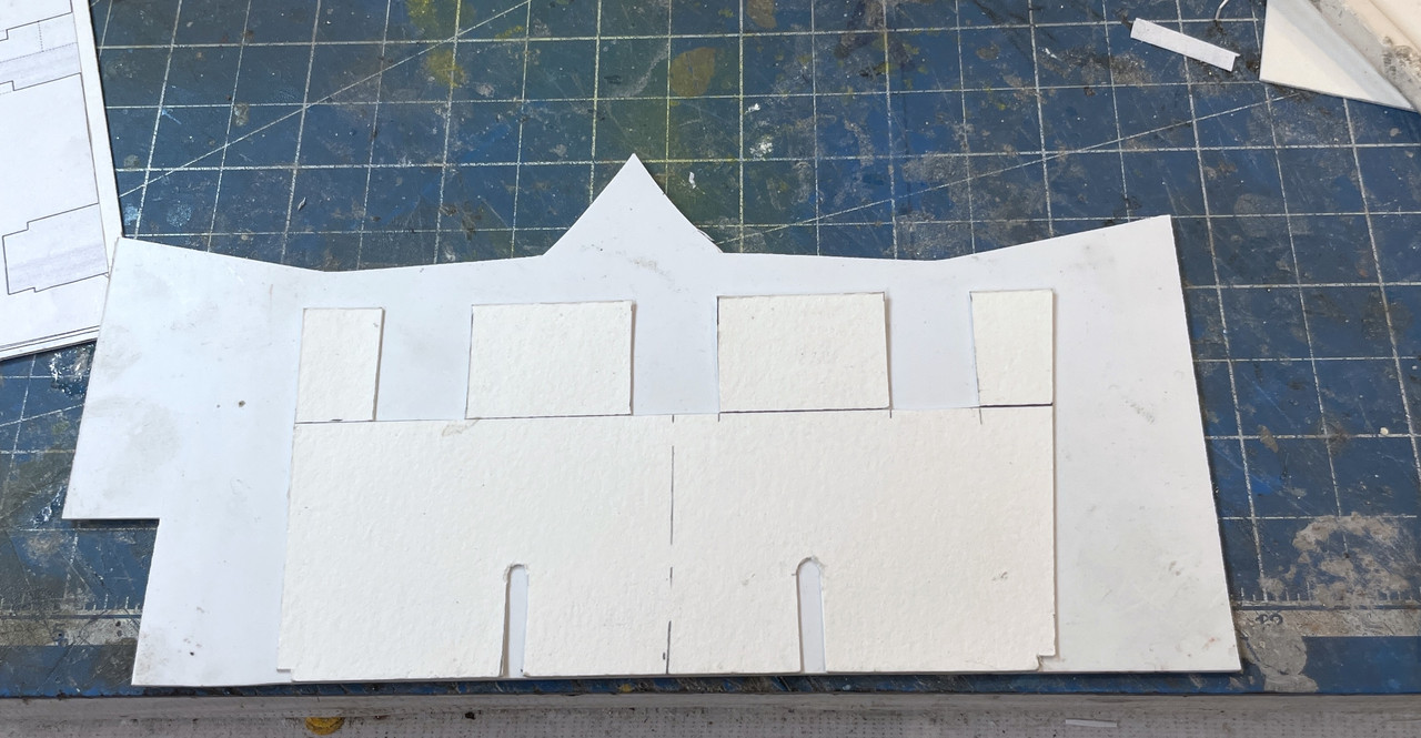
I got bacl to work on the pan deck. I had made a paper template of the transverse bulkhead that runs athwartship just behing the training machinery. I pasted the paper template onto a heavier strathmore stock and started doing the final fitting. I don't know why, but I found it necessary to make relief cuts in this bulkhead in SU. The guns were impacting it. I don't know the actual dimension of this bulkhead in the real ship. Since so many of my measurements are estimates I could have some stacking errors that crept in with the guns themselves. Just because they look great doesn't mean they're exactly scaled.

I added some height to my original drawing so it matched the height of the pan deck's walls. I then glued the strathmore template onto the 0.040" styrene.


I had to keep adjusting the width and positioning to get it just right. I went back and measured my full-size SU drawing to capture the distance from the front of the shell to the bulkhead and then divided by 72 to get the actual number. My positioning was very close. 

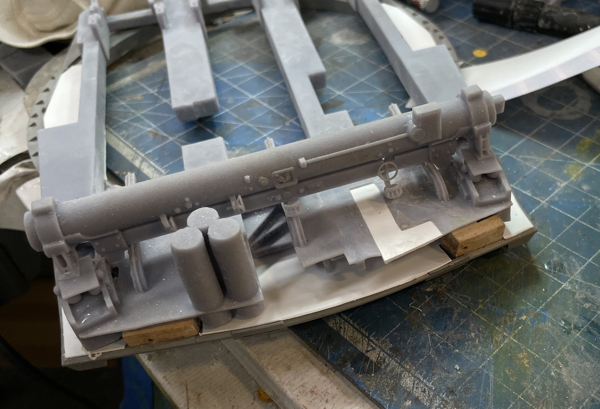
Another critical dimension was the positioning of the slots that the B-end hydraulics drive shaft that must align to the holes in the gear heads. It took a bit of fiddling to get this one right. 

I used a square to hold it in position while I started with solvent cement to tack it in place.

After the solvent cement set a bit, I went back and sealed all the edges with thick CA and accelerator. I will attach the B-ends AFTER all the pan deck is painted.

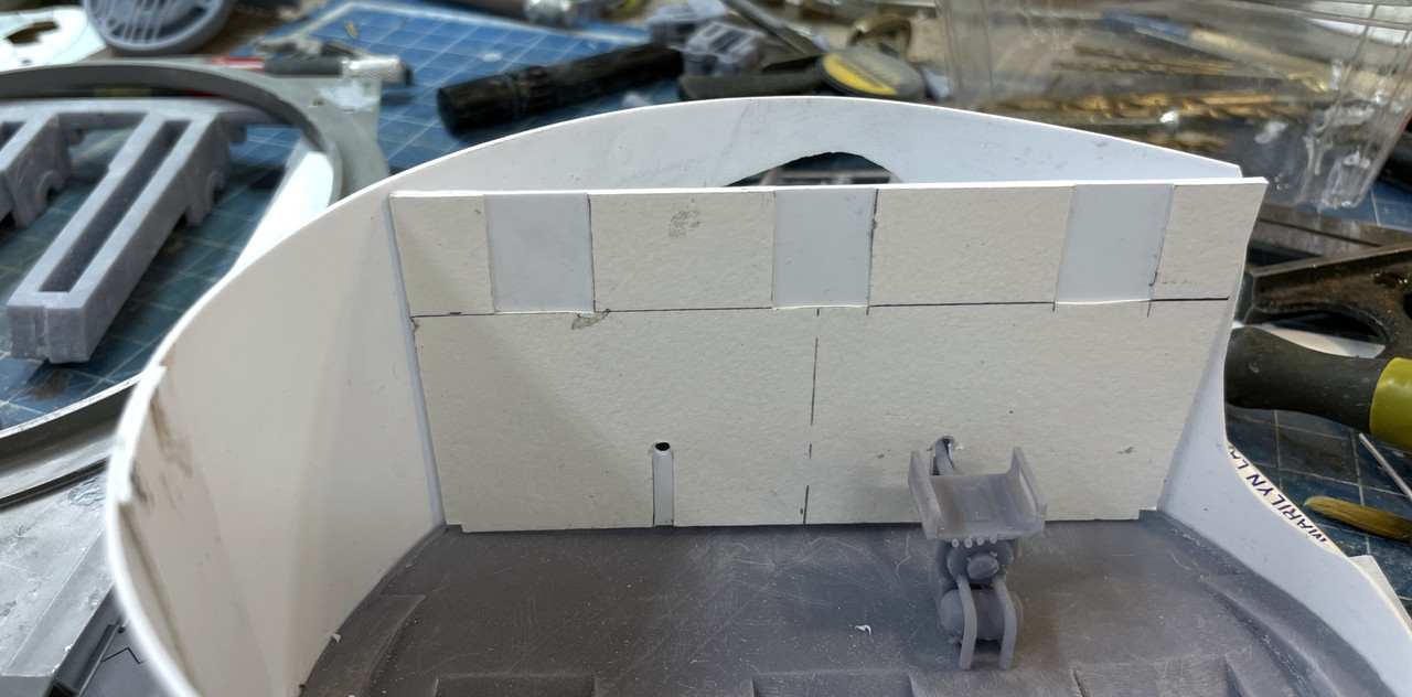
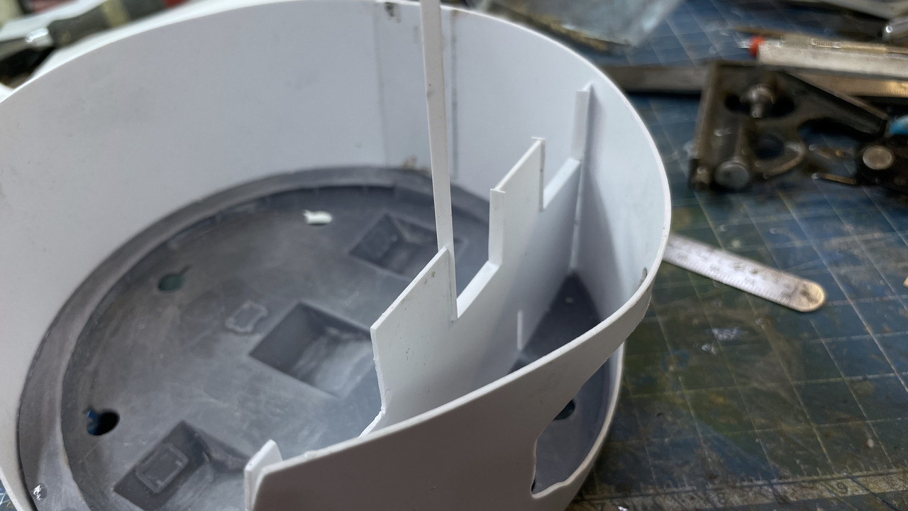
With the front bulkhead done, I crafted the center bulkhead that lies above and between the two gear heads. I had to notch this out just like the tranverse bulkhead to clear the gun, especially when they elevate and all the recoil mechanism on the bottom swings down. I'm only elevating the left gun, but the bulkheads have to look like the others could too.

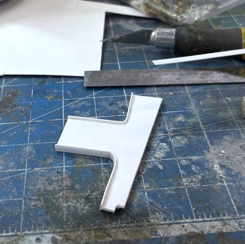
This piece also stabilizes the flimsy area in front as a result of all the cutaway work. Again, started with Strathmore, then transferred to styrene when it was right. This shows the Strathmore.

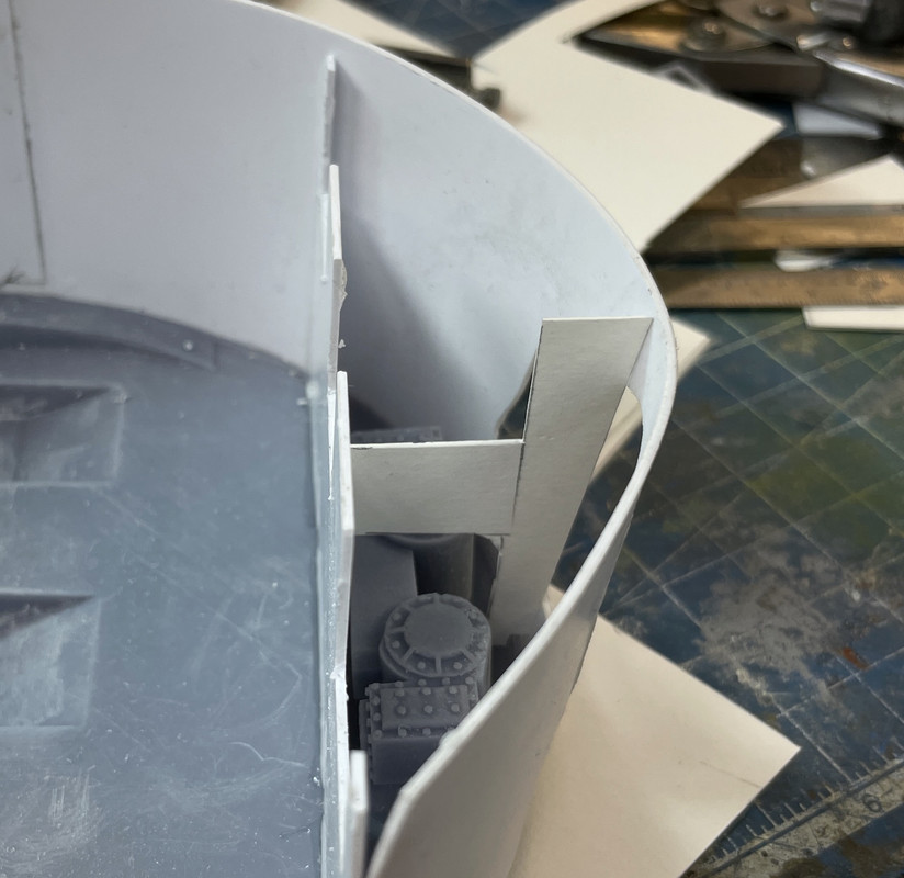
When the fit was right, I made the real one. In this case, I radiused both cut outs. I then added some 0.020" X .125" styrene strip to act as the typical welded webbing on all the perforations in all the bulkheads throughout the entire ship. This was fun, good old, old school scratch-building.

I did a final test fit, and liked it.

Now I had a decision to make. I couldn't glue this in if the training gear wasn't installed since I couldn't get the training gear in with this bulkhead in place. But I wanted the bulkheads to be all glued in before painting. I bit the bullet and prime painted the gear head, and installed it with thin CA. I then final glued the front bulkhead in place with solvent and CA as before. I then added some reinforcing blocks around that front butt joint. I didn't want it breaking loose. These are behind the wall and won't be visible through the cutaway. I'll just have do some fancy brush painting to do the gear head.

I put the webbing on the center buikhead so I had to put it on the transverse one. Finicky, but fun.

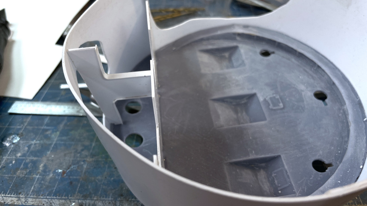
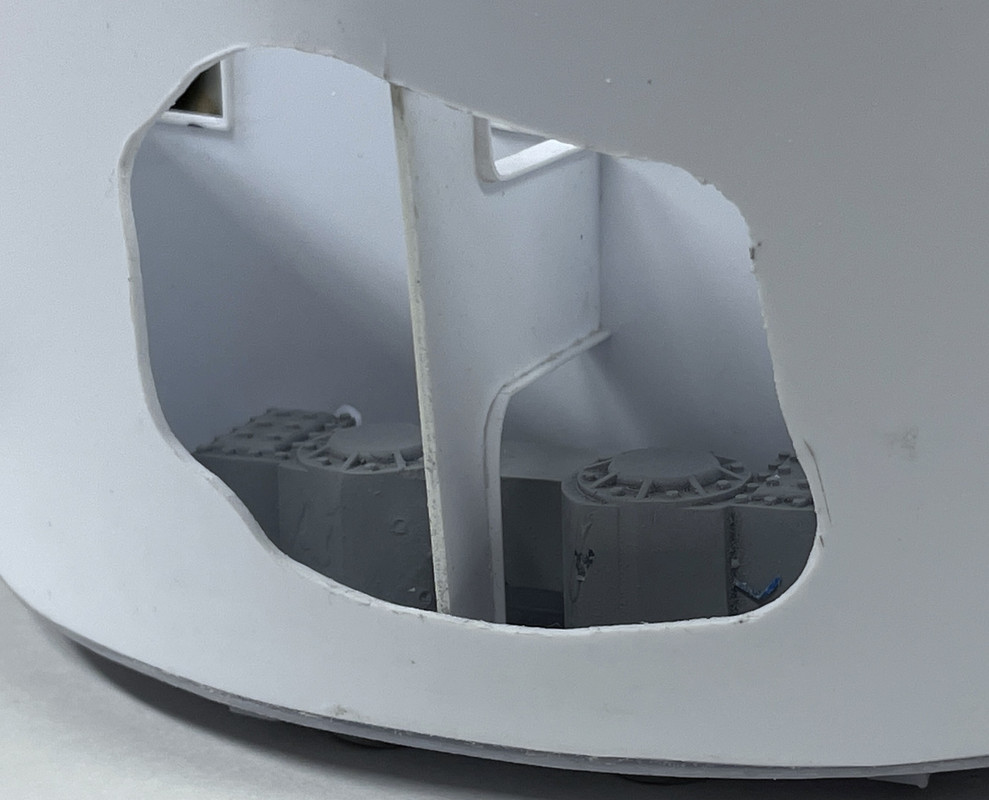
With everything glued in place, it's now ready for paint.

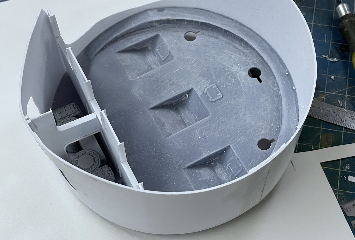
Here's the view through the cutaway.

I did one more print job.

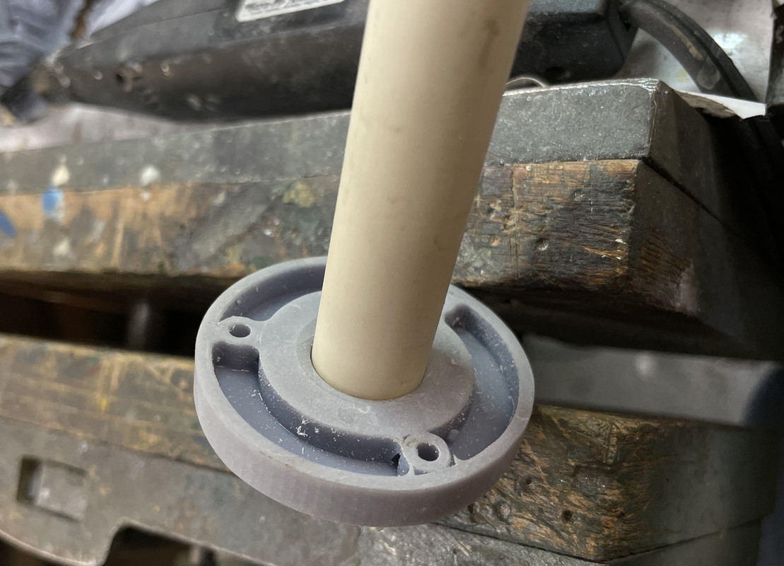
I was trying to figure out how to support the model on the display base. I was going to machine a part out of brass, but then said... "Draw it and print it". It's going to be below the base underneath in the circuitry box. The leads for the LEDs will come out of the hollow CPVC tube below the base. The screw holes are just place holders since I don't know what hardware I'll be actually using. 

The printed through hole is a couple of thousandths under 5/8" so the copper tube wouldn't get all the way through. i turned it into a ream by grinding a slice in the tube's edge and a cutting lip and by twisting it, let it open the hole up enough to pass it. It worked. And the plastic tube is a nice tight slip fit. This is the bottom that will be in the box.

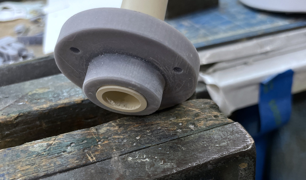
And this is the mounting surface that will go up against the base box surface. I notice a discontinuity on the one of the screw bosses. The radius didn't form a solid around that one. I hope it will work as it is.

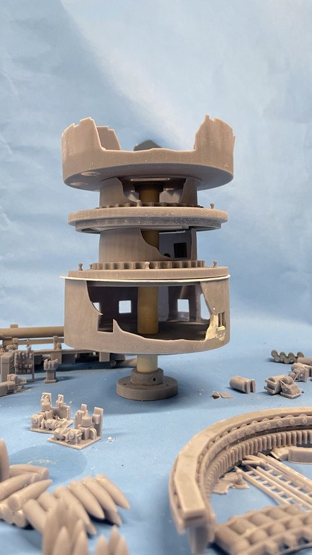
I did a quick estimate of the center column height and cut it off with my big chop saw. I put the stack together just for fun. It does not penetrate the electric deck. It sits in a socket, but as I'm writing this I realize that I will need to find a way to get all the wiring from the this deck, the pan deck and the gun house through that tube and down to the base. There's a lot of bulkheads that aren't going to have cutaways or be transparent so it shouldn't be a problem. Just have to keep it in mind. It's why doing all this journaling actually helps me produce a better model.

I don't actually know the wood thickness that my friend is going to use so the spacing below the powder flat is just an estimate. The actual boss diameter is .79" which is bigger than 3/4" and I don't know of a drill that size. I needed to give the walls some meat to support the tubing and the tube is 5/8". The boss is supporting the tube, not the base so the hole can be any size bigger that the boss.

Tomorrow I will tackle the electric deck. It too is going to have some scratch-built add-on small bulkheads. 

  • Member since
    March 2012
  • From: Louisville, KY
Posted by Builder 2010 on Thursday, September 1, 2022 6:49 PM

More work proceeds on the pan deck. Again using Strathmore art paper, I made three templates for the fore and aft partitiions. I then transferred to styrene, final shaped them and started to install. I'm not going to use transparent styrene. I have to use Med/thick CA to glue the styrene to the base UV resin and solvent cements have no effect on the UV resin. That means CA and it can cloud clear styrene. instead I'm just going to continue using the cutaways that were started with the outer shell.

I made another critical decision: I was originally going to apply the prototype's method of having the partitions go straight down from the turret ceiling to the pan deck. This would have meant inserting the entire girder from the top and still be able to glue it in place at the bottom of the pan deck. That was bad enough, But the partitions sit ON TOP of the trunnion caps, meaning the guns would have to be installed first. The guns completely block access to the pan deck! This simply wouldn't work.

Instead, I'm splitting the partitions with the lower pan-deck portion being measured and installed completely, then painted and have all the appratus installed. The gun house base structure gets painted, and all the apparatus installed. Then the guns go in with their trunnion caps and finally, the gun house partitions get glued to the flanks of the gun girders. I suspect that due to the spacing variations, the upper and lower pieces may not align perfectly, but they will be very hard to see and it's the only way I can envision getting it together.

This shows the split template. These were originally a single sheet. Notice how the partition is cut to go on top of the trunnion.

I make the template larger than needed and then creep up to the correct fit. It is critical that the pan deck apparatus fits between these partitions. The elevating gear goes in the same space as the gun pit and the training B-end goes in the in-between spaces. My gun pit spacing and even the gun girders themselve ARE NOT as accurate as I would llke and the spacing has some variability in it. But the appratus has to fit so I'm using them as the final positioning guide.

I made all three templates first. Two of these, the middle ones, will be in pairs. The outer one is on the back wall, but not in front since it would block the cutaway.

The port side partition needed some more fiddling to have it clear the reinforcing girder that encircles half of the pan deck base. This too was cut out and shaped while still using Strathmore. Paper is much cheaper than scrapping badly cut styrene.

This piece was then transferred to styrene, solvent glued to the other styrene and bonded to the base using accelerator and medium CA. After installation I wanted to add these side bulkheads. There appears to be lightening/access ports in them which I cut, first in paper and then in styrene. While they would have had webbing, the radius is too tight and the styrene would split under action of the solvent cement. So I left it off here. These could have been 3D printed, but I had no idea of how big they would be until building it. This is the paper template.

Here it is with the styrene.

Here's a view showing positioning of some of the apparatus with the next partition set in place. I haven't cut the cutaway on this so nothing is glued here. On my original plans I had another tranverse builkhead going across the back, but after careful review of the plan I realize that this dotted line was something that was below the deck. I also am not sure if there's a passage across the back from one pit to the other. I highly doubt it since this violates the whole philosophy of segregating anythng that could pass fire from one area to the other.

There would be one more side bulkhead spacer, in the fore part of that chamber, but it would be right in the cutaway. I may pit it in and cut it away too. That strange object that's on the bottom of this image is my lovely Browne and Sharpe small combination square viewed end-on. I use it during the gluing to help keep things plumb.

  • Member since
    March 2012
  • From: Louisville, KY
Posted by Builder 2010 on Friday, September 2, 2022 6:23 PM

Didn't have much time in the shop... was buying stuff for the Hawaii trip. That said, did get some more stuff done.

The pan deck partitioning is almost finished.

I was able to position all of them so the apparatus fit, but the variances I introduced in the gun girder land width definitely knocks the alignment off between the bottom and top partition halves. I was so concerned to get the gun spaces centered and correct width that I ignored the fact the the pieces in between the spaces were no longer equal. Forest and trees syndrome. Can't do anything about it. That ship has left the dry dock. It will almost impossible to visualize these erros in the finished model since the guns and the aft gun compartment parts hide almost all the happenings in the pan deck below. That's why the cutaway is so critical. Here's what's done so far. The apparatus is just there for spacing.

The relief cuts on the top of the middle two partitiions is for the piece of 0.040" styrene that I installed to give a positive stop to the middle gun compartment print. It protrudes into the pan deck space and the notches let the pan deck seat evenly all around.

I put on the gun house base and a gun to see what the view will be looking straight through. This is how viewers will see it. While it seems very light in there now... so why worry about LEDs, when all the stuff is on top it will get much darker and lighting will be necessary.

Painting all this will be fun...especially masking the walls so I can airbrush the deck surfaces. i thinking of outlining the cut edges of the cutaways with red or green to highlight them... thoughts?

The elevating box is the wrong hand for the right gun so the elevating screw is not engaged in it. Doesn't matter. it was just to get an idea of view.

Have a great, happy and safe Labor Day weekend!

  • Member since
    August 2007
  • From: back country of SO-CAL, at the birth place of Naval Aviation
Posted by DUSTER on Friday, September 2, 2022 10:05 PM

Nice looks like it gonna be alright. 

Oh, and 

Steve

Building the perfect model---just not quite yet  Confused

  • Member since
    March 2012
  • From: Louisville, KY
Posted by Builder 2010 on Monday, September 5, 2022 9:04 PM

Thanks for the kind wishes. Hawaii's gonna be great! Wish it wasn't so far away.

Even though it's Labor Day I did get some shop time. Finished up the Pan Deck partitions with the small cut down one in front. I cleaned up the edges a bit more and it's waiting for paint. LED wiring will come down behind one of the back bulkheads out of sight.

I started working on the electric deck and almost got it ready for paint too. I glued in that complex mid-section print with the training system and one of the projectile hoist power packs. I also had to do the cutaway on the this part's port side wall so you can see into it. I used the Dremel with a carbide router to make the cuts. Resin doesn't melt like styrene and works well with burrs and other high rpm cutters. Styrene melts so fast it just gums up the tools.

I did the fill-in bit like I did with the projectile flats to close the rectangular holes for the old design powder trunks. 

There are six, small bulkheads that fill the fore space where the training pinions are. They reinforce this critical bit of turret infrastructure. This took most of the afternoon. Each had to be hand measured and cut since there are some slight variations from side to side. What made it more challenging was the training pinions had to slip between nos. 2 & 3 and 4 & 5. When I first assembled them to look nice, they didn't fit and I had to start ripping them out. Since it's a styrene/UV Resin interface I had to use CA. This is good since the styrene has a so-so bond with the CA and I was able to rip stuff out (more than once), sand off the old CA and reglue until I got it right.

The Fit is quite tight. And then I had to put the pan deck on top with both pinions in their respective holes in the training gear heads, and then try and fit it together with the pinions not being cocked in one direction or another. This entailed more ripping out and refitting.

I finally got all six in and spaced so the pan deck worked. Then I had to go back and relieve all the slight misalignments with all these printed parts. I have reinforcing ribs under the pan deck with corresponding slots in the electric deck walls to accept them. I'm sure this is not prototypical, but I needed the ribs to reduce warpage of the big, flat pan deck base. They did the job, but they're a pain in the butt to get to fit into the electric deck slots. I almost got it done when it was quitting time. My daughter and son in law were coming over for burgers. They're now empty nesters with my youngest grandson starting as a freshman at Washington University of St. Louis in engineering and my oldest grandson entering his senior year at University of Illinois engineering.

Here's the completed bulkhead scheme. As you can see by the above image, you realy can't see any of it. What it did do was enable me to pull in the electric walls so they're true vertical. That large cut out area for the pinions left the wall unstable and it was warping out a bit. I put some filler pieces in the middle bulkheads to hold their spacing since it was so critical for the pinion fit.

Once I get all the inpingement areas cleared out and get the pan deck to drop flat onto the electric deck, I will be done with the electric deck and it too is ready for paint. All the other apparatus will go in AFTER paint. Actually, lighting goes in before paint on all the decks. I mask the tiny LEDs, but the paint hides the surface mount copper conductive tape. There will be a lot of non-viewable areas on this deck also which will make it easy to get the lighting wiring down to the central column with terminates under the electric deck.

Assembly progress is moving along pretty well and it may not take as long as I was anticipating to get it built. We'll see. There will always be more surprises. 

This is the illustration I'm going to include in the display along with the callout list. When I first developed the list I went into MUCH more detail, but realized it would bore people to death. Museum display designs usually have three levels of explanation. Level one is for the person who's breezing through and just looks at things that catch their eye. The model does that. Level two is broad head type that gives a quick view of what's what, and Level Three can actually get into paragrph text for those who want to stop and read. It was the level three depth that I'm still not sure about.

Here's the text to go with the callouts. Should it be more? Less? Just right? Feedback is requested.

  • Member since
    January 2015
Posted by TheMongoose on Monday, September 5, 2022 10:11 PM

Hey Builder! I've gone up and down the page looking at the text and then back up at the render. I think it reads pretty well. For me I don't know all the terminology but I was still able to figure out what was on each level and relate the text to the render. That should be a cool board next to the display!

In the pattern: Scale Shipyard's 1/48 Balao Class Sub! leaning out the list...NOT! Ha, added to it again - Viper MkVii, 1/32 THUD & F-15J plus a weekend madness build!

  • Member since
    March 2012
  • From: Louisville, KY
Posted by Builder 2010 on Wednesday, September 7, 2022 7:21 PM

Good Feedback. I have to get some big photo paper. I'm thinking to affix to the back Plexiglass so it's an integral part of the display rather than a separate piece that could get misplaced.

I seemed to have missed an entire post from yesterday's work. So I'm adding it here in front of today's post. Both were pretty intensive sessions with lots of stuff to show.

First of all I edited the turret drawing to display the main deck and what lies above and below it. It was a suggestion by one of my many readers. It quickly tells the viewer just how much of this machine is below their feet.

I made that correction suggested on the write up to spell out "Port and Starboard" and avoid acronyms.

I took two steps forward and two steps back yesterday. I finally got the pan deck and electric deck to mate. After chopping and cutting all kinds of places on the e-deck, and still having the rocking to and fro, like there was a high spot somewhere buried inside, I decided to do some lateral thinking and check the pan deck base. And of course it was bowed out. It was this prominent bow that was created the interference. I should have relized this earlier, since the inner surface was bellied and the partitions had gaps that I had to fill... a lot. I used a sanding drum on the Dremel and knocked down most of the bulge on the ribs and lo and behold, the two gets finally got it together!

Another view:

I'm really having deja vu here... I know I wrote all this stuff yesterday and have no idea why it doesn't appear on any of the four forums to which I post. I do all the basic text here since Fine Scale has the most cumbersome photo upload, having to first load to a service and then to this site. All the other forums you can just drag an image from my files and drop it in.

I wanted to get the pan deck ready for paint, but that required doing the electrical work first. I'm using surface mount warm white LEDs driven by CL2N3 LED driver chips. These little marvels cost about $0.25 a piece. You pump in anything direct current voltage from 5 to 90 and out pops 20 milliamps, just what LEDs love. No worry about current limiting resistors. You can string the LEDs in series limited only by the input voltage drops across each LED. Generally they drop about 3 VDC so you can run a 4-LED string with one CL2 on a 12VDC power source. I'm using a 12VDC LED power supply from Amazon that cost about $15. I'm using them all over the place on my model railroad and have another as my LED test rig.

The circuit consists of self-adhesive copper foil tape with the LEDs soldered into little 1mm gaps. I mark which end is positive (+) and negative (–), and ensure that I'm soldering them in correctly. The contact pads underneath the LED is tiny, and the + is much smaller than the –.  I run the circuit in a loop where I want the light to be and cut the notches. I use the continous corners that I was taught in installing burglar alarms in the late 1970s when we were using adhesive lead foil on windows to sense breakage. You bend the tape back on itself, then turn it 90 degrees to form a triangle and stick it to itself. I pre-tin both sides of the gap with enough solder to puddle a bit when I place the LED over the gap and heat the solder next to it. You don't heat the LED! They are temperature sensitve. I heat the foil next to it and let the solder, keep a little bit of pressure on the LED with a tweezers, and as soon as the solder melts and the LED drops into it, I take off the heat.

Here's the illuminated circuit. BTW: If you get the polarity reversed it doesn't damage the LED. They're diodes and simply block currect in the opposite directoion. These puppies are very bright and I may have to attenuated them by painting something on the lens. They are much brighter than they appear here. The wire is 30awg silicone insulated stranded. There's is very little current in this circuit and small wiring works perfectly.

And here's the e-deck lit. The translucency will be elimiated by the many coats of paint to follow. If it still shows up, I can back the panels with aluminum foil which totally blocks the light leakage. Half of this stuff will not be visible when the powder trunks go in.

Now to the ugly stuff.

I found that the boss on the bottom of the e-deck was completely off-center. The central hub was fine, but the surrounding circle was eccentric. I scribed a circle of what would be correct. I was going to attemp to repair it, but last night decided to print a corrected part which you will read about further down in today's post. Don't ask me how this could happen. I don't have a clue. Every (or nearly every) circle I draw in SU is concentric with others. It's very easy to do.

The other problem was the uneven wall height arround the pan deck perimeter. This had to be fixed. I used a surface gauge and scribed a line from the lowest wall point around the entire circumference. I then used an abrasive wheel in the Dremel and removed anything that was higher. It was a scary bit and could have wrecked the whole deal, but didn't. Today I trimmed all the rest of the stuff that was sticking up. I don't know what this amount of material removal is going to do with the final constuction. In actual practice the gun's recoil would possibly be too long for the ceiling height at full elevation. But I'm not elevating that high AND my guns can't fire and therefore can't recoil. And it may be a benefit. I may have made the elevating scews too short, but this extra 3/16" could be all I need to have them comfortably fit into the tilting boxes.

Today's post:

Still wrestling with the real world versus the 3D designed world. It's a shock when I find my brilliantly designed things don't quite translate into the solid objects of which this world is made. Case in point...

I decided to reprint the electric deck and the insert. There were aspects of both that could be improved and I had already drawn a later version of each. The big print worked overnight so it was waiting for me this morning. It wasn't bad although again it had large ribs in places that weren't on the design and again, I was able to surgically remove them without damaging what was there. The bottom of this new part did not have that off-center boss problem like the previous one did. In fact, it had no boss at all. Furthermore, to add to the fun, the center lug that sits on top of the central column, was not physically attached in the drawing and printed anywhere as a separate part. It was so well supported it just print right where it was, but fell off when I removed the support. I glued it back on with Gel CA.

I thought it was good that it didn't have a boss, but then found that when I assembled it with the projectile flat that lies below and added the projectile hoists, the electric deck was sitting about 0.080" above the projectile deck's inner drum held up by the projectile hoists. It NEEDED THE BOSS!

I made the boss out of a laminate of two pieces of 0.040" styrene, and attached it using 3M transfer adhesive tape. This stuff is contact cement that comes on a roll. I can be amazingly strong when applied to clean surfaces. The spacing is now corrected.

I spend more time on the projectile deck centers starting to get the powder hoists trunks final fit for installation. i also chose to install the other apparatus in these inner spaces. Visibility is terrible inside due to the vision blocks set up by the powder trunks. I suppose I could hack some material off of them to show what's behind, but I'm not inclined to do so.

I finished up leveling the wall tops of the pan deck and got it ready for paint by finish sanding and filling the outer surface. I double-checked the drawing and flat pattern created by the software to see if the errors were there. They were not! The entire length of the pattern was parallel. What I think happened were errors crept in during the bending and glue up. It's a conical shape and depending on how the final joining was made, it could have changed the height of the sides in places.

After sanding I went around and filled any gaps in the styrene-resin interface with Tamiya fine filler.

I took the pan deck outside and rattle-can sprayed it with Tamiya White Primer. 

And after using Molotow Liquid Mask, I did the bottom.

I put a final coat of filler on a few missed spots and will sand that in tomorrow's session.

I'm going to paint the wall gloss white, the floor will be linoleum brown, with the apparatus painted medium gray. Ladders and projectile hoist trunks will be white.

Next up was the E-deck reprint. This print, besides missing the bottom boss, had the front bulkheads printed in place and they looked good (except for the middle piece of the front wall and two of the arms breaking off during cleaning). There was just one small problem. The pinion gears and their housings couldn't go into the space. Once in the space they would possible work, but I couldn't get them in there. 

They fit in the drawing! That's becasuse, they aren't real and could move through the parts that were in the way into the space where they did fit.

It is essential that the pinions drop straight down into the space without a lot of wrangling. It's part of the entire pan deck structure and that's hard enough to get into place without having to hassle with the gears. So I took the router and removed the four inner bulkheads. I left the outer two in place. I will scratch-build them as I did with the last version, out of styrene spaced wide enough so the pinions fit

Re: the middle appratus print: The print was perfect except for a mal-formed wall and projectile hoist power unit that sits across one of the bulkhead openings. I will surgically remove the bad stuff and transplant a good from another print I have. NEVER EVER THROW AWAY REJECTS UNTIL YOU'RE ABSOLUTELY SURE YOU WON'T NEED THEM!

Tomorrow will be the last work session for over two weeks due to the Hawaii trip. I will still have access to the forums so I can respond to comments.


  • Member since
    March 2012
  • From: Louisville, KY
Posted by Builder 2010 on Thursday, September 8, 2022 5:59 PM

Last short work session before vacation (now.. really...when retired you don't "really" need a vacation. Everyday is a vacation). I finish sanded the outer walls of the pan deck and powder flat. Continued mounting stuff into the projectile flats, and reprinted successfully that complicated mid-section of the electric deck.

I woke up thinking that why should I spend the effort to cobble together a good part when I know exactly what failed in the print and know exactly why it failed. It took 10 minutes to add and modify the supports so that area wouldn't fail. I put it on the machine in the morning, did my exercises and by 3:30 p.m., the part was done.

These two images show the failure and the success.

It was actually the good kind of failure: nothing was separated from the part and stuck to the FEP.

After support removal and a couple spots needing some Bondic, this is what it looks like. It only took four iterations to get this one right. it was a complicated part that stretched the envelope of a single part print. 

When we return from the trip, I will grind off all the support scars. This version has the corrected pipe positioning to align with the training B-end one deck above.

And with that I see y'all in a couple of weeks.

  • Member since
    May 2009
  • From: Poland
Posted by Pawel on Friday, September 9, 2022 4:58 AM

Hello!

That piping looks really good!

You make 3D printing look really easy - thanks also for showing that there are potential for complications!

Enjoy your vacations!

Paweł

All comments and critique welcomed. Thanks for your honest opinions!

www.vietnam.net.pl

  • Member since
    March 2012
  • From: Louisville, KY
Posted by Builder 2010 on Monday, September 26, 2022 9:16 PM

Aloha! (that word and Moholo) is the extent of my Hawaian vocabularly after spending 12 days in paradise. It lived up to its expectataions and besides spending a small fortune, we really did Maui. We don't do serious hiking, paragliding, jetskiing or any of that 'rough' stuff, but we did do a lot of fabulous restaurants, visited a distillery, a winery, a glass factory, two botanical gardens, aquarium and walked on beach trails that gave views like this...

and this... This was outside our hotel balcony.

Maui was created over a million years by two volcanoes. Actully the five islands that make up Maui's neighborhood were all one island many years ago and between subsidence and errosion, the connecting land bridges submerged. It's why the channel between Maui, Lanai, Molokai, Kaho'alawe and the Molokini Crater is so shallow. The West Mountains are the remnants of a volcano that last erupted about 1,000,000 years ago, but the other, a 10,000 foot monster, Haleakala, erupted just 200 years ago, so it's only "mostly dead". The West Mountains, like the San Franscisco peaks at Flagstaff, AZ was once a huge mountain, but has broken down and erroded to a series of interesting peaks.

The best part of the trip was biting the bullet and renting cabanas during our four beach days. I am a true white man... I mean I am pitifully white, and sunburn just by imaging the sun in my head. Modern sun screen helps, but a cabana helped a whole lot more and made staying down by the sea for hours and hours much more relaxing. This was a view from our cabana watching the idiots going around in circles on jet skis and paying a fortune to do it. For the exhorbatent price of the cabana, they provided us with cold water and fresh fruit (including Maui Gold Pineapple).

We flew Louisville-Dallas-Maui-Dallas-Louisvile. The L'ville leg was on regional jets, but the Maui run was on an American 787-900. It was our first time on this plane and we flew Premium Economy. Premium Economy exceeded our expectations and seemed very much like business class (which I flew many time 20 years ago back and forth to Germany). I would recommend. It costs more than coach, but it's worth it. Five years ago, we flew First Class on a United 777 and it was definitely NOT worth it.

Now onto modeling. Finally got back in the shop and I hate to say it, but it felt great! I picked up where I left off; fitting the center section into the newly printed electric deck and getting the rest of it ready for paint. The was very little clean up on the middle part to make it work. I had to open up the hole for the projectile hoist trunk, and sand off some divots, but that was it.

I then spent time re-creating those little bulkheads on the forward part of the e-Deck. So little of these things is visible from the enclosed front that it's really not worth the effort, but you know... AWS. The pinions now fit this new space without binding. I also enlarged the semi-cicular pinion openings since the teeth were contacting the walls and weren't able to rotate. I want them to rotate so they can seat properly on the large ring gear.

The e-deck is now ready to receive all the apparatus either painted or un-painted... haven't decided yet. Assembly will continue more quickly now that everything's ready to go (except all those outer shells).


  • Member since
    August 2007
  • From: back country of SO-CAL, at the birth place of Naval Aviation
Posted by DUSTER on Tuesday, September 27, 2022 4:03 PM

Welcome Sign Welcome back! Yeah that is a magical place, even for us from Sothern California. Glad the work is progressing smoothly, guess the time  off was worth it- Cool

Steve

Building the perfect model---just not quite yet  Confused

  • Member since
    January 2021
Posted by JoeSMG on Wednesday, September 28, 2022 8:30 PM

Really impressive progress and I think you're heading into the hardest part of a complex assembly. I find my printed parts never quite fit perfectly; almost always everything is just a liiiiiitle too big...

Lots of shaving, sanding and handling = breaking, fixing and even reprinting!

You seem to be doing remarkably well though.

Hope you've smooth sailing and looking forward to the next instalment.


- Joe the SMG

  • Member since
    March 2012
  • From: Louisville, KY
Posted by Builder 2010 on Thursday, September 29, 2022 6:03 PM

Duster, lots of Maui had a very S. Cal look to it. Lots of brown coverings of the hills. There's a wet side and dry side and the dry side is very dry except during the rainy season. We were back and forth across the island a lot and almost put 600 miles on the rental. It's almost constantly raining in certain parts of the upslopes on Mt. Haleakela and the Western Mountains, while it's hot and dry in the low lands and the West/South sides of the island. Lots of strange microclimates just a few miles from each other.

Joe, you are absolutely correct. Just because you can make some fantastic shapes with resin printing, your model making work is far from over. Most of what you see on line regarding this tech are people printing figurines for fantasy gaming or whatever. Very rarely do they have interconnecting parts or have critical aspects to scale. When building something like this turret, fit as well as finish become in focus. Remarkably some aspects are quite close to design specs while other are not.

I do most of my creative thinking upon awakening in the morning and today was no exception. A couple of things got my attention. I had to remove part of the cutaway scrap from the gun house and reattach it since it's the part that supports the exterior periscope from the kit and my complex interior periscope that I created. Besides cutting it out and preparing it, I had to figure out where it would go. It's precise location was a bit hard to spacialize due to the missing plastic from the saw kerf. I stiffened the part with some more styrene and, after an initial fitting that was too far forward, I think I've got it right. It's not glued in yet, but it will be before the gun house is installed and painted. I wanted to preserve not only the periscope mounts, but also the little divots between them that denote the location of some hand grabs. The final position is actually rearward from this almost to that line of heavy rivets.

Work then continued on the electric deck. After laying in all the apparatus I realize that I DID have to make a cutaway of the powder trunk that's facing the viewer. You would completely miss the 300hp pump motor if the trunk was intact. Luckily, I decided to print all the powder trunks hollowed out. So when I cut the piece away using a scroll saw, I didn't have too much cleanup to do to open up the interior and thin the walls so they were more believable.

Using the same strategy, I realized that you wouldn't see anything inside the projectile flat cores either with the both the powder trunks AND the central column. I cut the trunk, but not sure what to do about the column. The wiring's going to run down that, just like the prototype. You can see some of it and it will be illuminated. I had to replace the trunk middle wall due to damage I created when using a carbide router to thin them.

And this is the very restricted view of the interior with the e-deck in place over it. This clearly shows why it needs to be lit. I just ordered more warm-white surface mount LEDs today from SuperBrightLEDs.Com.

  • Member since
    March 2018
  • From: Chicago suburbs
Posted by Luvspinball on Friday, September 30, 2022 1:30 PM

Fabulous work.  You are genius with the resin printer.

Just a possible "fix" to your center pipe issues.  Have you thought about a clear acrylic piece for the center column?  It would allow you to see the back wall of the decks and still allow the wiring to pass through.  If you are worried about the wiring showing, you could always slip in a significantly smaller "conduit" of styrene tubing to run the wires through.

Again, a masterpiece.

Bob

Bob Frysztak

Luvspinball

Current builds:  Revell 1/96 USS Constitution with extensive scratch building

JOIN OUR COMMUNITY!

Our community is FREE to join. To participate you must either login or register for an account.

SEARCH FORUMS
FREE NEWSLETTER
By signing up you may also receive reader surveys and occasional special offers. We do not sell, rent or trade our email lists. View our Privacy Policy.