I put in another 6 1/2 hours on Sunday, and the whole thing's almost done, I need to caulk the joints and attach the plexiglass lid and hinges, but that can be done at any time. I can start using it really soon! Hooray!
![Propeller [8-]](/emoticons/icon_smile_propeller.gif) Total Elapsed Time: 30 1/2 hours
Total Elapsed Time: 30 1/2 hours I apologize in advance for dropping into technical writing/ME report mode.
![Dead [xx(]](/emoticons/icon_smile_dead.gif)
From the start...
I started with a piece of 28 gauge sheet metal, and marked out the spray booth unfolded on it using a Sharpie.
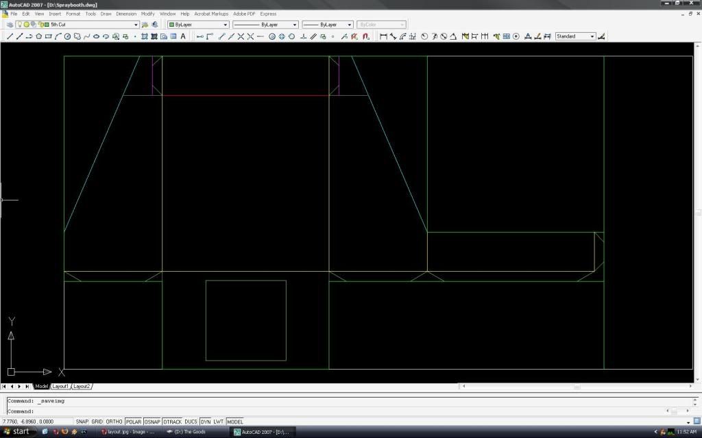
Next, the flattened shape was cut out using this attachment:

The shank of the attachment goes into any drill, and the internal gearbox converts rotary motion into a vertical snipping motion. I was a bit leery of using something like this as it seemed a bit hokey, but it goes through 28 gauge like a hot knife through butter.
A 3/8" drill bit was used to open up a hole to insert the shears to cut out the square in the bottom of the spray booth where the fan and reducer assembly would eventually go.
Lacking a brake, I had to get creative. I wanted stress bends on the back, as it was a large, flimsy expanse of metal with no real rigidity. My friend's garage has a cement floor with expansion joints about 1/4" wide. I laid the sheet metal over the expansion joint, and held a 4x4 with just the corner touching and smacked it with a hammer to imprint a stress bend in the metal. I rotated the sheet metal 180 degrees and repeated the work. This formed the familiar X shape ribs found on large ductwork, similar to what is shown below.

Using clamps and steel rulers to spread the force evenly, the tabs and sides of the spray booth were folded. Sharp 90 degree folds were made by holding a scrap piece of 4x4 on the inside of the fold, and hitting the outside of the fold with a hammer. After everything was folded, clamps were used to hold parts together, while 1/8" holes were drilled. The tabs were then riveted in place.
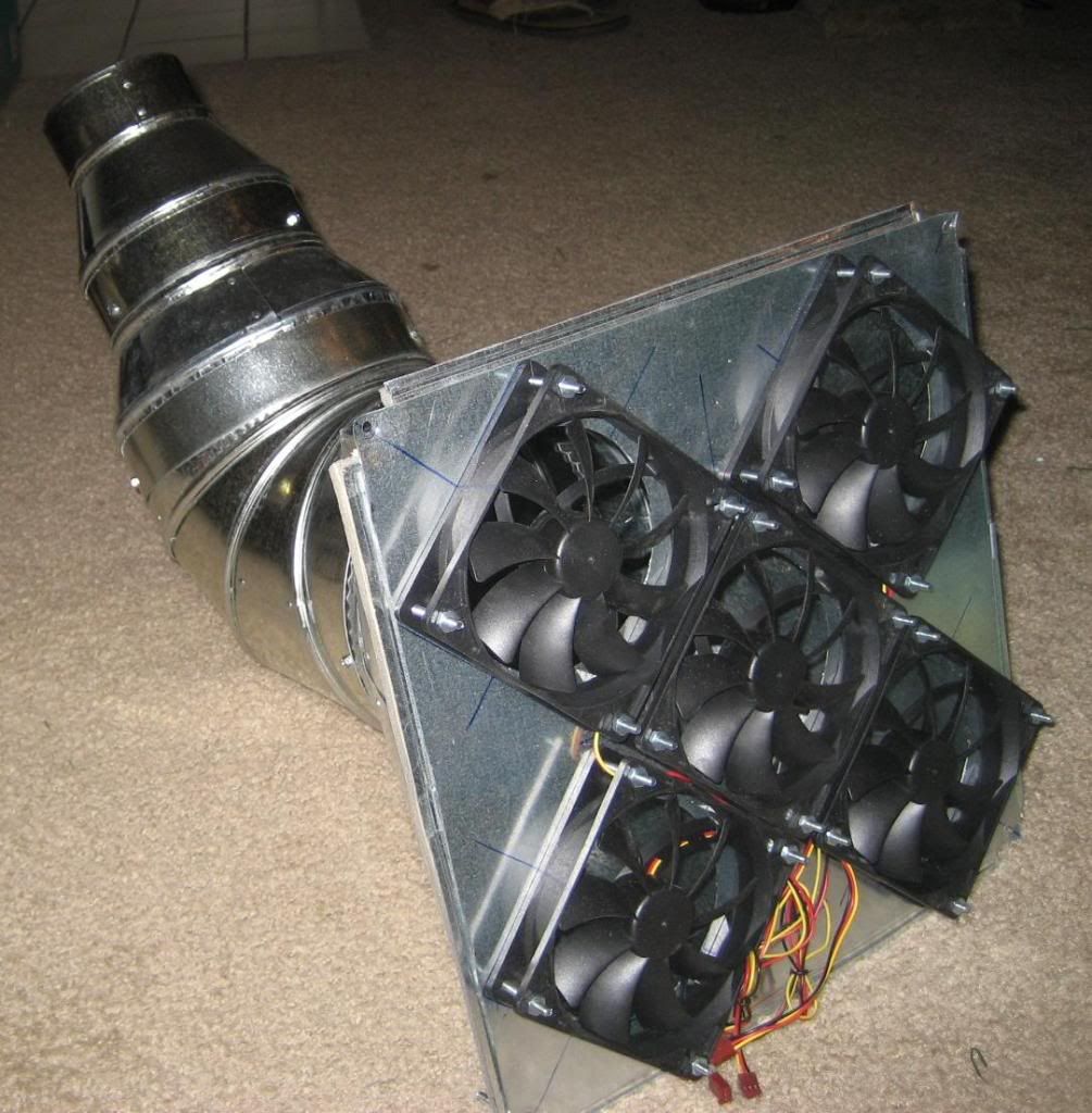
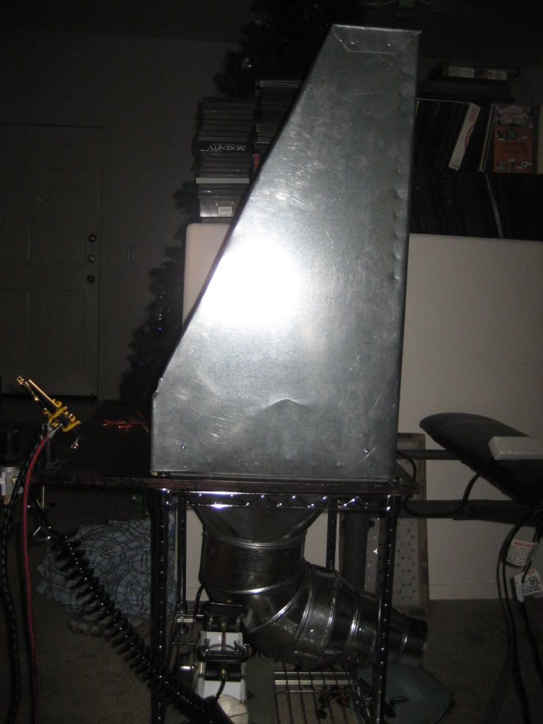
Next, the fan and reducer assembly was built. First, a leftover piece of sheet metal 12 3/4" on a side was cut out. Five 4 1/8" holes were marked out, and drilled out using a hole saw. The fans were then clamped in place and their mounting holes were drilled out as well. The fans were then mounted to the metal using machine screws in all holes except those along the outer edge. The square reducer's mounting flanges were pulled off, and slits were cut so that new mounting tabs that would sit flush could be bent out. The fan assembly was then clamped to the reducer flanges, and the outer fan mount holes were chased out through the reducer.
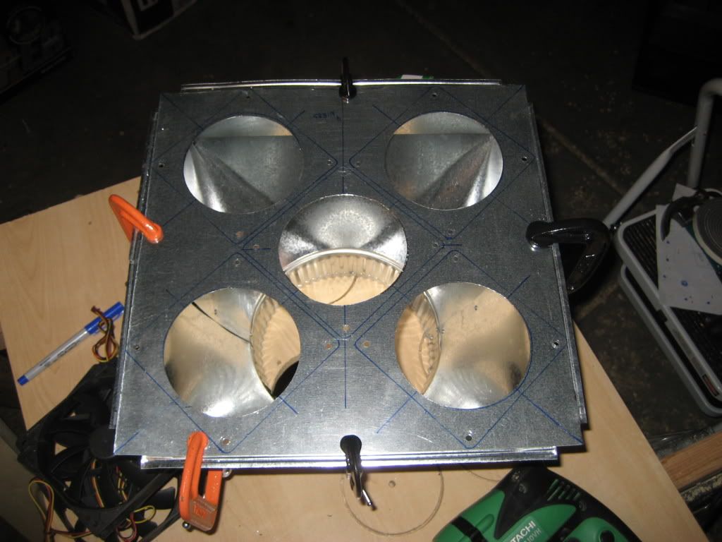
Next, the other reducers were were attached using self-tapping sheet metal screws. the joints were then wrapped in foil tape. Finally, weatherstripping was applied to the bottom of the reducer flange, the assembly was held in place, holes were drilled in the corners, and machine screws were used to mount the whole thing. The sheet metal work was now complete.
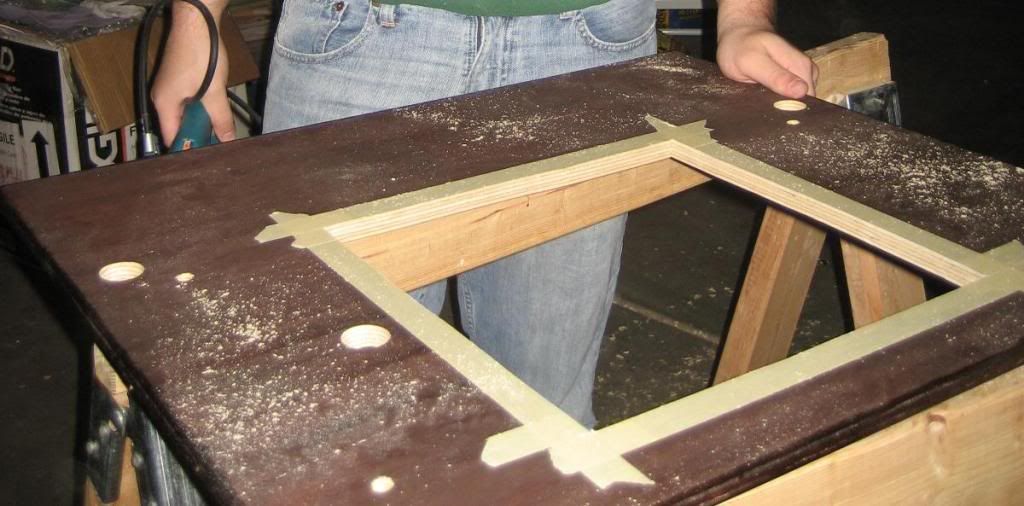
Next, the tabletop was cut to size, routed, and stained. Locations for the connecting bolts and the cart posts were then covered in masking tape to prevent splintering, marked out on the bottom, and drilled. A 3/8" drill bit was once again used to provide a starting hole for a jigsaw to cut out the square shapewhere the fan and reducer assembly would eventually go. A line of weatherstripping was laid out to form a tight seal between the bottom of the spray booth, the rivets, and the table top.
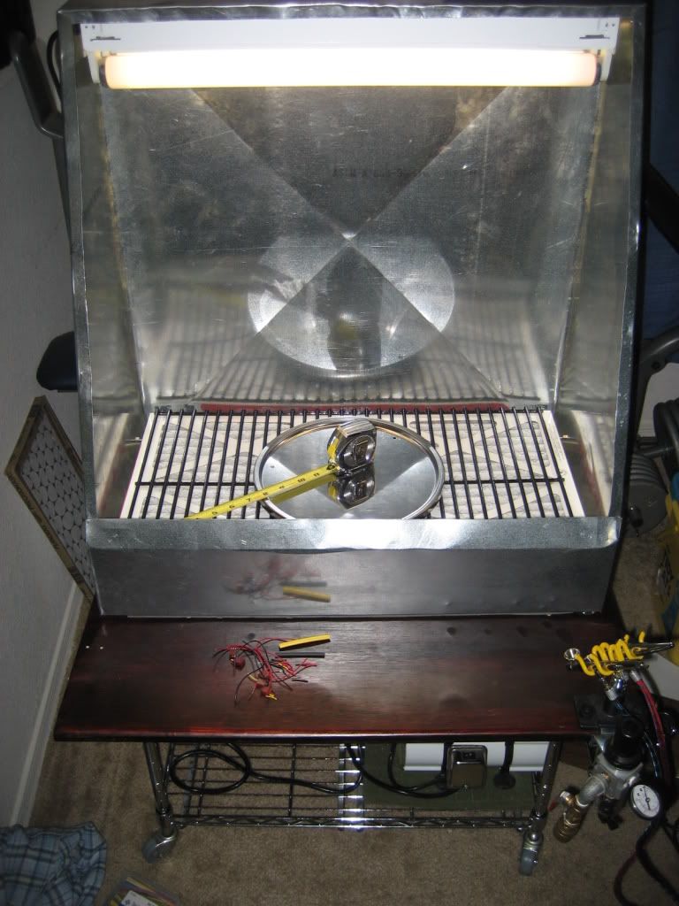
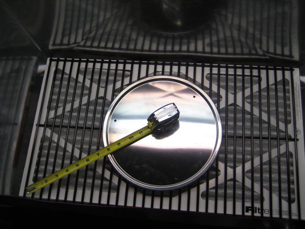
Major assembly was now done, and we started on odds and ends. With the tabletop complete, we clamped the spray booth in place, and chased out holes in the bottom of it for the connecting bolts, which were then bolted down, and the fan power wire. A grommet was inserted into the fan power wire hole. Holes were also drilled in the top of the spray booth to mount the fluorescent light, and it was then mounted. A hole was drilled in the side of the spray booth for the light power wire, and the light was then wired up. The aluminum spacers proved to be disappointing, so we used long machine screws as studs to rest the filter and grate on. The fan wires were attached in parallel, heat shrink-wrappped, sealed, and fed through the power wire hole. Next, they were wired into a quick disconnect, with the other side of the disconnect feeding into the power supply.
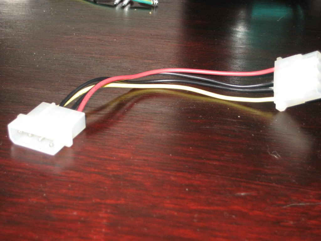
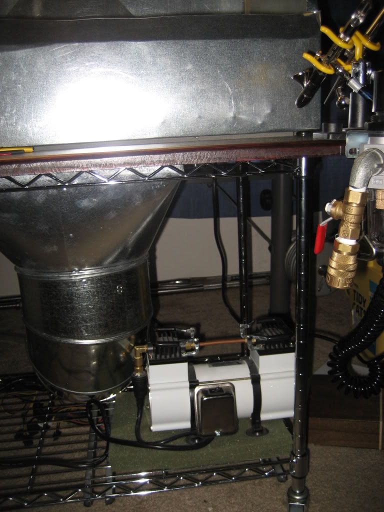
The whole assembly was then slid onto the cart poles, and large washers were used as spacers. Metal straps were screwed into the bottom of the tabletop, and thread through the cart sides to hold the assembly in place. My airbrush regulator, holder, and quick-disconnect were added to the front of the tabletop, while the compressor and power supply were mounted to the bottom of the cart. A power strip was mounted to the bottom of the tabletop, and the power supply, compressor, and lights were plugged in. The filter and grate were placed on their improved supports, and we called it a night!
Feel free to ask any questions you can think of...I'd love to hear your comments and friendly criticism too!
Cheers,
Alex