SEARCH FINESCALE.COM

Enter keywords or a search phrase below:

1:72 Iowa Class Mark-7, 16"-50cal Turret #1 with Custom Interior Start-to-Finish

30161 views
270 replies
1 rating 2 rating 3 rating 4 rating 5 rating
  • Member since
    March 2012
  • From: Louisville, KY
Posted by Builder 2010 on Saturday, October 1, 2022 1:56 PM

I'm okay with the center column. Clear acrylic tubing is hard to find and there are foot rungs that go onto it too. As you'll see in a few paragraphs, the cutaways give a reasonable view.

I started to add the lighting circuit on the underside of the e-deck before I could paint it. I got the foil tape and tinning done, but then couldn't find my LEDs. I did a pretty extensive search and the only thing that makes sense is I somehow threw them out when doing the cleanup prior to the trip. That'll teach me not to clean the shop!

I ordered 50 new ones and they'll be here early next week, and I only had a few of them left from the previous batch, so that's the silver lining.

Part of the circuit runs over Evergreen styrene. Styrene doesn't do so well when you're soldering over it. I tested this when doing the tinning and it was okay. I'll just have to get on and off with the heat quickly. That's not a bad thing since the surface mount LEDs are very heat sensitive too. The UV resin has a much higher temp profile and doesn't really melt. It's a thermoset not thermoplastic material.

With that work stopped, I got back to the projectile flats. I found that nice new one I printed last month was almost a 1/4" shorter than its mate. I think this error came from taking my height measure from a different reference point on the drawing. The structural steel framing on the two projectile decks is confusing. I decided to reprint this critical part. Here's the new versus the old one. 

The last one was redrawn with 96 sides on the circles, not 48 and this produces a much smoother curve... so smooth that I decided to reprint both projectile flats. I used this as an opportunity to fix some other issues that I had with this part. I also decided to draw the double powder trunk as a cutaway objects with nicely formed walls. Since I'm reprinting stuff, might as well do it all correctly. And on that theme, I'm also reprinting the deck rotation machinery that goes inside this structure. My original had the control link coming off way too low. The control is actually around head height on the outside of the inner shell. I also made it a better part all the way around. I'll reprint this today and it will all be ready for assembly on Monday. The upper level control needed some serious bracing if it was going to hold together as a little 3D printed part. Here's the new view showing the revised parts.

I'll just keep doing stuff over and over until I get it right. The only expense is resin.

  • Member since
    March 2012
  • From: Louisville, KY
Posted by Builder 2010 on Monday, October 3, 2022 5:59 PM

Happy Monday. All my reprinted parts are now done and almost all cleaned up. This week should be an excellent week to do the solvent painting outdoors. October is my favorite month!

The session was foreshortened today. I had an appointment in the a.m. with my urologist to decide to do anything with my PSA numbers that floating around in the 4s. We're going to take another measure in 3 months. At my age, 77, PSA numbers don't matter as much as do with the younger guy. And then this afternoon started some physical therapy to help relieve my annoying sciatica. Otherwise, I'm doing just fine.

All of the insides as well as the exterior shells of the two projectile flats are now renewed and correctly sized. Starting with the cutaway powder trunks. The difference between my feeble attempt to thin the walls of the previous, full-size trunks and my newly drawn and printed (as cutaways) trunks is painfully obvious. I still had sanding to do on the new printed parts.

Here is the reprinted inner ring turning machinery. In this print I set it up with the control rod facing the build plate and the gear head on the hanging end, therefore having no supports on this detailed portion. And it shows. The gear came out beautifully and meshes with the ring gear running around the deck circumference. It's interesting... even in this close coupled mechanism, the designers chose to have a motor attached to a hydraulic pump, piped to a hydraulic motor driving the gear box. It probably provides good control and protection against overloads.

Here's a top view of the newly printed projectile flat.

Here's the full stack showing both projectile flats. Their heights are now identical. Almost had a catastrophe, but it was averted. I thought I had cut through the majority of supports and went to rip the part off the remaining few. I miscounted. There were more supports on the thin circular wall than I realized and it fractured the wall like a spiral leg fracture, from the top edge one third the way around until it stopped at a thickened parts where one of the electrical boxes was attached. Again, with the help of Bondic, I reattached it, sanded off the excess after it cured and alls well again.

The cutaway powder trunk gives ample view into the space. The motor is hidden... I guess I could cutaway part of the central column...


  • Member since
    March 2012
  • From: Louisville, KY
Posted by Builder 2010 on Thursday, October 6, 2022 6:06 PM

Moving along... slowly. 

Yesterday I got the lighting completed for the ceilings of Projectile Deck 2 and the Powder flat. For the projectile flats I'm using 3 surface mount LEDs. The ceiling of the first p-flat was under the electric deck. The ceiling of the p-deck 2 is underneath the rotating ring of p-deck one, and the ceiling of the powder flat is the underneath p-deck two's rotating part.

I found out... and not sure why this happens... is that when you run a parallel circuit out of the CL2N3 LED driver chip, that one leg lights properly and the other burns out the LED. The reason I went to a parallel array because 4 in a series were very dim. I'm using a 12VDC power source and each LED drops 3.2 volts, so four in a series is 12.8 volts and exceeds the line voltage so they don't light fully. Three in a series works great. 

These two parts are the same diamter. The bottom looks smaller since it was further away from the lens. The wiring is captivated on the substrated by Bondic globs. They're led to the center column down which they will go to the circuit collectors under the base. Each individual circuit will have its own CL2N3 driver chip. On the bottom circuit you can see how I split out the copper foil to separate it from the rest of the series.

I used Molotow liquid mask to block out the LEDs in prep for painting like I did on the electric deck.

To prep the inner drums for painting, I glued some of the details in place that will be easy to paint after the base colors are in, but masked the floor locations for the other pieces so I can air brush the floor the linoleum color. I will also mask where the projectile hoists are going. This serves two purposes. It provides a raw surface for better glue adhesion, and it makes detail painting of the apparatus before assembly much easier.

I put down a patch of Tamiya tape, placed the parts and then traced them. Cut the tape to leave the patch in place.

After I got the two inner parts taped I glued them to their outer rings. As I was writing this, I realized that I really have to get the projectile hoist areas masked too before painting. If I hadn't stopped working this afternoon at my ascribed time (5:00p.m.) I would have primed that area without masking and that would have been a mistake.

I used urethane adhesive to hold these parts together. It's gives a little more working time.

Starting to do the same process on the electric deck. I located and glued in the double poweder trunk that passes through this space. I printed out a scaled image of the turret cross-section so I could get an approximate positioning. While they don't have to be exactly in line, I want them to be as close as I can get them. This chunk also stabilizes that thin printed wall. This serves as the perfect spacer for the separate middle piece since actually touches both walls.

I woke up Tuesday morning at around 6:00 and had a disturbing flash thought. The width measurements I gave my very dear and old friend Bryant (the fabulous bass player in my college band and a person I've known since 1963...and an amazing woodworker) for the inner width of the showcase was WRONG! He's crafting the base for me and I'm going to fab the acrylic case top. It was wrong because all my drawings of the turret and the resultant width measurements were WITHOUT the rangefinder ears that are so conspicuous in this piece of armament. I didn't draw them because this was a kit part that wasn't being 3D printed. The result, my 8" width measurement was a 1/4" too narrow and that would leave 0 clearance between the model and the case. He'd been routing the ogee edge and I hoped that he wasn't too far along. 

I was lucky. He's a day before it would have been very difficult and he's able to add and inch of width to the base which will give me a reasonable fit. Whew! It was weird. I just woke up realizing that something was off and it came to me that I didn't measure the ears. Subconscious thought it amazing sometimes.

  • Member since
    May 2009
  • From: Poland
Posted by Pawel on Friday, October 7, 2022 7:17 AM

Howdy!

Comin' along nicely!

Now connecting LEDs in parallel is something they warned us about, back when I was studying Electronics. Thing is, it's very hard to match those LEDs, and one of them will always "take" a little more current than the other - and then when it operates with more current, it gets warmer than the other, and with temperature it draws even more current - and so we get a so called thermal runaway. To prevent this each branch with LEDs should have a small resistor in series - that would cap the excess current and restore the balance. Looking at the datasheet of the CL2N3 I don't know why any LED should burn out... Maybe they just stopped working, because all the current went through the warmer LEDs?

In a situation like yours I probably wouldn't bother with a LED driver and just use resistors - much cheaper!

Good luck with your build and have a nice day

Paweł

All comments and critique welcomed. Thanks for your honest opinions!

www.vietnam.net.pl

  • Member since
    March 2012
  • From: Louisville, KY
Posted by Builder 2010 on Saturday, October 8, 2022 10:18 AM

Pawel, the runaway theory seems to hold up in this case. The single LED did start smoking a bit and that's usually a clue that's something's going dreadfully wrong. The LED drivers are $0.55 each so they're not really expensive (as compared to other things). I have a huge collection of various current dropping resistors left over from the days before I discovered the CL2s, that I can press into service as long as I can figure out the color bar codes on them.

Yesterday (Friday) was somewhat frustrating! The weather was good for painting and I really wanted to get everthing I could primed. I had to do some mods first. The projectile hoists didn't match the wall height of the projectile flat core. I had originally drawn these to match the shorter height, but I changed that last week when I found that the two decks were different heights. So I reprinted both of them to the higher wall height making the projectile hoists now too short.

So I used the surface gauge and laid out a cutting line to make the walls the same as the hoists. All good? Well... maybe not as good as it should be. Here's the new wall height.

And here's the stack showing the nice tight fit.

Then I found out why the two walls were different heights in the first place. Due to the large boss hanging down from the electric deck, the upper projectile flat wall height was shorter than the lower projectile's deck. In other words, I had forgotten that I had alredy accounted for this difference when printing them originally. The two walls were intentionally different. So now the lower deck's hoists fit perfectly as shown above, but the upper hoists are anout 1/8" too short. I really don't want to print another deck, nor do I want to mess with the drawing and print another set of three hoists. They were tough enough to get right the first time. I think I'm just going to scratch build some spacers to close the gap.

The next frustration kept occurring as I was adding pieces to the painting board. Some of the components, which I thought were fully done, were "almost fully done" and required some additional cleanup. One of the rear compartment prints had the spanning tray break off...AGAIN! This piece had a very thin weak spot as the tray joins into the cradle at the faux hinge. I've had to reinforce them with Bondic. It's that point that broke. I had to sand off the old Bondic and re-attach the piece. So this all took longer than I wanted. I was short on time. I had a physically therapy appointment at 4:00 to work on my sciatica.

I did finally get all the masking done of the projectile decks including the three spots on each where the hoists will be glued.

With that, all the big parts (except the rear bulkhead and the gun girder) are ready for primer. Masking the electric deck took a bit of time also.

Here are all the rest of the parts ready for paint. I masked the gun recoil slide area which remains as natural metal. I'm using the gun barrels as a convenient handle to paint the slide/yoke assm.

And the rest,

Besides the aforementioned gun slide, rear bulkhead, there are still a ton of even smaller parts that I'm not going to prime. Many will be painted when they're glued into their final locations.

The last frustration that kept me from painting was finding out that one of my LEDs illuminating the powder flat was sitting where the double powder trunk was going.

This is why!

And here's the fix. Re-rounting the copper foil tape to the rear. And as I'm looking at this image, I see that the other LED is also where the single trunk's going, so I have to move that too. Ugh! I don't know why soldering the LEDs over the styrene patch didn't clue me into the fact that the powder trunks went there. It just seemed like a good place to put the lights. Ran out of time before installing the LED. When I repair the tape, I no longer rely just on the tape's adhesive. I add solder to ensure a good electrical connection.

I have to keep reminding myself, "Scratchbuilding is fun! Scratch-building is fun!" Whenever I complain to my wife, she reminds me, "It's your hobby, no one is telling you to do it!" She is very unsympathetic.

Weather permitting, on Monday I'll have the LEDs re-routed, the spacers fitted on Projectile Flat #1 and get some primer put on. I'll also have the gun girder and back bulkhead ready for paint also.

  • Member since
    March 2012
  • From: Louisville, KY
Posted by Builder 2010 on Monday, October 10, 2022 8:33 PM

Happy Monday. The weather was PERFECT for outdoor painting. I took all the major and medium parts outside and used what was left of a can of Tamiya gray primer for the gun barrels, a full can of Tamiya white primer and then some Rust-oleum flat white for what was left after I ran out of the Tamiya white. I just plop all the parts on the boards to which they were stuck using rolled blue masking tape onto another big piece of cardboard and that onto the top of our two trash totes. There was just a slight breeze and I wore my full 3M chemical vapor mask since there was lots of spray around. I even took off my Apple Watch and put it in my pocket so it didn't get hit.

The big parts had their bottoms painted too. When the upper paint was dry enough to turn over, I sprayed all their bottoms. The LEDs were masked with the Molotow Liquid Mask.

The Rust-oleum needed 20 minutes to dry to the touch. I used the time to do the lighting scheme for the turret gun house. This time, instead of soldering over styrene, I made a laminate using some 1/64 aircraft ply. The wood will withstand the soldering temp much better than the styrene will. I use Eutectic Solder which has the lowest melting point of tin/lead solders. It has the same freezing and melting point with no transition zone. It is 63% tin and 37% lead and melts at 183°C (361°F). Having instant-solid transition eliminates the opportunity for a "cold" solder joint. Cold joints occur with other solder blends when the joint is moved during the time when it is slushy (neither liquid or solid). The crystaline structure that forms is non-conductive and ruins electrical conductivity. It's slightly more expensive, but it's worth it.

Again, I used Bondic to make instant wire clamps. I again used the 3M transfer tape to hold the front and back light assemblies into the plastic shell. This will all be painted white like the other walls.

I'm thinking about scratch-building the last bit of wall detail that goes on the back wall of the gun house. These are basically a bunch of wiring and junction boxes.

So here are all the pieces back in the drying solid before the detail painting begins. 

As an aside, the exercise program I'm working on along with the TENS 7000 that I bought from Amazon appears to be working. It's making the sciatica much better. The TENS unit stands for Trans Epidermal Neural Stimulation and uses high frequency electrical waves to quiet the nerves down that are generating most of the pain signals.

Tomorrow, I will begin some detail painting. I also have to bite the bullet and start working on the final pieces of the puzzle: the outer barbette and outer shells of the lower decks.

  • Member since
    March 2012
  • From: Louisville, KY
Posted by Builder 2010 on Tuesday, October 11, 2022 7:39 PM

You're right Steve, many folks (including me) use wire to replicate tubing and piping. I often do this using both phos-bronze 0.020 and 0.032" wire, High E guitar string (approx. 0.010" and .5mm solder wire for pipes that bend a lot. I wanted to push the envelope here to see just what could be reproduced on the printer. I was happily surprised just how much could be done with the printer.

I will be using old school methods to put the last bit of detailing on the gun house back wall. On the upside, it was really easy to run the piping in SketchUp knowing just how well it would fit and not having to drill tiny holes at weird angles in the parts. I will be doing that to put the foot rungs into the sides of the gun girders (and I'm not looking forward to it).

Very short session today, and I woke up thinking about how to make the outer cylinders and the barbette. I decided to hold off in detail painting until I get further along with these outer barrels. Reason? There are some critical fits to the inner structures and the round outer decking that must bridge the gaps between the inner and our barrels. I don't want fancy paint and detail parts in the way as I massage all this stuff to fit. And massage i definitely will have to do if past experience is a prolog to future experience.

I already printed out the patterns for these cylindrical shapes. This one is the biggest. It is the outer shell for both the powder flat and the lowest projectile flat. It is also cut on a bias at the bottom where the entire stucture is welded into the ship's framing. Only on turret #1 is this angle cut made as the ship is already narrowing at this point. There are no powder magazines flanking #1 turret because of this narrowness. The other two turrets have some room between the turret cylinders and the ship's armor belts.

Here's Jim Slade's rendition of this barrel (straight and tapered portions) that he created from the actual ship's drawings. The fingered extensions at the cut off portion are the weld points to tie the turret into the ship's structure. Notice that this is where the roller bearing and gear rack gets mounted. I hope to be able to do mine this way also. Ttuhat hatchway is the only opening into the turret other than the entrance under the rear of the gun house.

As before, I stick the pattern onto the 0.040" styrene with the MicroMark Pressure Sensitive Adhesive, just lightly applied to the edges. I then scribe with a #11 blade and then snap it aprart.

Here's all the parts for this barrel. The circle will serve two functions. It will be the former to mold the sheet into a drum, and it will provide the stock for the annular decking that is around all three lower decks: powder flat and the two projectile flats. 

The odd shaped pieces will be the angled flats that get glued in after the cylinder is formed. 

My challenge is three fold. I have to get that stiff 0.040" styrene into a cylinder with the ends matched and glued so it won't pull apart. I aslo have to glue in the annular decks which will reinforce the cylinders, and lastly, I have cut the entire cylinder assemblies in half since I'm planning on doing it as a clamshell.

That splitting into clamshells is a huge question mark for me. It has some unique value in showing what's going on in that annular ring, e.g., the air bottles and the powder scuttles. But it will be very challenging to get the cuts done AND STILL have the halves maintain their cylindrical profile. I'm rethinking this idea and will maybe revert to cutting away some of the cylinders in strategic locations while still preserving their structural integrity.

First things first. I've got to form the cylinders and glue them in such a way to keep them together before any cutting.

  • Member since
    March 2012
  • From: Louisville, KY
Posted by Builder 2010 on Wednesday, October 12, 2022 5:37 PM

Got some suggestions for making that flat styrene round; using a rolling pin or heating in the oven. I was not going to attempt the oven. I've had bad experiences with heating styrene to bend it. It quickly goes from soft to a mess. I did try using a rolling pin over a soft substrate. Did not create any curvature at all. Ended up doing it the hard way.

First I needed to stabilize the various rings so I could get a test fit on the wrapper. I have a pile of 3/8" threaded rod left over from the Sikorsky S-38 restoration. I cut another annular ring and put them together on the threaded rod with some big fender washers. I immediately ran into dificulty with the 0.040" disc thickness. It was flexing all over the place and made wrapping thes sheet very difficult.

Regardless, I was able to test the wrapper fit and it was the right length. I actually figured out the disc diameter by dividing the wrapper length by Pi. That number still works! Using tape and rubber bands I got it to stabilize long enough to take a picture.

I added a splice plate on the squared ends of the wrap and glued it old school... I mean really old school using Testor's tube cement. I find this standby adhesive works well when you're gluing large surface areas. Liquid cements seem to evaporate too fast to get a good adhesion. Clamps insured that the joint stayed together during curing.

Because of the thinner sections where the cutouts are, the cylinder wants to turn into an oblate spheroid (football) shape, but the rings will force it to round out eventually.

While this was curing I got to work on the annual discs opening up the inside to create the actual ring shape. To establish the i.d., I first tried to trace the o.d. of the powder flat's lower edge, but the accuracy of this method was dubious. The ring needs to fit quite tightly.

Next attempt, I used the caliper to measure the diamter, split it in half and used a dividers to scribe an accurate circle. This worked well and after a tiny bit of shaving with a #11 blade, got an almost perfect fit. It was originally too tight and caused the thing ring to fold over.

After taking off the clamps and trying on the drum, I found that the 0.040" styrene ring didn't have the structural integrity to withstand the drum's springiness and it was distorting all over the place. Ergo, I can't use this thin stock for the annular rings. I'm transitioning to 1/8" Masonite which is much, much stiffer. The extra thickness shouldn't detract from the model. It will also provide enough lateral strength to retain the drum's shape when (or if) I decide to split the hemispheres for the clamshells.

I was originally going to use this piece of Masonite scrap, but I found some better pieces floating around the shop. The lowest ring has the cutouts and this piece will work for that one. Waste not want not...  The only trouble with Masonite is the porosity of the cut edges. I have acrylic sanding sealer that, when applied in several coats, gives the edges a finished look.

Tomorrow's a physical therapy day again which will cut into work time.

  • Member since
    March 2012
  • From: Louisville, KY
Posted by Builder 2010 on Thursday, October 13, 2022 8:55 PM

PLAN A: 0.040" thick annular ring. Failed due to too much flexibility

PLAN B: Cut annular rings out of 1/8" Masonite... nice and stiff, but a pain to cut and finish

PLAN C: Idea given by Dioramartin on Kit Forums to make the thin rings strong by using Evergreen structural shapes. Three times a charm. I have made many scratch-built items using Evergreen structural shapes and I should have thought of it. But... who cares. You take good ideas from where they come.

Using 1/4" Evergreen I-beam stock I cut a series of peices to stiffen the annular ring and then glued another ring on top of this making a completely stiff assembly.

I used a piece I was going to scrap for the bottom web leaving the perfectly fitting one as the top visible ring. 

This was pretty cool since the 1/4" thickness put the ring's top level almost in perfect line with the floor level of the powder flat interior. Happy coincidence.

But there's a wrinkle! Two parts of the this ring have to be chopped off due to the truncated aspect of the #1 turret's lower end. This cut removes a significant part of the ring's inner structure and destroys some of its structural integrity.

To resolve this dilemma I added some more interal structure. This helped a bit.

After making the cut, you can see there's not much left of the old lateral I-beam.

An added web of 0.040" styrene restored some of the strength. I still had shape the web a bit to get it conform to the rings circumference.

The true test of all this work was putting the skin on it and seeing if it held shape. It did what it's supposed to do. When the other rings are in place the oblate shape will round out nicely.

Here's a side view of this assembly.

And here was a test with the truncated wall. Clearly, it will take a bit of finessing these flat walls to get them tight, but I have no doubt that it will look okay.

Getting this drum formed and solving the annular ring problem was huge for me. I really was concerned about this aspect of the build. I have to make two more ring sets for each projectile flat, but having a viable method takes all the angst away. I've left the settings on my two Starrett machinists dividers from the final ring i.d and o.d sizing so I'm certain that the additional rings will be exactly the same size, therefore guaranteeing that the drum will be perfectly cylindrical from top to bottom.

I also realized today that I did NOT make templates for the barbette portion of the outer drums. That and the extra material being consumed in making the additional annular rings created a stock shortage. I put an order for two more 12" X 24" sheets of 0.040" Evergreen Styrene. I ordered it from my wonderful local hobby shop, Scale Reproductions, Inc., even though he doesn't stock these larger sheets. I have a goal in flife to keep them in business. The model building community in Louisville, KY is alive and well.

Due to the strength and stability of the constructed rings, I feel more confident that I could go with the clamshell scheme.

  • Member since
    August 2007
  • From: back country of SO-CAL, at the birth place of Naval Aviation
Posted by DUSTER on Thursday, October 13, 2022 9:21 PM

Yep!  I got the same answer.

This is gonna be a hum-dinger when your done, for sure.

Steve

Building the perfect model---just not quite yet  Confused

  • Member since
    March 2012
  • From: Louisville, KY
Posted by Builder 2010 on Friday, October 14, 2022 9:21 PM

I sure hope so... I definitely putting in the effort.

Worked on the second set of annular rings today, with a break to go to the hobby shop to pick up more 0.040" large sheet styrene. When he special ordered the large sheets for me months ago, he ordered more than I needed. He still had it and I bought more.

I measured the rings for the projectile flat, cut it all out and found that my i.d. was about 1/32" too big and wouldn't work. That's part of the reason why I was running out of my original stock. I remeasured and re-scribed. For the first of the two rings, I scribed the circumferences and then made radial scribes to faciliate snapping off the scrap.

While this works okay, it's a bit tedious and also leaves some inconsistencies that need to be sanded out. On the second ring, I realized that if I scribed the circles just a bit deeper, I coud snap the scrap out directly, leaving a much smoother and rounder edge. It also took 1/3 the time.

I also was being really anal and actually laid out the 1/6 spacing for the internal bracing. An absolutely meaningless exercise that will never, ever be seen by anyone. But it was fun.

To glue on the top piece I used some angle blocks to hold the edge in line. Liquid cement all the way.

I test fit the stack to see how it all aligned.

And then I fit the upper and lower annular rings into the drum and was rewarded with a nice rounded drum. I was almost tempted to glue it at this point, but it was very near quitting time and I didn't want to do anything rash. I've said it before, "I am not patient! I am persistent!" It's that persistence that has me doing stuff two or three times until I perfect the method, but I will screw up when I don't allow time for glue or paint to dry.

I've created the development drawings of the barbette pieces. I don't have a working CorelDraw any longer, and am not in a position at the moment to buy a piece of $400 software. I have Inkscape and MyDraw. Both are decent, but neither works for me to make full size templates on US Standard Letter Pages. 

Coreldraw is simply the best vector drawing program I've tried. It does several things that really help. First, it enables you to move the ruler origin anywhere on the drawing page. It makes it so much easier to establish accurate guidelines when you can set zero at the edge of the object. It also enables you to tile prints that exceed the size of your printer's page. I can't figure how to do this in MyDraw at all, and in Inkscape you have to export pieces of the drawing as separate PDF files, which is a total pain in the butt!

I ended up printing a page scale image of the three templates with their 1:1 dimensions. Two of them are fully rectangular and will be easy to layout on the styrene. The other has a simple curve on top and bottom edges and I will work that out somehow. Corel also enables scaling very easily. I also have skill with Adobe Illustrator and found it too to be clunky and difficult to use.

  • Member since
    March 2012
  • From: Louisville, KY
Posted by Builder 2010 on Monday, October 17, 2022 5:58 PM

In order to ensure that I can butt glue the tapered portion of the lower shell to the previously-built straight portion. I needed to have an adapter that combined the straight and angled portion which could provide more gluing surface. Enter the 3D printer. I drew a curved adapter on SketchUp matching the included angle. It printed in 1 hour and 15 minutes and was just what was needed.

I cut out the tapered portion from the newly acquired styrene sheet using the glued-on-pattern method I used before. I glued the joint plate on one side, but did not glue the cone together. I waited to do this until the cone was almost entirely attached to the straight section, thereby taking up the slack as I went along and adjusting as I went.

I used Gel CA to hold the adapters around the perimeter. The annular rings ARE NOT glued in, but later some thin CA did get down then causing a minor panic, since there's a lot of stuff to do before I permanently glue them in. I got it loose quickly.

I could really use some longer clamps to get down the wall's height a little better, but I made due.

Gluing started out at the back center and worked around both ways towards the joint section. I glued the piece to the adapters using thin and med CA while trying to keep the long junction as close in contact as possible. I glued that line with solvent cement. There will be filling and filing to do, but that's to be expected with pieces of this size and nature.

As with the other pattern-taken-from-SU-Unwrp and Flatten parts that I cut, there was a length discrepency here as well. In this case the flat part was short. To close this gap I'm filling it with some thing strips to better conform to a curve that would be difficult with such a narrow single piece. I can do wonders with filler and it will be fine. Besides, this is at the back of the model and will be covered by the upper barbette shell so it will be out of sight.

Just for fun, I decided to see how the roller track fit. This was a critical test and it passed with flying colors. The 3D printed part just dropped right where it was supposed to go. Amazing! The one dimension that I haven't tested yet will be the pan deck sitting on the roller track and how much room will be below it. In other words, will the interior stack line up as it's supposed to. I have absolutely no idea. It fit in the drawing... Hopefully it will fit or the shell would be too tall. I can fix too tall with some surgery. Too short would be a pain the butt...

Next session I'll do the exterior filling and sanding.

I also cut both layers of the top barbette. Again, I'm not so sure about their lengths either, but I'll figure it out. This thick barbette armored piece with be fabricated with an outer layer, 1/8" styrene spacers and then an inner sheet which, when all glued together and finished, will look like solid 14.75" inches of solid armor in 1:1 scale.

  • Member since
    March 2012
  • From: Louisville, KY
Posted by Builder 2010 on Tuesday, October 18, 2022 5:38 PM

Only had a bit more than one hour in the shop, but made it productive. I got the upper armored barbette shell glued up. All that's left is the slightly tapered (bottom o.d. slightly larger than top o.d.) shell and all the sheet stock parts will be constructed.

I used 1/8" square Evergreen bar stock to provide the spacers that will give the armored barbette its scale thickness. I spaced them every two inches and doubled up where the inner shell's joint was going to fall.

I glued this to the round shape like the others with a splice plate and lots of strategic clamping. I never get it to adhere evenly across the entire face, and after some drying time, I went back and shot some thin CA into the gaps and changed the clamping scheme.

There was still some residual misalignment and gapping so I filled this with Bondic, power and hand sanded it all flush.

I then prepared the inner shell with it's splice plate and got ready to join it to the outer shell. I was suspicious that the inner shell looked a little short so I made the splice plate a little oversized so there would be more room for the additional stock needed. It wasn't much, less than a 1/4" Again, I started gluing the inner shell to the spacers at the point opposite to the final joint so the slack would build towards the joint.

Here is the final joint over the double spacer.

And here's how the pan deck fits within the barbette upper drum. It fits closely like the prototype. 

Tomorrow I will continue building the lower barbette skirt. The lower shell that I built yesterday joins the barbette structure at the lower edge of the lower barbette shell tieing it all together. It's still chanllenging getting this big sheet stock stuff together, but I'm encouraged that it's going better than expected.

Believe it or not, there was still one more part to print. This is the stationary hydraulic bumper that's affixed to the upper tapered shell on the lower assembly and provides a positive stock so the turret could not rotate in a position to either a) run afoul of the other turret and b) aim the guns at the ship itself.

I originally was ignoring these two parts (R and L), since that part of the shell was not going to be visible to the viewer. But I awoke thinking about this this morning and decided to open the shell clamshells in two directions with only a small part permanently fixed to the back of the turret.

I will use the larger swing-away segment opening to the left that will expose the major cutaway sections, and then a smaller segment opening to expose the pinion gears and their relationship to the ring gear and roller track. I did 3D print a second hinge component and will put it to use. With that part of the shell being open, these two buffers would now be visible. Therefore, I had to print them. Took 20 minutes to draw it and 50 minutes to print them. There's a right and left, but I only drew one hand and then mirrored the other one in the slicer itself which has this feature. As usual I print more than I need.

  • Member since
    March 2012
  • From: Louisville, KY
Posted by Builder 2010 on Wednesday, October 19, 2022 6:06 PM

Work continued today on the barbette shells. I didn't have a full-size pattern to trace cut the lower barbette skirt, so I did by taking the measurements from the non-scale drawing I printed. As with the other flat developed surfaces, I susepected this would need some tweaking and it did. To draw the long developed curves all I had was the mid-point height. I bent a steel ruler to form the curve and traced with a pencil. I only did one quarter of the curves (top and bottom) and then used the scrap piece to trace the same curve on the top. I cut the top and then used the same piece to trace the last curve on the bottom.

The piece was almost the correct length needing a little over 1/8" trimmed off the end to fit the upper barbette's circumference. 

In order to provide some substance I inserted 1/8" square stock into the upper barbette gaps and cemented them. 

Glue up of the lower skirt went off without a hitch.

I glued the lower skirt to the upper armored section. There are some gaps, but I will take care of them probably with some slivers of styrene and then filler.

As you can see here in the best cross-section drawing I've found, the barbette joins the lower cylindrical bulkheads just at the crease at the junction of the tapered and straight sections. I needed to make a ring to fit this space. The shells are very flexible and not absoulutely round so capturing a perfect diameter was difficult. Notice that there's some thick stuff on the other side of the taper/straight joint very similar to pieces that I 3D printed. Seems like life imitating art here.

 The o.d. of the ring is somewhat undersized and the i.d. was somewhat too narrow. I was able to remove the excess stock from the inside diameter and get it to fit. I'm going to remake this ring with the new measurements. I'm out of big stock, so I'm going to make the ring out of multiple layers in segments with the joints staggered. I have lots of smaller pieces to do this. Having this ring correctly fitted is critcal to a good job.

I tried dropping the barbette over the lower assembly and it sort of worked.

But... there's a wrinkle. There's always a wrinkle. The ring gear assembly has to fit within this space. It was another challenge to locate that critical part within the stack. And guess what? Those supports that I added earlier in the day were in the exact spot the ring gear is supposed to lie. I suspected adding something that thick would come back to bite me. It did.

In this picture, the ring is sitting too high.

That leaves me two choices. i can attempt to remove the supports wihout distroyings the structural integrity of the lower skirt's joint, or I can notch the ring gear at each support and thereby get it to sit a the right height. Or maybe there's a 3rd choice...perhaps I can split the difference. Remove some of the support and cut some shallower notches. That may work. More crafting. I will repeat myself. I suspected making these large tapered/cylindrical aspect of the build would be most ambiguous and I was correct. It will work out in the end.

  • Member since
    August 2007
  • From: back country of SO-CAL, at the birth place of Naval Aviation
Posted by DUSTER on Wednesday, October 19, 2022 11:01 PM


Before you start  to work on this, next time. Just Stop and take a look at all that you have done to date, creating, printing, assembling and give yourself an “official Attaboy” . 
                                           OK? 
 
Now,  go back to work you lazy dog and get some more done                                                                                         


Steve

Building the perfect model---just not quite yet  Confused

  • Member since
    May 2009
  • From: Poland
Posted by Pawel on Thursday, October 20, 2022 4:31 AM

Oh yeah, that's a LOT of work being done here... And it's a LOT of EXCELLENT work!

Good luck with your build and have a nice day

Paweł

All comments and critique welcomed. Thanks for your honest opinions!

www.vietnam.net.pl

  • Member since
    March 2012
  • From: Louisville, KY
Posted by Builder 2010 on Thursday, October 20, 2022 5:33 PM

Thanks for the encouragement, guys! I regularly look at the work I've done and enjoy it. I also periodically re-read some of my build threads since, frankly, you forget just how much work and creativity is being applied.

I started a short session by filling and sanding yesterday's joinery. I am using some styrene strips to fill the big gaps and then use filler. Filler doesn't like filling empty air. This will have all night to dry and I'll trim and finish the filling tomorrow.

I also needed to get accurately cut truncate pieces. My first attempt at tracing the opening was way off becuase I was tracing the opening WITHOUT the bottom ring to stabilize the cylinder. As I pressed the cylinder down on the sheet stock to trace the opening it distorted and the cut piece didn't fit. It re-did it, but this time with the ring installed and taped in place. I got two good tracings. I then did some final fitting and taped it in the opening to see how it worked.

I then had to figure a way to structural support this to glue it and came up with this. I was tempted to glue it, but held off because I have to be sure that I can get the annual rings into position, and these flat pieces close down the bottom opening. I'm at a point where the sequence of assembly is going to get real serious really fast. Some things better go in before some other things or it will not go togther.

I needed to adjust the size of the upper projectile flat ring since the i.d. of the space where it's going is slightly narrower than the lower projective flats ring and it was also impacted by the those junction pieces holding on the tapered section. I needed to get an i.d. measurement of this space. I even resorted to making a measuring device that I could transfer those inner diameters to set the calipers for circle cutting. My dividers didn't open wide enough (just a skosh over 6") necessitating the creation of a makeshift measurement transfer device... two pieces of Plastruct I-beam and an aluminum clamp. This worked, but the measurement I kept getting was the same as the ring I already had. I ended up marking the ring where the junction peices were. I notched the ring leaving the lands to actually contact the cylinders walls.

Then I tried like crazy to redo that spacing ring and still couldn't get it the right size. Yesterday's ring was a good 1/16" undersized. I cut a new ring, to laminate it to the existing one to give additional stiffness AND enable me to make it out of two pieces of styrene since I had no more pieces of sufficient size to cut a 6.25" circle. The pieces I cut ended up being undersized also... not as bad as the original ring, but still not right.

Then I had a flash of brilliance. The real ship uses structural steel to space and connect the barbette lower skit to the tapered inner shell. I wondered if some Evergreen I-beam would be the right size to fill this gap. I cut four pieces of the 1/4" I-beam and temporarily glued them to the perimeter at four points. And IT FIT!

At first, the fit was a little tight and distorting the inner cylinder, but then I realized that I was inserting the inner sleeve too far and getting to far into the tapered section. After carefully marking the actually overlap distance, the I-beams spacing was pretty darn good. I only need the I-beam pieces to be as long as the overlap. I went back and trimmed the ones I cut to this depth and then cut a bunch more using the Chopper with my depth stop mod. I then reglued 8 equidistant around the perimeter and tried the fit again.

Here's a vertical view of the intersection. Having the exact same sized spacers around the perimeter ensured that they are sitting in perfect concentricity. In this view you can see which is the foreward direction. The truncated cuts aren't symmetrical…. they taper towards the bow since the ship at #1 turret is already starting to get pointy. It's helpful to me as well since I can easily keep track of the orientation.

Again, I held off gluing all this together. I need to access the lower cyliinder a lot and will install the upper barbette later on. I also happily found out that the connection pieces I added yesterday DO NOT run afoul of the ring gear. They sit well above where the ring gear goes. It sits right on top of the lower tapered bulkhead's top edge. And that's a happy thing.

I also will set this up with a surface gauge to ensure that the top mounting surface is parallel wit the base before I glue it for good.

When all this is glued up as a solid I have to cut it apart for the clamshells. I also decided I'm just going to make a small cutaway to display the pinion gear area and leave the other clamshell as I originally was going to do it. I have to keep in mind where the 1/8" spaces and the I-beams are since I don't want to have to slice through any of them. That would be bad.

  • Member since
    March 2012
  • From: Louisville, KY
Posted by Builder 2010 on Friday, October 21, 2022 5:44 PM

I'm just about ready to prime all the outer bulkheads. After noodling it around a bit, I realized that I had to glue in the truncated faces now. There was too much fussing with it to have all the other ring decks in place. My styrene "fingers" worked pretty well, but I had to take care with the clamping. Thin styrene under action of solvent cement can decompose a bit and break rather than bend. I did break off a couple before I backed off on the clamping force. 

On the front side of the joint I went around a filled it with Med. CA after pre-spraying with accelerator. My Med CA is aging a bit and needs a lot of help to get it to kick. I used my MicroMark power micro sander to knock off the high spots. I did mitigate the lumps by squeegeeing the CA with a straight razor blade before it set up. 

After more sanding with various sanding sticks (wet with water), I filled it with Tamiya Filler and then sanded that when it set up

Meanwhile I was waiting for the massive filling job on the upper barbette cylinders to dry so I could get that contoured properly. Before the end of the day, all of that filler was sanded, refilled and sanded again.

All the filling is now done. I test fit the rings to make sure I could assemble them with the truncated parts now glued in. I was able to put the lower ring in by angling it, and getting in the upper two circular annular decks from the top. They all fit nicely.

This view clearly shows how I notched that upper ring. I described this in words last post, but the picture is much more descriptive.

I also used a surface gauge to trace the top edge of the lower bulkhead assembly to ensure that it was parallel to the base. It wasn't! I set the surface gauge scribe to the lowest point, and scribed a line revealing all the high stops. I cut off the excess plastic with a diamond-coated abrasive cutoff wheel and then a sanding drum on the Dremel Flexi-Shaft. I then sanded it flat on a piece of wet-or-dry emery paper glued to my granite surface plate. It reduced the overall height by about a 1/16" but that won't matter in the scheme of things. I re-scribed the witness line for the barbette's lower edge since the earlier line was based on the old top edge out-of-parallel line.

Here's the entire bulkhead stack ready for glue up.

I was going to prime everything before gluing. I'm changing that. I'm going to glue the stack, then split it. Splitting it could make a mess so I'm not worry about paint. I will prime everything then... inside and out. Furthermore; it will be easier to paint and detail the annular decks. I'm depending on all those annular rings and the doubling of the upper barbette shell to keep the cylinders from opening up. It should be okay Tongue Tied

Here's the stack from the outside showing all the filler necessary to make it look nice. This is the seam side and it will be facing rearward, so any imperfections (albeit minor) will not be viewable.

This is the viewing side.

As I said before, this was the most challenging and ambiguous aspect of the build for me. With it now complete and ready for final assembly, the rest of the construction should move along nicely. The change from this raw material to finish painted parts will be dramatic and I am looking forward to it.

  • Member since
    March 2012
  • From: Louisville, KY
Posted by Builder 2010 on Sunday, October 23, 2022 10:27 PM

Rare Sunday night report...

First of all, even though we live in Louisville, KY, we spent the first 64 years of our lives living in and around Philadelphia and the Phillies are now going to the World Series.

I've been troubled trying to figure out the best way to add a small detail on the model—the ladder rungs attached to the central column. I was going to use wire to make these, but the question was how to install them off the model and then get the column through the holes in each deck. I could install them off the model and cut relief notches in the decks so the rungs could pass through. While this could work, it seemed a bit dubious.

This morning the thought came to me to 3D print the rungs—correctly shaped I might add—with just a small substrate underneath to a) space them properly and b) facilitate their installation. 

This is what I drew:

By building in the correct curvature for the 5/8" column, and keeping reasonably thin, the substrate would practicaly be invisible. I need three sets: Powder flat to Proj. Flat 2, Proj. Flat 2 to Proj. Flat 1 and Proj Flat 1 to the Electric Deck. I made five. The rungs are very fine and will surely break some.

The print took less than hour and here's the results.

I trimmed this one just a bit and then post-cured it to see how tough it is, and it will do just fine. I can now install the ladder rungs along with installing all the other apparatus on each deck before placing the next one of top. You can just see the slight curvature of the substrate so it will nestle into the column's curvature.

Boy! Having that 3D printer does magical things!

Tomorrow will be a full work session. Hopefully I'll do some more outdoors painting since the weather will be perfect.

  • Member since
    April 2003
  • From: USA
Posted by keavdog on Sunday, October 23, 2022 10:42 PM

And they beat my Padres!  Maybe I'll have better luck with the Diamondbacks since I moved to AZ.

Build is coming along great - 3D printer is impressive.

Good luck in the World Series

Thanks,

John

  • Member since
    March 2012
  • From: Louisville, KY
Posted by Builder 2010 on Monday, October 24, 2022 6:10 PM

The ladder rung sets are cleaned up. I used a different end nipper with very sharp edges to carefully remove the supports attached to the rungs themselves and was rewarded with very little breakage. I got three perfect pieces out of the five. I used the Dremel with Flexi-shaft with a spherical diamond burr to clean off the majority of the support nubs on the back. I then attached a piece of self-adhesive fine grit sandpaper to the same piece of tubing that's going to be the central column and finished sanded the back.

With the back contoured correctly, the fit is really good. I won't be installing these until the decks are in place. I will install them before the deck above gets put in place giving me good accees to the column. The Xacto knife gives a good indication of scale.

I put these away in a plastic cup with a lid so nothing will happen to them until I'm ready. 

I had sort of a milestone day. The three ring decks are now glued in place. I also used epoxy putty to fill any remaining gaps to the shell walls and waiting for that to cure. 

Before installing the number 2 ring, I needed to do a slight modification to the ring. The powder flat walls, being 3D printed, were not perfectly circular and the projectile flat didn't sit nicely on it. It would rest on one side, but fall in on the other. I made a single-layer, slightly smalled i.d. ring, and glued this to the projectile flat one's ring bottom, thereby making a nice seat for the proj flat to rest on.

There were some gaps in the ring's fit due to some slight out-of-roundness of the shell. I made some 0.040" shims that I glued to the ring before installing. I tapered the ends of the shim so it would transition smoothly to the areas that fit tightly.

With that change, I was able to assemble, not glue, the #1 projectile flat ring which now rested squarey on the powder flat, and tested this by dropping the projectile flat onto this. When it was aligned nicely, I first used solvent cement, and then filled bigger gaps using Testor's tube cement. I let this cure a bit and then got ready to do proj. flat's #2 ring.

My concept of notching the ring to fit into the spaces between the 3D printed transition pieces didn't work. Reason? When the lower ring was actually glued in and tight, the cylinder no longer flexed enough to get this ring in with those nubs sticking out. They had to go. No loss... I also shaved some stock off the lower ring in the assembly so it would slip over that sharp edge of the 3D printed transition pieces. With that change the ring got into position. I double checked by height marks on the cylinder's i.d. since the stack was now 0.040" higher due to that extra spacer ring I added to proj ring #1. I then set a small combination square to that depth. I started gluing at one quadrant with the ring pressed up against the square, then went across the diameter, and again pressed it against the square and glued it. I finished up with the other two quadrants using the square.

This ring needed to be glued in with CA since the UV resin is unaffected by solvent cement. I used only med. CA. I went around once, added more accelerator, and then filled more gaps. There were still more gaps. In this case I used Milliput epoxy putty. The material was still not fully cured at the end of the session. I will do some final finishing on this tomorrow. 

I could now go back and remove the powder flat and finally glue the bottom ring into place. Again, I used a combination of solvent cement, tube cement and med CA. With the lower edges of the truncated flat finally glued to the bottom. I went around and did final sanding and filling of the lower cylindrical structure.

I measured the spacing for parallelism between proj deck 1 and 2 and was rewarded by the tolerance of a max of .004" around the circumference. This accuacy will be appreciated when installing the deckf supports.

Everthing will be cured tomorrow and I will do any final finishing. I will then glue the barbette portion in place. When that's dry, the GREAT SPLITTING will take place and we'll see how it all hangs togther. After splitting I'll install any angle supports and deck girders (already printed) and then do the priming and painting of this major structure.

  • Member since
    August 2007
  • From: back country of SO-CAL, at the birth place of Naval Aviation
Posted by DUSTER on Tuesday, October 25, 2022 12:36 AM

Good idea about the ladders, they look outstanding.

The rest is amazing  


Steve

Building the perfect model---just not quite yet  Confused

  • Member since
    March 2012
  • From: Louisville, KY
Posted by Builder 2010 on Tuesday, October 25, 2022 6:08 PM

Short workday... PT, but did some good stuff. I added some more spacers around the perimeter of the Barbette/Lower Bulkhead junction. The interface between the two is just a bit over a 1/4" long and it's critical. I didn't have any more of the 1/4" I-beam so I substituted some 1/4" square stock. It's not visible, so it doesn't matter. It's not very secure. The only place I didn't insert it was at the splice plate where the gap was significantly narrower. The picture is looking bottom up which is why they're out of sight.

While this was setting I actually started some finish painting, putting on a coat of Tamiya Flat White with the airbrush on everything that was going to be white. I did NOT do this on the insides of the rear gun compartments or the back bulkhead. The Tamiya Flat White Primer is pretty white and I wanted this coat to no be dissolvable by Tamiya alcohol based paints. If I overpainted them with the flat white, I would need to seal the surface with Dullcoat so the colors wouldn't bleed.

I didn't take any pictures of this painting since you can't really see any difference with the primer coat.

I needed to have a secure way to tie all this flimsy styrene sheet stock to the wooden display base so I drew something that would do the trick. Two of these brackets will tie the shells to the base. They'll be in back and not easily seen. The center pieces will be held by the center column. I have a nice supply of M4 button head screws that will be held with nuts on the inside (or outside... whichever works best).

They just finished printing. I will be splitting the shells tomorrow and will be adding these brackets before painting.

  • Member since
    August 2007
  • From: back country of SO-CAL, at the birth place of Naval Aviation
Posted by DUSTER on Wednesday, October 26, 2022 5:44 AM

Builder 2010

 ... I will be splitting the shells tomorrow  


  But I'm not worried----really, hardly at all Wink

Steve

Building the perfect model---just not quite yet  Confused

  • Member since
    March 2012
  • From: Louisville, KY
Posted by Builder 2010 on Wednesday, October 26, 2022 10:04 PM

You were right to be worried! There was some serious modeling stuff going on today. It was like cutting the Hope Diamond. One wrong cleave and all you have is worthless diamond dust. Well... maybe not quite that hyperbolic, but there was a significant probability that I could wreck over two week's work and about $25 worth of styrene, and I didn't have more stock to make another one.

Today was a BFD! A milestone day to be sure. I did get the shells split without wrecking them. I found that my hinge idea needed some revision, and I found that I can't use the large kit decking piece.

Let's start with the disection...

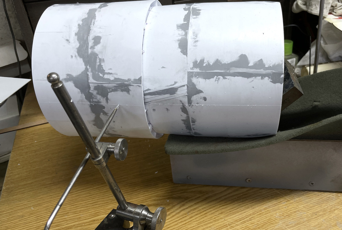
I scribed a horizontal line down the center of each side of the bulkhead assembly using my Starratt surface gauge. i supported the straight portion in a jig I made to support my O'gauge locomotices when repairing them. After scribing the line down the center on one side, I rotated the jig, without moving the bulkhead and scribed the opposite side. I was rewarded with two lines on opposite sides. I then highlighted the lines with a fine Sharpie using a straight edge.

How to separate them. I thought of using a razor saw and quickly dispelled that idea. I had to cut not just the skin, but the inner skins on the doubled portions and all the way through the annual decks. I ended up using a rather large abrasive cutoff wheel intended for cutting steel. When you abrasively try to cut styrene you essentially melt your way through it, but through it I got. The cut was ragged and not particularly straight, but it was within the margin of error and was fixable.

Where the cut occurred where there was no blocking piece right there, the styrene was spreading out. Before cutting the second side, I added new 1/8" stock to bring it right to the cut edge thereby stabiling the edge from further delamination and getting a head start on closing off the edges to simulate the solid armor plating.

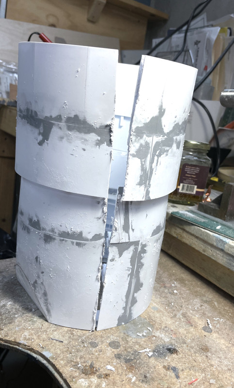
I then cut side two and was presented with two shells that DID NOT COMPLETELY DECOMPOSE. There was some spreading at the exposed corners of the annular decks. 

That aluminum clamp was used (among others) to re-secure these edges so I could glue them. I needed solvent cement; tube cement; and thin, med, thick and gel CA to finally get these springy bits to stay put. I do have fears about them holding up in the muesum envvironment and may need to do something else to ensure they stay attached.

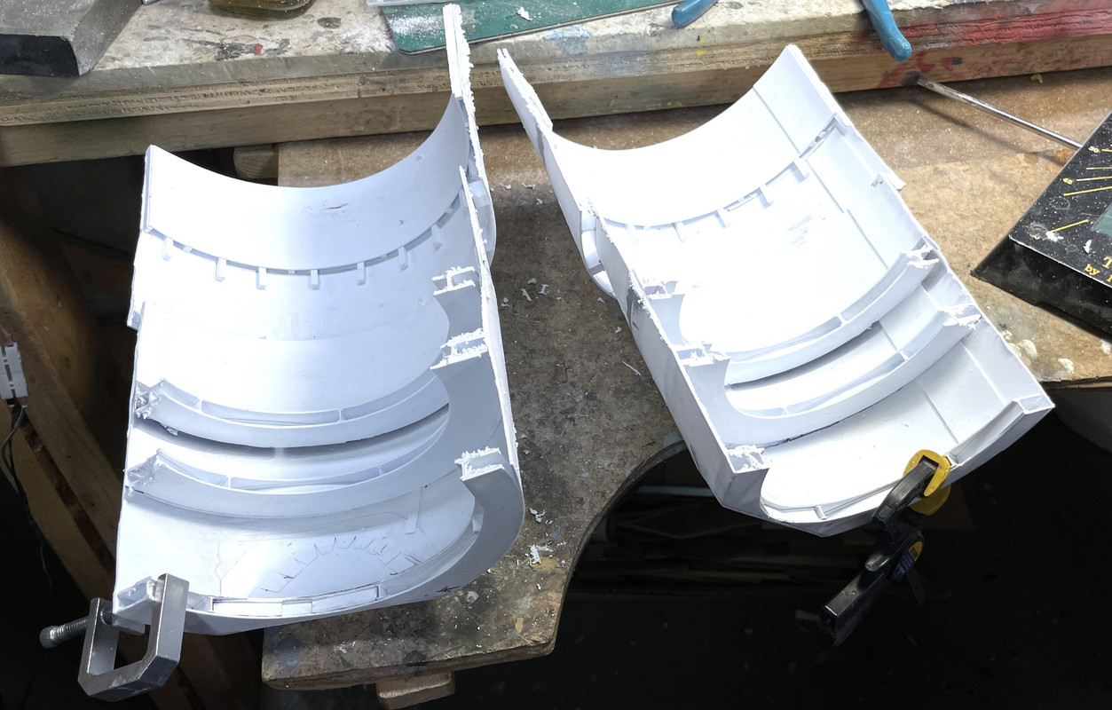
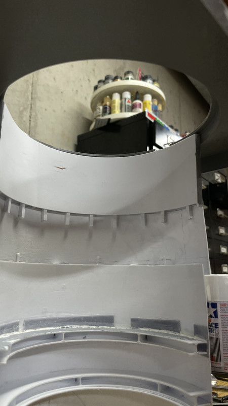
On the open shell, the top will be visible and needed to be closed off to simulate the solid armor. I traced the shape onto some styrene and cut it out using the scribe and snap method (as will all the other pieces).

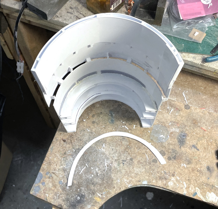
The above picture also shows that the open ends are all filled with stock and sanded flush, but not filled yet. I glued the top strip with solvent cement and held in place with some strips of Tamiya narrow masking tape. This image also shows several other features. I removed the parts of the of the inner-cylinder spacers that were peeking out over the edges of the lower tapered bulkhead to ensure that the ring gear/roller track will nestle in properly. There is also copious amounts of Tamiya filler that will be sanded before painting in the next session.

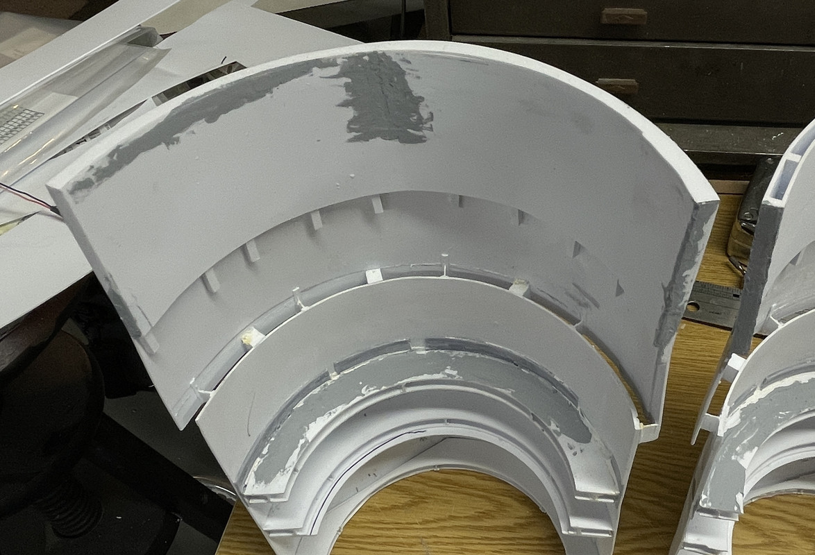
Both shells were now fully filled and rough sanded. Whew!

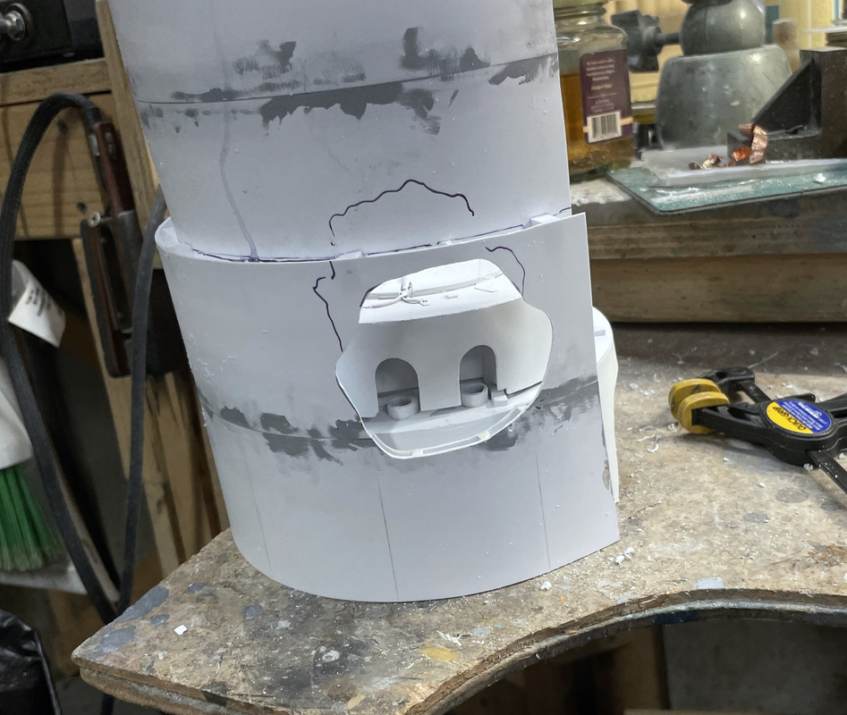
It was also time to open the last cutaway that would expose the pinion gear area. I assembled the structure with the pan deck and electric deck, rotated the shell to the proper orientation and drew the place the opening would go. I used the Dremel with a carbide router to rough out the hole. It too had to penetrate multiple layers, which I then cleaned with a sanding from on the same Dremel. In this image everything is upside down. Because the armor plate doubling will be on the top of the opening, I don't think it will be visible, but I may fill the gaps with Milliput to make it look solid too.

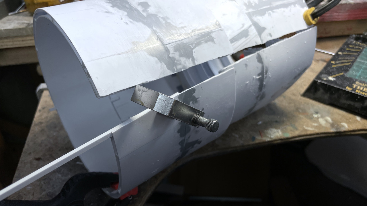
I was finally at a point where I could actually figure out how this was going to go together. I found out that I COULD NOT USE the kit's large deck molding. I was planning on using it, but again, like the rangefinder ears that I didn't draw and therefore didn't include with the width measurements, I didn't draw this part either. And it doesn't work at all. Here's why.

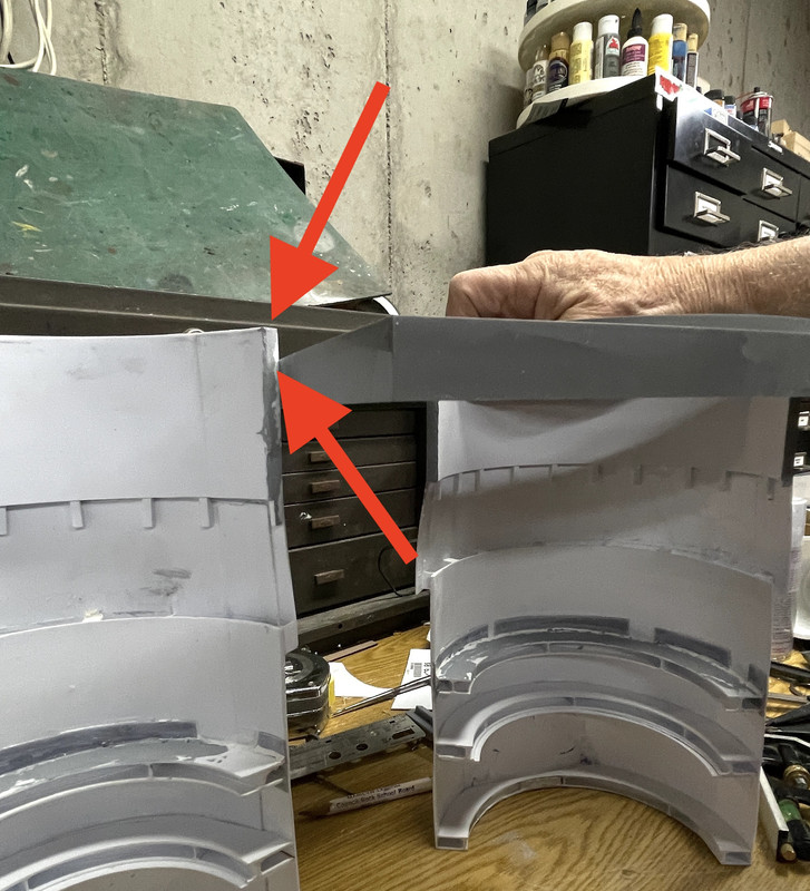
That difference in apparent height, is because the fixed shell slips up inside the raised gun house mounting, but the deck walls and deck and about 1/4" lower. To connect the open shell with the fixed one, I either have to mount the fixed shell lower or cut off the excess on the open one. And both choices create a mess since the bulkhead height is determined by the collective height of the internal decks. This view shows how the deck piece overlaps the shell from below. It looks great snuggled there, but screws everything up.

So I'm not using it. I'm going to mount the lower gun house plate directly on the fixed shell and the open shell now aligns perfectly. I may make a flat deck simulation piece. I found out from Ryan Syzmanski today that the teak decking planks are 5" wide. I might want to plank a piece with real wood stained teak... just think'n.

Here are the shells with just the gun house bottom. And it works!

The last thing was to see if my hinge idea worked. It really didn't. It's not wide enough to provide a good mounting surface.

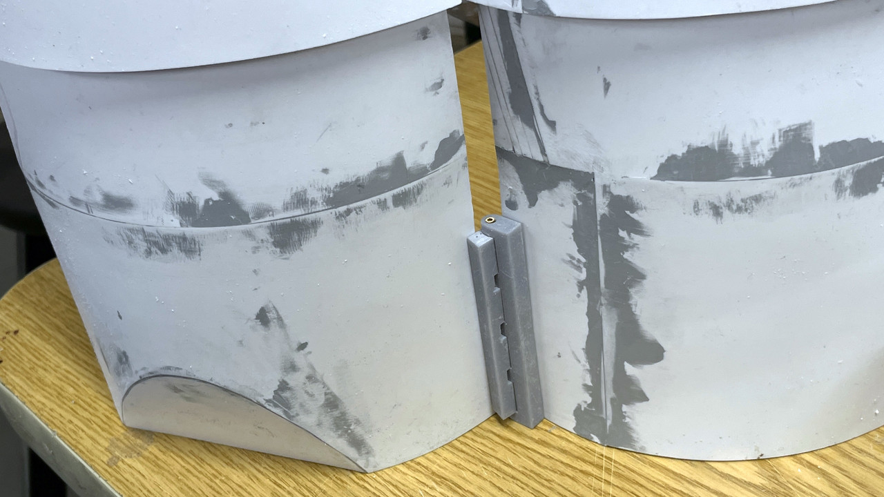
Furhtermore, since these shells are not moving, a hinge is overkill. I'm going to permanently screw the shells down to the baseplate. BTW: the brackets came out well and I will also be mounting them before painting. I'm just going to draw and 3D print an angle bracket that will hold the shells in the correct relationship, and that will be that.

With the shells on their way to completion, all the painting will commence in full. I got a green light to use the spray booth at my wonderful local hobby shop so I can spray the solvent-based paint when the weather isn't cooperating. I've started playing with getting the right shades of gray to paint the apparatus and guns. This is the gun in the un-restored #3 turret and it looks kinda like haze gray to me. I may be able to use it for the guns. For the equipment, I'm going with a darker shade. This is pano that I took. You can see that the door frame is a darker shade than the gun's yoke. I also have to add those ladder rungs you see in the lower left. The gun captain uses them to get up the alcove and out of the way of the maddening 4 foot gun recoil.

So... like I said. it was a heckuva day. I am very relieved to have the bulkheads done. The rest of the job, while painstaking, will be fun.

  • Member since
    January 2015
Posted by TheMongoose on Thursday, October 27, 2022 9:29 AM

What a great read. Filled a work meeting i had with solid content since the meeting was a waste of time lol

cool to see the whole process

In the pattern: Scale Shipyard's 1/48 Balao Class Sub! leaning out the list...NOT! Ha, added to it again - Viper MkVii, 1/32 THUD & F-15J plus a weekend madness build!

  • Member since
    March 2012
  • From: Louisville, KY
Posted by Builder 2010 on Thursday, October 27, 2022 10:27 AM

So glad provided an elightening diversion. I'm am assuming you're working at home...

It took about 5 minutes to draw a new junction piece and it's now printing. My wife and I are having lunch with our daughter today and then I have PT so I may or may not have time for work today, but I will definitely tomorrow.

The bracket is over built (as usual) and I will drill for the screws after it's printed.

  • Member since
    March 2012
  • From: Louisville, KY
Posted by Builder 2010 on Thursday, October 27, 2022 5:17 PM

As predicted, short session today, but did get some stuff done.

Here's the printed junction block. I have some clear space on the other side of the bulkheads to put the mounting screws. It's way stronger than it has to be.

Because I drew this part directly in conjunction with the bulkhead drawings, I was able to build in the curvature on the back (both legs). You place the part INTO the other shape and "Intersect Faces". What your left with is a line or lines of exactly where the two surfaces intersect and you can then shape the part to that line. The curves matched perfectly. While it's not essential in this instance since I'm relying on screws and nuts to hold it, having perfectly matched surfaces is great if you're going to glue them together. With the screws, having the surfaces matched will not introduce any stresses to straighen out the curves.

Also, here's the finished mounting bracket(s). There are two of them. Between the massive junction pieces and the mounting brackets, plus the secure mounting of the central column, the model should be pretty secure.

I spent some time sanding and finishing the filler that I applied yesterday. I got one shell done. I will finish the other one tomorrow and maybe, just maybe might be abe to get the primer put on tomorrow. The weather is looking pretty good being in the mid-60s and sunny.

I also took time to clean off the workspace in preparation for painting everything. It was an unholy mess. They say, "a clean desk is the sign of a sick mind." So what's the opposite when it comes to work benches?

  • Member since
    March 2012
  • From: Louisville, KY
Posted by Builder 2010 on Friday, October 28, 2022 6:02 PM

Weather cooperated this afternoon with temp at 68° F and a little breeze, so after doing some more work on the shells, I DID get to prime them.

I located and attached the base mounting brackets. Having the shells sitting flat on their bottoms, I marked the upper hole location with a Sharpie and drilled a small 1/32" pilot hole. I opened the hole with a 4mm drill. I'm using 4 X 8mm hex-button-head screws and nuts. I fastened the top screw and then drilled the bottom through the bracket's hole. I was able to accurately located the lower hole by shining my work light through the translucent styrene so I could visualize where the annular decks were.

I fastened them in place in prep for painting.

I then positioned the center junction piece and again marked one hole on one leg. Did the same drill routine and mounted the one side with one screw and then drilled the second hole. I fastened the one side, brought the other shell into position, marked its first hole and then repeated the drill.

I mounted the bracket permanently and painted the shells with the hardware in place.

And the interior view;

Notice in the above, I added some cover pieces on the open ends of the annular decks. I didn't like how ragged they looked AND there was some epoxy filler in some that was very hard to remove. The viewers probably won't object to this. I also broke loose one of the decks when I was applying pressure on the structure during the drilling/screwing operation. I was worried about the structural integrity of these joints and my fears were well-founded.

Here's the outside of the just primed shells. I couldn't really see the piant laying on. I was wearing my chemical respirator AND safety googles besides my normal glasses, and couldn't see much of what was going on. Ergo, I got some runs. White is a tough color to spray for that reason. I smeared the paint with my nitrile-gloved finger to reduce its height and will do some post-priming finishing to restore the surface before finish coats.

And the insides,

And I even started masking the rotating decks. I got the powder flat and the first projectile flat masked to paint the deck portion. The powder flat gets a linoleum brown and the projectile flats gets burnt iron since they are bare steel. The inner portion might be linoleum or painted steel, but the rotating parts are bare steel with heavy coatings of grease so the projectiles can be easily slid to the hoists.

Have a great weekend and Happy Halloween for all those readers who live in places where this is celebrated. In Louisville, Halloween is a big deal, in many casse more so than Christmas. There's a street, Hillcrest, where the decorations are so over the top, that 1,000s of people visit there. When the houses are sold, the decorations are conveyed with the property and the new owners are honor-bound to keep it going.

  • Member since
    August 2007
  • From: back country of SO-CAL, at the birth place of Naval Aviation
Posted by DUSTER on Monday, October 31, 2022 2:10 AM

Whew! Good job, the new braces look like they should hold up a massive steel gun turret.  Yes

Steve

Building the perfect model---just not quite yet  Confused

JOIN OUR COMMUNITY!

Our community is FREE to join. To participate you must either login or register for an account.

SEARCH FORUMS
FREE NEWSLETTER
By signing up you may also receive reader surveys and occasional special offers. We do not sell, rent or trade our email lists. View our Privacy Policy.