SEARCH FINESCALE.COM

Enter keywords or a search phrase below:

Takom 1:35 AH-64D Apache State-to-Finish Build

5103 views
14 replies
1 rating 2 rating 3 rating 4 rating 5 rating
  • Member since
    March 2012
  • From: Louisville, KY
Takom 1:35 AH-64D Apache State-to-Finish Build
Posted by Builder 2010 on Wednesday, July 19, 2023 9:22 PM

After the success I had in building (and blogging @ https://cs.finescale.com/fsm/modeling_subjects/f/16/t/187540.aspx) the Kitty Hawk SH-60b Seahawk, I was excited to tackle the Takom kit when I read about its release. Like the SH-60b, this is a large scale model meaning that all the cool helicoptery things—like complicated rotor mechanisms—would be highly detailed and "fun" to build. The Takom kit does not disappoint. I chose the Longbow version because it's very cool, and is an effective weapon in the US arsenal.

I tend to pick plastic kits based on a few criteria that I've had since I was a kid building a model a week: high parts count, fat instruction book, lots of decals... and a neat subject. This model checks all those boxes. Along with that complexity comes lots of fussing and potential frustration, but hey... as my wife reminds me all the time, "Stop whining! It's your hobby. Nobody's telling you to do it."

As a very modern kit, there's wonderful surface detail and texture and should look great. And also because it's a very modern kit with state-of-the-art molding technology it has parts that are almost too fine to handle, install and hold up in handling. A perfect example is the hand grabs. The instructions tell you to attach them very early in the process. This will guarantee them being broken off many times before the build is complete. Furthermore, even installed later, their survival is dubious at best. I will change them out for bent wire, which I had to do on the SH-60b for the same reason. This time I won't even attempt to use them first, I'll go right to the metal.

In the SH-60b build, I also purchased the Reskit detail-up components (Rotor Head, Rt Hand GE T700 turboshaft engine, Tail rotor and Rear End Hinge assembly). The T700 in this model is nice enough to use and, more importantly, won't require any extra surgery to get it fit into the plastic model's airframe. I'm also forgoing any aftermarket parts for the rotor head, for that too seems to be very intricate out of the box, and much is hidden under housings so the work is never seen.

I may splurge and order the Reedoak resin pilot and gunner figures. They are stunning and would be a great asset. I will super-detail whatever is practical and will be seen. I don't want to go down the rabbit hole of detailing invisible parts of the model.

Today I officially got started. I unpacked the sprues and installed them in my fancy, homemade sprue holder. I carefully crafted this out of scrap cardboard and a hot glue gun. The kit's part count is high and it fools you since the sprue holder has a lot of the alphabet unused. Lots of parts on some of the sprues. The SH-60b used more slots as did the RyeField Sherman A3M2.

So stay tuned faithful readers. This should be a good one. The fellow that did the review in this fine magazine spent 150 hours building his and I do not believe that he added the vast amount of piping and wiring this model could display. The kit has a bonus "blade folding" kit, so the blades can be realistically folded. I will need this (as I did on the Seahawk) since I don't have the shelf space for a fully unfolded 1/35 large chopper. I didn't know they folded, but imagine it's a lot easier to stuff this bird into a C-17 with them in that configuration.

  • Member since
    April 2003
  • From: USA
Posted by keavdog on Wednesday, July 19, 2023 10:23 PM

Great subject Myles.  I have the 1/48 Hasegawa kit in the stash so I'll be watching.  Always fun to watch you work your magic on your builds.

Thanks,

John

  • Member since
    February 2003
  • From: Between LA and OC, SoCal
Posted by oortiz10 on Wednesday, July 19, 2023 10:32 PM

Oh man! This one will be greater than the sum of my two! I'm looking forward to following this one.

Good luck!

-O

-It's Omar, but they call me "O".

  • Member since
    December 2002
  • From: Valrico, FL
Posted by HeavyArty on Thursday, July 20, 2023 8:08 AM

This will be fun to watch.

Gino P. Quintiliani - Field Artillery - The KING of BATTLE!!!

Check out my Gallery: https://app.photobucket.com/u/HeavyArty

"People sleep peaceably in their beds at night only because rough men stand ready to do violence on their behalf." -- George Orwell

  • Member since
    March 2012
  • From: Louisville, KY
Posted by Builder 2010 on Thursday, July 20, 2023 7:27 PM

I promise not to disappoint. Some of these threads will have repeat themes from earlier ones, so if you've read all of them, please forgive me.

Construction in earnest started on the Apache. You're presented with a challenge right from step one... painting. The model does not call out colors. I downloaded many Apache images including a raft of them about the two cockpits. Based on the pics, the entire space is basically NATO black. The side control panels are a medium gray background and most switchs/knobs are light gray.

If you just follow the instructions in order and build the entire cockpit, you will be challenged detailing and getting paint where you want it. I'm building it up in sections that will be painted and then installed. Of course this adds some extra work removing paint where the glue is going to go, but it's the price you have to pay to get good access. 

The first step has you building up the tub.

The gunner's (front) rudder pedals are out in the open and easy to put in now. The pilot's pedals are going to be shielded by the center bulkhead. Therefore, hold off putting in the bulkhead until you get the pedals installed. It's easy to want to put that structural piece in first, but resist it.

Part M20 goes on the outside of the tub, but the instructions were difficult to determine this. After fussing with it inside, I did some lateral thinking and said to myself, "Where else could this go?"

The moldings are very precise. Parting lines are almost non-existent, but the sprue attachments are a bit robust and require a lot of slicing and sanding to remove. Ejection pin marks aren't bad either.

The 2nd part was the first piece of PE of many. There's quite a lot of PE in this model; four frets including one for the blade fold project. After advice from Brian Bunger, the propietor of one of the best hobby shops in the USA; Scale Reproductions, Inc., I apply PE using Gel CA. It stays where you put it. You can apply tiny amounts. And it cures slowly so you can actually move the PE around to position it without it kicking halfway through. When you get the part where you want it, a small brush with a small amount of accelerator and it kicks. This was a kick plate for a vent, I'm assuming.

The next parts were the collective pitch control and throttles. The mounting end of the CP is an angular piece where the sprue was attached. Be careful when you de-nub this part to maintain the flat mounting surface at the correct angle. The trottles are tiny and again, careful de-nubbing ensures there is a mounting tab left to glue into the side panel.

These parts are very exposed and delicate so I could wait until I got the rear and side walls in place to protect them.

Left side and rear:

And the right side:

The color of the quilted padding appears to be the same color as the rest of the cockpit as can be seen in the overhead panel.

The seats and cyclic pitch stick were next. These I chose to leave off until the tub is painted. The seats obscure too much of the interior. They glue in with two pins and shouldn't be any problem to install.

Three key pads go in next. These had distinct mounting features and you can't mix them up. The kit has screen decals, but no other buttons. These will be hand painted. While there are keys on these details, their relief seems shallow so making them distinct won't be easy for me.

The gunner's control console is a separate build and installs in a large notch at the tub front. While I debated not installing this, upon reflection, it doesn't block much and I chose to install it. Afer installing I added the details.

I work on models with high and tiny parts count with my "parts catcher". It's a piece of cloth stapled to the underside of my work table, draped over my lap and then clothes pinned to my shirt. This doesn't catch everything, but parts that drop straight down are caught. I have two walls on my work table on the back and right sides to block flying parts that head in that direction. There's still open sky and other ways for parts to enter the quantum rift, but I've mitigated some of the avenues.

Here's the drape.

And here's a part that it caught (among others).

And here's where that part goes.

I don't know what that part is. It faces under the control panel and won't be seen.

Two more parts went onto the gunner's console: His trigger controls. They're identical and were a pain in the butt. Sometimes little stuff can drive you nuts.

Last thing I did required another decision. There is a transparent armor glass shield between pilot and gunner's compartments. The instructions have it going on now, but that would be a problem with painting. But there is a plastic wing attached that should go on now for better gluing reasons. I chose to mask the glass now and install it. I can then paint the tub without worrying about it. This assembly also will go on as a subassembly after tub painting.

Till tomorrow...

  • Member since
    March 2012
  • From: Louisville, KY
Posted by Builder 2010 on Sunday, July 23, 2023 4:19 PM

Finished the tub as far as I could go without painting stuff. My decisions to keep it open for access for airbrushing and detail work seems to be correct. I was having trouble with my various tweezers holding small round objects so I took another pair and made a small mod with a diamond burr and the Dremel. The group grips nicely and the parts don't go "Sproing!" all over the shop.


I put the parts on my Ed Tackett designed parts holder and shot them with NATO black. I painted the tub holding it in my hand.

While this was all drying I drilled the openings in the fuselage sides based on the instructions for this particular iteration of Apache. The sides had a few sprue attachments that needed snipping and cleaning. I test fit the fuse sides together to get an idea of how they mated. They mated well!

Two drills were called out: .7mm and 1.0mm. I used the English equivalent of them and drilled them out and lightly deburred the outside hole. One of the holes had to be drilled at the junction of the two hull sides. I hand-held the sides and drilled the hole successfully.

I hope everyone is having a nice weekend. Here in Louisvile we're having wonderful weather for a change.

  • Member since
    March 2012
  • From: Louisville, KY
Posted by Builder 2010 on Monday, July 24, 2023 5:53 PM

After viewing the videos and reading reviews it was quite clear that decals would be a problem. I chose to use the screen decals for the instrutment panels. To ensure the thick carrier film was not a problem, I used the #11 blade to slice through the film to separte the colored part of the decal right at it's demarcation line. I didn't cut all the way through the decal paper since you need something to hold onto.

This let the decal sit nice and tight against the screen boundary. I used Tamiya clear as a base coat for the decals and then, after application, Microscale Microlsol. They did settle down nicely.

I'm not gloss coating the screeens. They are not glossy in real life. After decal application I started the detail painting. The panels ARE NOT colorful. There is very little color other than matte black and light gray. I painted the knobs Tamiya sky gray, and the tiny toggles just a touch of Molotow chrome. The dots are so tiny you can't tell what color they are. If fudged the three steam gauges to the right of the pilot's rt hand screen.

I painted the seat cushions off the seat pans and when dry glued them together with Testor's tube cement.

Tomorrow I will go back and do some light weathering and wear marks on things. I still have to order the Reedoak pilot and gunner figures. 

While that was all drying I started on the complicated and very delicate rotor head. I already broke one of the very fine extensions on one of the parts. I don't actually know when it broke. One minute it was there and the next gone. Much of the rotor is completely hidden by the fuselage fairing so I don't know if it's critical to replace it with wire. I have the skills to duplicate that portion of the part. I'm just not sure it will be worth the effort.

The instructions for this portion are difficult to interpret and I trial fit it together multiple times before I understood just how it went together. The cylindrical part's spindle is slightly oversized for the hole and in attempting to push them together was probably what broke that tiny rod. I should just open up the hole with the properly sized drill. I did attempt to slightly reduce the size of the pin.

As I was starting to get frustrated and it was dinner time, it was a good time to quit before I broke anything more. I'll tackle it again tomorrow and probably will re-make some of the tinier rods out of metal. Styrene doesn't work for everything!

  • Member since
    March 2012
  • From: Louisville, KY
Posted by Builder 2010 on Tuesday, July 25, 2023 5:54 PM

I did drill that tight pin hole larger so it would no longer be a press fit. It was a #54 drill. I then made a metal connecting rod to replace the missing one. I first had to cut out the remains of the existing rod to leave an open clevis to accept my homemade part. To make these kinds of things, I take the phos-bronze or brass wire and crush an end flat in the powerful jaws of a Vise Grip. My vise grip was my dad's and is probably 60 years old. They don't wear out. I squish it in the jaws while tightening the screw until it gets as thin as I want it. I turn it over, clamp in different places on the on the jaws so the piece is flattened evenly. Since this piece needed a round end with a little bit of thickness, I added some solder on both side. Final shaping was done holding the shaft in a needle nose and filed both in thickness and width. I rounded the end. 

I used a scratch awl to make a fine center punch mark and used the 0.022" carbide drill to create the pin hole. The other end, after capturing the length for the existing one, had the same treatments and then a piece of rod soldered in to simulate the pin on that end.

I had to drill the bracket with the same drill to accept the pin. I first cut off the fake pin's nub and filed it flat so it would accept another center punch mark for an accurate drilling. I had to further reduce the radius of my rod's end so the two holes would align and accept the real pin.

Putting that vertical lever on was a challenge and the glue joints of the cross pin kept breaking loose. I finaly got it together and decided to let in cure fully before finishing the assembly tomorrow (or wednesday). My younger (19 year old) grandson and I are installing a new garbage disposal. Depending on how long that takes will determine how much shop time I'll get.

Waiting in the wings is another part of this complex set of swinging levers and frames that provide the cyclic and collective inputs to the swash plate on the rotor shaft. Helicopter mechanics are something else! This drawing, like others, is misleading. The leftmost arrow descending down from part F41, does NOT interact on that pin on F39. It falls way wide of it. I'm assuming that arrow just shows the direction the part must be assembled. I've read complaints about the instructions and they're not wrong.

Till tomorrow.

  • Member since
    March 2012
  • From: Louisville, KY
Posted by Builder 2010 on Thursday, July 27, 2023 11:52 AM

With a fresh start I tackled this ridiculously complex and fragile rotor head. I had just played guitar for about a half hour. I'm very out of practice and pledged this weekend that I'm going to start playing again to build up my strength and callouses. I was inspired after seeing an old Austin City Limits show featuring Stevie Ray Vaugh (RIP) at his last appearance in 1989. Why am I telling you all this? Because the exercise and being a little low on blood sugar left me with very shaky hands and I was about to finally assemble the lever bracket assembly I started yesterday.

I have a ton of images today, and a lot of dialog since this was one heckuva session, so strap in... And paraphrasing the words of Obi Wan Kanobi remarking on the Tatooine Cantina, "things could be a little rough"!

After trimming the homemade link a scosh more I was able to get is all together. I ended up drilling more 0.022" holes and pinning the final connection instead of relying on the tiny plastic protrusions. It's now a reasonably stable assembly.

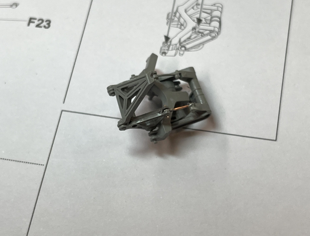
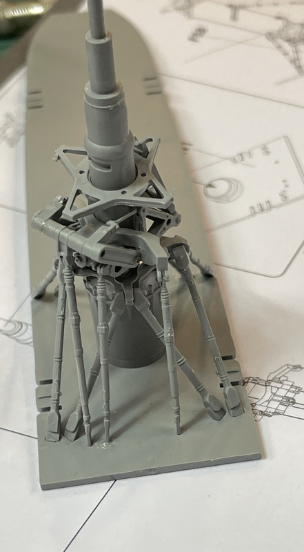
After this, there is a mast base and rotor head plate (don't know what to call all of these sub-parts). Around the mast go a sequence of angular trusses that brace the rotor head. Each is different in their upper connection helping to avoid getting them in the wrong place. They fit nicely and caused no trouble. It lulls you into thinking that this could all go together easily. Wrong!

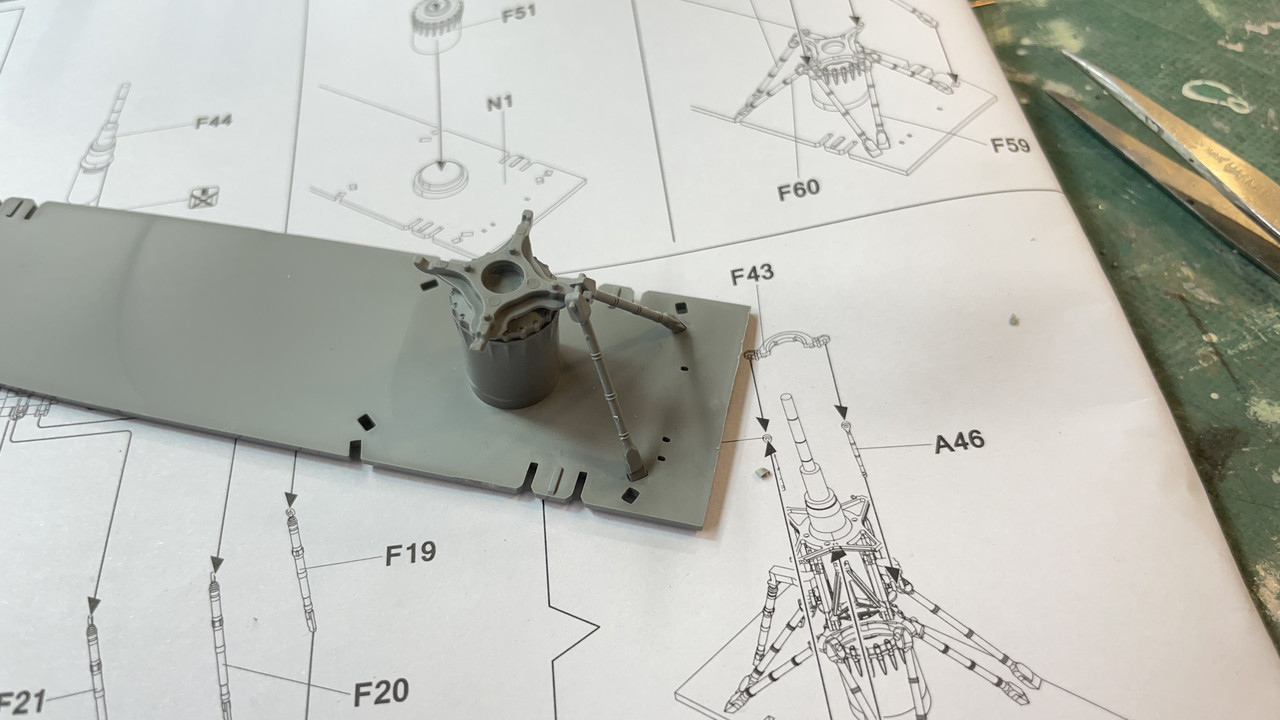
Here was the first one. I cut each individually off the sprue, cleaned it up and attached it before doing the next, just to keep things tidy.

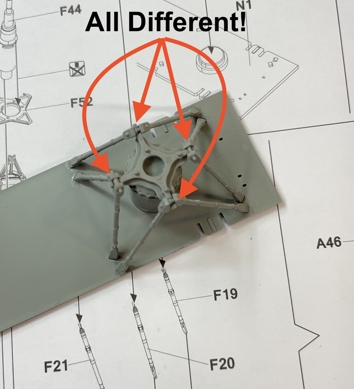
Here's the complete array installed. Note that the upper pin area is different for all four so even if you're confused, if observant, you could figure it out.

Yesterday's assembly attaches to this with two plastic pins. At first I didn't glue it, not knowing for sure how it would settle in, but later felt it was okay to fasten it since it was moving around too much and not helping at all.

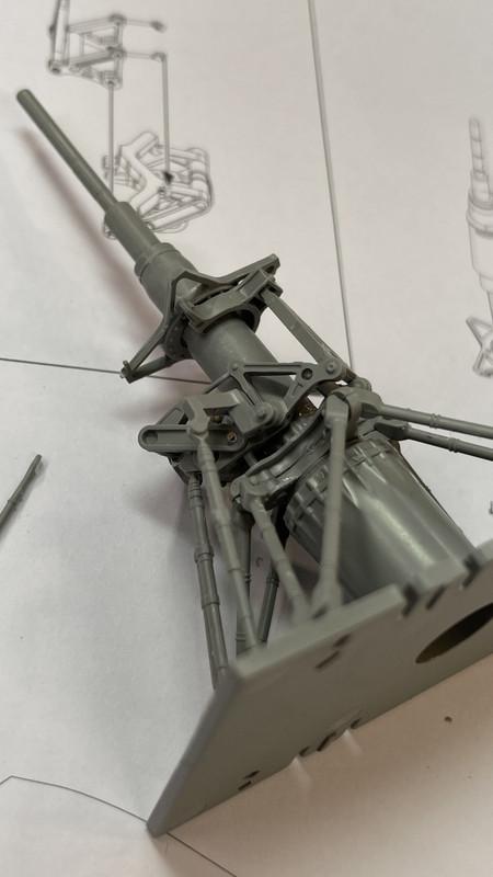
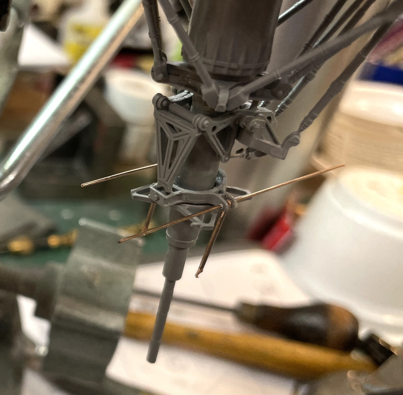
When this was installed the three operating links went in. These were very fragile with the upper clevis end almost being to fine to work. Comparing it to the #11 blade shows the lack of mass quite well.

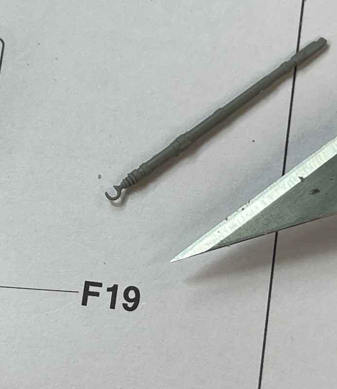
Amazingly, all three links went in without hassle or breakage.

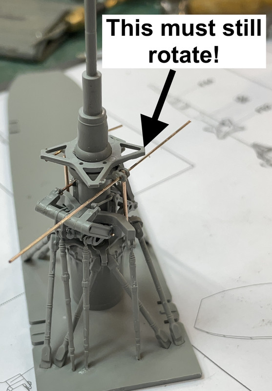
The mast then slipped in between and glued into the base with a key to align it. BEFORE PUTTING IT IN PLACE YOU MUST PUT PART #F52 ONTO THE MAST. This part is supposed to be NOT GLUED. That's a real challenge as you're suppose to install swashplate parts below it and they must be glued. 

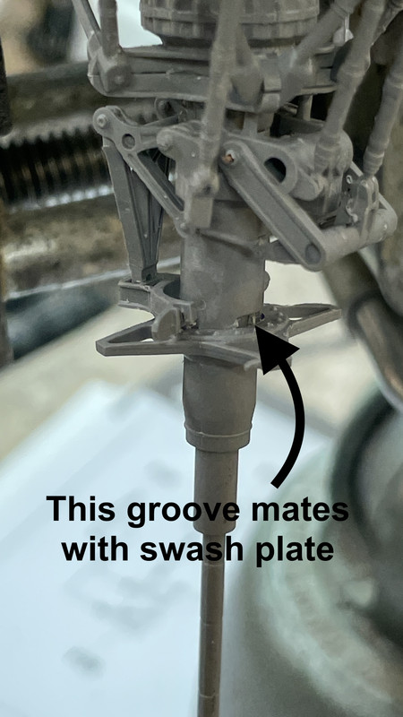
Just underneath the rotating connection plate (possibly for the collective pitch) went a two-part swash plate (term??) with two frail links that tie into the lever assembly installed earlier. The swash plate without the pins goes in first and engages another lever in this assembly. This was a horror, but not the worst horror. You are supposed to glue it in place WITHOUT gluing that collective plate above it. My first attempt with liquid cement did just that...glued it! I was able to spin it enough to break the not-complete-bond and get it moving.

There is a lug on the i.d. of these two shells that is supposed to engage in a similarly shaped slot in the main shaft. They are different sizes so you can't mix up what goes on which side. As I fussed with getting the rest of this in place, it kept breaking loose... over and over and over...

Then came the real horror show. The last one was just a "coming attraction". In addition to putting the second shell in place into its rectangular slot, you must also captivate two tiny connecting links.

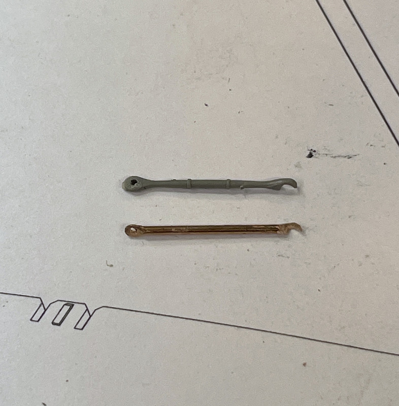
Attempt #1: I glued the two links into the pins on the non-attached shell and tried to manipulate it into position while catching the lower end of these links into another clevis on the lever mechansim. Not only didn't it work, knocking the previously installed shell off, but it ended up breaking one of the links in half. I then crafted a replacement matching the length and design of the two ends: one enclosed and one with an open slot.

Attempt #2: Same scenario except this time one plastic and one metal link fell off.

Attempt #3: Plastic link #2 gave out. Getting a bit scary now, isn't it?

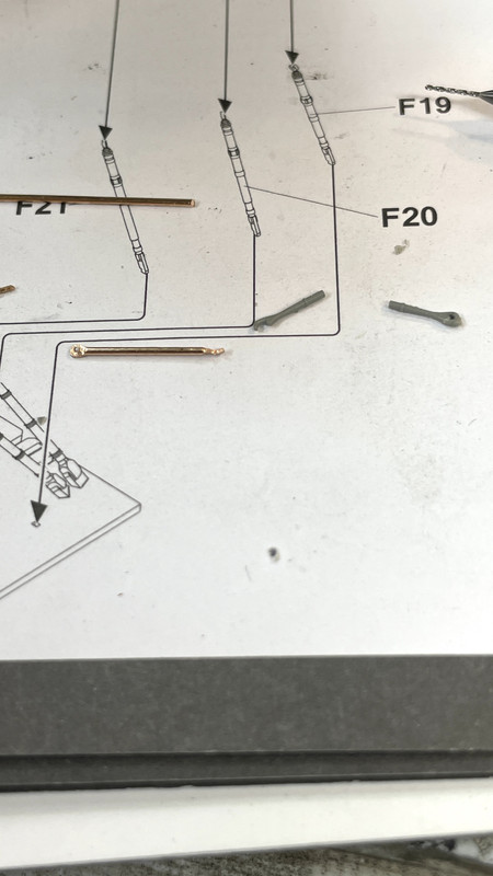
With my vast experience making metallic links, I quickly crafted another the same length as the first one.

I then made a couple of changes so I wasn't doing the same thing over and over again expecting a different outcome. Hey! I'm obsessed! I'm not crazy! 

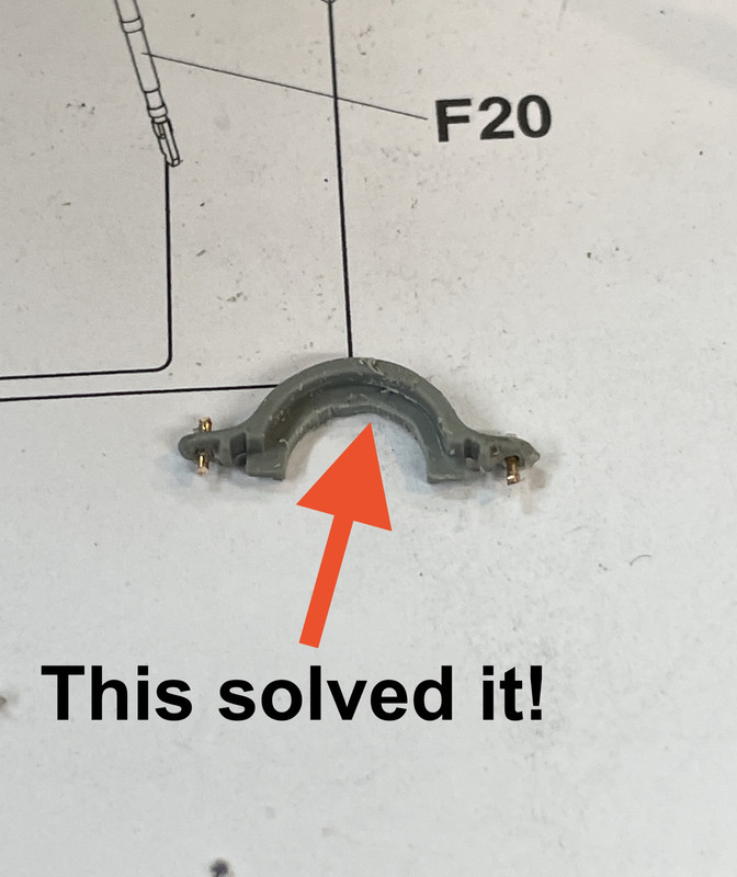
I also removed the rectangular lug on the one shell that I was having trouble installing since the lug was not fully entering the mating slot and was preventing the two shells from meeting properly.

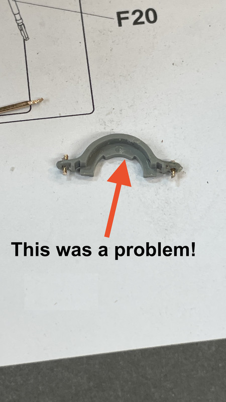
Here's the slot that wasn't working.

Problem solved! This shows the short pins which I subsequently abandoned.

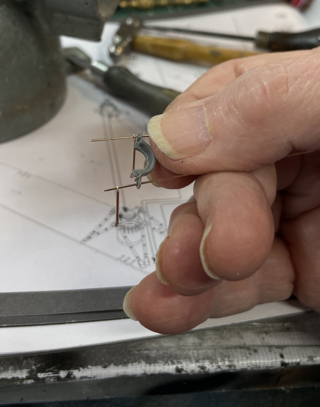
I also realized that attempting to hang the links on those tiny plastic pins and expecting it all to hold together as I kept manipulating the parts simply wasn't woring. I drilled the plastic pins out of the one shell and fully drilled out the dimple ont the other. I originally cut the metallic pins correct length, but this was just as hard to assemble as with the plastic pins. I wised up and used long pieces of 0.022" phos-bronze that I could thread through both shells and then guide them together. 

Once I got all these mods in operation, I was finally able to bring all the parts together. I brought then into engagement gradually, making sure that the links were engaging their correct clevises in the lever block.

Once I got the two halves positioned, I was able to swing the links up into engagement without worrying about all the parts falling into my parts catcher.

Here's the reverse view showing the lnks into their respective locations. You really have to master the skill of drilling tiny holes in akward places to do this work. BTW: my hands steadied out after a snack and some Gummi Bears.

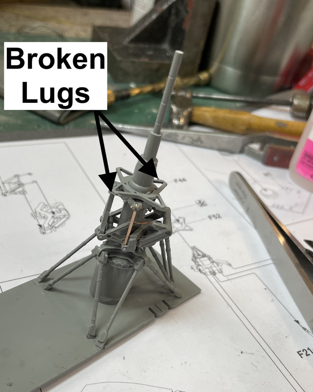
And here's the fully assembled lower control end of the main mast. There's another crisis waiting around the corner. That upper rotating part has two little ears with slots to receive other links. Both of these ears have one half broken away and will need to be replaced. I believe I can either form it with Bondic UV curing resin or make it out of PE fret material. Either way, I'll get it fixed.

That last bit took well over an hour to resolve. I can see why some folks are just leaving all this stuff off the model since it's out of the sight line. I also can imagine that a lot of modelers just don't have the experience making these small jewelery-like parts. If I had it my way, I'd replace all the plastic links with metal. I believe when Neil on videos got to this step, he wrestled with it all off camera. Granted, my metal links are a bit simpler in design than the kit's, but when painted, no one will notice. I had to do this a lot of the Seahawk too for the same reason. If I had a swiss-type lathe that can turn tiny long parts, I'd machine them all.

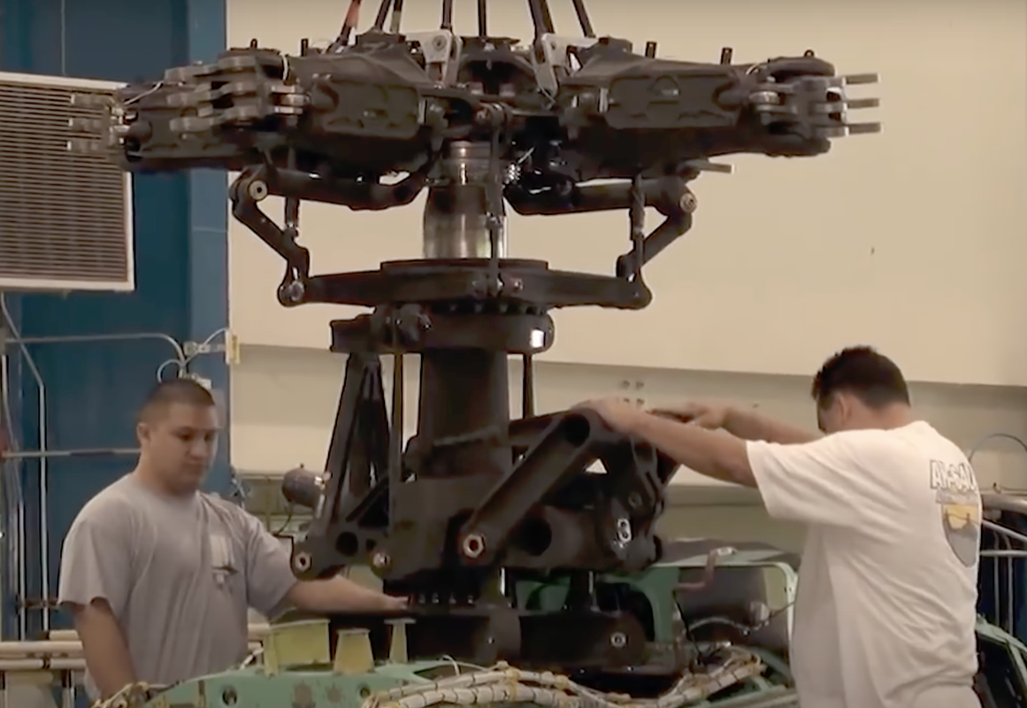
I think this assembly has reached the point where it can be painted. I believe it can be painted all NATO black. Part of the main shaft is polished steel, I will try and use Bare Metal Foil for this part. When you look at the mechanical complexity of a helicopter you wonder how they ever fly at all...

The color looks pretty dark. Anyone have accurate data on the rotating parts color? In this image it looks awfully like Olive Drab... Also note the polished portion and shiny ends of fasteners and link bearings.

I'm glad this part is over. It was truly a challenge!

  • Member since
    March 2012
  • From: Louisville, KY
Posted by Builder 2010 on Thursday, July 27, 2023 4:57 PM

After airbrushing the rotor head and deck Tamiya Olive Drab, I prepared some thin aluminum foil to finish the steel portion of the rotor shaft. I have some German Aluminum foil that's very thin. That roll is over 20 years old and came back with us when we repatriated back from our German sojourn in 2002. It's thinner than standards Reynolds. I didn't have bright polished Bare Metal Foil. I do have the matte aluminum, but didn't want to use it in this application.

To make the foil adhesive, I coated it with old standby Microscale Foil Adhesive.

I actually measured the different areas area with a dividers and made each strip long enough to overlap the ends with reasonable extra. I then picked out all the shafts and pivots with Molotow decanted chrome with a very fine detail brush. I buy eyeliner brushes from Amazon to do this. They are very cheap, about $8.00 for 100 of them. They're impervious to solvents and when they don't work well anymore I throw them away. I like how this turned out. As I noted, the metal links do not look out of place now that they're painted.

I tried this assembly into the fuselage. The piece keys into the side with very positve lugs, and the cockpit locates well too. As you can see, you can't see much!

A lot has to happen before I button up the fuselage, but it was worth checking. I also did the final treatment to the cockpit and glued it together. I did very light weathering on the edges, rudder pedals and gloss coated the screens. I had trouble getting the masking tape off the lower edges of the armor glass dividing panel and scratched the clear styrene. I brushed a coat of Future on it to hide the scratches. I also put a wash on the seat cushions. I know there are aftermarket items that could even notch the cockpit up a level, but frankly, it's seems sufficient out of the box.


The seat cushions are nothing special. i wish there was some more texture to them. The left seat has the wash.

Then came the kit's PE seat belts. There are no instructions on their use. I first treated them in vinegar to micro-etch the surface to accept paint. I then treated them with JAX brass brown treatment which also chemically treats the surface. 

I then hand painted them neutral gray. Photos show that these belts can be gray.

I have no idea just how they're going on, and I'm not a big fan of PE seat belts since they can have a mind of their own. I supposed I could have annealed them beforehand so they would be soft enough to conform to any shape I want, but I didn't. Wish me luck. I'll molotow the hardware after bending.

While I was waiting for things to dry I was re-watching Nigel's AH-64E buildk and was catching some more hints. He really went out of sequence on some things that seem to work. He installed those swash plate on the mast before installing that into the rest. That would have helped alot. So make a note of that. INSTALL SWASH PLATE HALVES BEFORE ATTACHING MAST TO REMAINING ROTOR ASSEMBLY!


  • Member since
    March 2012
  • From: Louisville, KY
Posted by Builder 2010 on Sunday, August 13, 2023 6:30 PM

I haven't done any Apache work for a while. If you're following along on the 5"38 project you can see why I haven't. I also haven't done any work becuase I needed those seat belts. Thanks to a tip from one of my readers, I got these on eBay and they'll be perfect. We're heading out for a week trip on Tuesday so work will begin again after that. They're just was the doctor ordered as long as I don't lose any of them.


  • Member since
    July 2015
Posted by MR TOM SCHRY on Monday, August 14, 2023 9:47 AM

Your progress is moving along and your detail work looks amazing!  I guess that I'll be selling my old 1/32 Revell Apache kits and I'll be getting a couple of these kits.

TJS

  • Member since
    March 2012
  • From: Louisville, KY
Posted by Builder 2010 on Monday, August 14, 2023 5:45 PM

I'd hold off making any rash decisions until I get further along. This kit is highly detailed, but it seems to be pretty challenging.


Installed the new belts today and they are vastly better than the pathetic PE with the kit. I don't know why Takom bothered to include it. It might have been better to mold them into the seats. 

Here's a nice comparison: I won't tell you which is which. You can figure it out.

With the belts installed I was able to finally mount the seats. By default and installing the fancy seat belts, I'm saving my money and not spending $50+ on the wonderful Reedoak crew. I'm building the 5" turret and need to keep my powder dry to cover the costs of that project.

I then got back to work on the fuselage. 

Based on Nigel's video, he found that Part P25 which is installed on Page 20, must be installed on Page 5. You can't put the duct assembly in place without P25 being in place, and it's not an easy part to install requiring some pushing and shoving.

Here is part P25 glued to the exterior.

The fit was a bit ragged and needed a tad of filler. Then you assemble the 2-part duct and insert it from the rear. It's supposed to nest tighly into the open space on the outside, but couldn't quite get there. This is what the fit it looked like.

Here's how it looked after filling and sanding.

And here's the ducting on the inside. This ducting is for an APU and the starboard side is the intake I'm assuming.

There's similar opening on the port side which I'm assuming is the APU's exhaust. However, nothing is mentioned on page five. It shows the assembly going in on page 19 FROM THE OUTSIDE. Again, it's tricky fit that would require handling the model a lot and there's internal ducting (Parts C11 & 12) for this one too. I decided to install it now for the same reasons as the opposite side.

I assembled the three parts with the duct glued to the exterior fairing C60.

T DOESN'T GO IN WELL FROM THE OUTSIDE. If you do try and force it, the duct doesn't bend around the corner and breaks the glue joint. Experiece talking. So I did it like the previous one and install the fairing on the outside and the duct from inside. Further reason to install in on Page 5. Page five is where you join the fuselage halves.

Here's the outisde view: The duct has a tiny gap. I'm thinking that all of this is going to be hidden by the engine exhaust housing.

And from the inside.

The last thing I did was install the tail rotor gear box housing. You need to install this BEFORE joining the halves. It has a small fairing and a small PE screen that goes in. All this done before gluing it in place.

It's installed in the starboard half. There is a plastic tail rotor shaft that also goes in before closing it up. I'm not happy with the plastic and may turn a piece out of brass that should not break when you look at it. The vertical fit is excellent. The fore and aft fit looks a tad long, and I will shave it down when it's fully cured.ng. This is the insde view of the starboard half.

And the exterior.

We're heading out for a week trip Back East, so any work will have to wait until then. Happy modeling!


  • Member since
    April 2003
  • From: USA
Posted by keavdog on Thursday, August 17, 2023 9:35 PM

Looks like they are doing another release with very nice pilots.

https://www.themodellingnews.com/2023/08/135th-scale-ah-64d-apache-block-ii.html


Thanks,

John

  • Member since
    February 2021
Posted by JimC2020 on Friday, August 18, 2023 8:59 AM

Wow! This looks super cool! Great job!

JOIN OUR COMMUNITY!

Our community is FREE to join. To participate you must either login or register for an account.

SEARCH FORUMS
FREE NEWSLETTER
By signing up you may also receive reader surveys and occasional special offers. We do not sell, rent or trade our email lists. View our Privacy Policy.