SEARCH FINESCALE.COM

Enter keywords or a search phrase below:

A6M Zero's central drop tank attachments

5339 views
42 replies
1 rating 2 rating 3 rating 4 rating 5 rating
  • Member since
    February 2023
  • From: Indiana
A6M Zero's central drop tank attachments
Posted by buitre on Tuesday, February 28, 2023 1:21 AM

After a Zero ejected its drop tank, what was left under the plane?  I have read that there was nothing left protruding.  But were there any visible holes left?  Some photos show a small rectangular hole immediately in front of the front main spar, and an also small keyhole-shaped hole slightly behind the front main spar, but other photos show only one of those two holes, and still others show a fully-covered surface with no holes at all.  The photos that I am referring to are generally from museum Zeros of from current flying aircraft; I couldn't find any clear enough WW2-era pictures to check.  Technical drawings sometimes show these holes and other times they don't.

Does anyone know the answer to this question?

buitre

You can see two of my models here: https://www.youtube.com/watch?v=pdrzPW7cMls

  • Member since
    December 2022
  • From: Canada
Posted by Tcoat on Tuesday, February 28, 2023 10:11 AM

Well there would have to be a fairly large openings and attachements under there.

A pile of good info on tanks here but none that directly answer your question.

 https://www.britmodeller.com/forums/index.php?/topic/235078081-japan-drop-tank-material/

These are for a restoration

The Zero I did has what looks like the exact opening required for the drop tanks pictured 

  • Member since
    July 2004
  • From: Sonora Desert
Posted by stikpusher on Tuesday, February 28, 2023 10:32 AM

I think that it depends upon the variant of Zero. The A6M2 and A6M3 had a connecting fairing that dropped with the tank. The A6M5 had bracing framework instead. I'm not sure if that framework remained on the aircraft, like a bomb rack, when the centerline tank was punched off. 


F is for FIRE, That burns down the whole town!

U is for URANIUM... BOMBS!

N is for NO SURVIVORS...

       - Plankton

LSM


  • Member since
    December 2022
  • From: Canada
Posted by Tcoat on Tuesday, February 28, 2023 11:40 AM

stikpusher

I think that it depends upon the variant of Zero. The A6M2 and A6M3 had a connecting fairing that dropped with the tank. The A6M5 had bracing framework instead. I'm not sure if that framework remained on the aircraft, like a bomb rack, when the centerline tank was punched off. 


Yep. Even in the same model things could vary.

The later in the war and as resources dried up such niceties as fairings on drop tanks or even metal drop tanks were omitted. Don't know for sure but would guess that the sway braces from the later tanks were attached to the tank not the aircraft so would go with everything else. 


  • Member since
    August 2019
  • From: Central Oregon
Posted by HooYah Deep Sea on Tuesday, February 28, 2023 11:57 AM

Don't know if this is any help, but .  .  . 


"Why do I do this? Because the money's good, the scenery changes and they let me use explosives, okay?"

  • Member since
    February 2023
  • From: Indiana
Posted by buitre on Tuesday, February 28, 2023 2:08 PM

Tcoat:

Wow, I am impressed at how many responses I have had within 12 hours of my initial posting!  Thank you, guys!

Your picture of the tanks showing the large protrusion + small protrusion really do seem to fit quite well (literally!) with the "keyhole" attachment point.  I don't seem to have picture-posting privileges here, or I'd show you a photo that I took 11 years ago of an A6M5 Model 52 Zero at the National Air and Space Museum, which shows the keyhole-shaped opening, which is rather shallow (maybe 1 cm or less deep in real life?), and inside of it two smaller holes that go deeper and seem to correspond to the large and small protrusions in the tanks.   For me, this has solved the question of the "keyhole" attachment point.

It still leaves open the question of the somewhat smaller rectangular opening immediately forward of the forward main spar.  Was it an open hole, or was it normally covered?

By the way, I am building the ancient Bandai 1:24 scale A6M5 kit.  I am modifying it to be an A6M5a instead of the intended A6M5c.  It's a challenge, because quite a few parts don't fit well with each other.  Also, some areas have required me to make substantial modifications.  The cockpit frame was internal, so I sanded out the entire frame, and then returned it to transparent.  So far, I am overall happy with the (slow) progress.

buitre

You can see two of my models here: https://www.youtube.com/watch?v=pdrzPW7cMls

  • Member since
    February 2023
  • From: Indiana
Posted by buitre on Tuesday, February 28, 2023 2:40 PM

I have seen similar technical drawings.  It shows the rectangular opening immediately ahead of the main spar, and the large and small circular openings ("keyhole attachment") a little bit behind the main spar.  The "keyhole area" is resolved as far as I am concerned.

The rectangular opening is now the remaining question.  Your drawing shows it as open, while my photo from the Museum shows it as closed.  The question is, after release of the tank, would this port be open or closed.  My guess is that it would be open, but I really don't know.  

buitre

You can see two of my models here: https://www.youtube.com/watch?v=pdrzPW7cMls

  • Member since
    February 2023
  • From: Indiana
Posted by buitre on Tuesday, February 28, 2023 2:52 PM

(My previous posting, as well as this one were meant for HooYah Deep Sea.)

About the rectangular opening, it is also possible that it was not for any connection to the drop tank, but some sort of access port while the plane was on the ground.  If so, it would probably be in a closed position both before and after ejection of the drop tank.  So, we are left with that uncertainty: rectangular port closed or open?

buitre

You can see two of my models here: https://www.youtube.com/watch?v=pdrzPW7cMls

  • Member since
    December 2022
  • From: Canada
Posted by Tcoat on Tuesday, February 28, 2023 4:31 PM

buitre

(My previous posting, as well as this one were meant for HooYah Deep Sea.)

About the rectangular opening, it is also possible that it was not for any connection to the drop tank, but some sort of access port while the plane was on the ground.  If so, it would probably be in a closed position both before and after ejection of the drop tank.  So, we are left with that uncertainty: rectangular port closed or open?


Looking at the Tamiya Zero and really trusting their research I would say that the rectanguar hole is the ejection port for the nose guns and has nothing to do with the drop tank. It is just too far forward and sits well to the port side of centerline. There are also no fittings on any of the pictures of drop tanks that would line up there. All he tanks appear to have only the round or keyhole shaped (the tube with the flat bar behind it) sections  meeting the airframe. 

  • Member since
    February 2023
  • From: Indiana
Posted by buitre on Tuesday, February 28, 2023 5:44 PM

Tcoat
Looking at the Tamiya Zero and really trusting their research I would say that the rectanguar hole is the ejection port for the nose guns and has nothing to do with the drop tank. It is just too far forward and sits well to the port side of centerline. There are also no fittings on any of the pictures of drop tanks that would line up there. All he tanks appear to have only the round or keyhole shaped (the tube with the flat bar behind it) sections  meeting the airframe. 

I just looked at the Tamiya instructions, and indeed they consistently show the rectangular hole as slightly off-center, although it's to starboard of the centerline rather than to port.  You need to keep in mind that you are looking at the plane from below! Wink But I also have seen other sources that show the rectangular hole perfectly centered (for instance, Osprey's "Imperial Japanese Navy Aces 1937-45", by Henry Sakaida).

As to its being the ejection port for the nose guns, I thought that the two roundish/tear-shaped holes immediately outboard of the machine guns (on either side of the "hood", the "upper cheeks", so to speak) were the ejection ports.  At least, that is suggested by a cutaway graphic of an A6M2 shown in "The Great Book of World War II Airplanes" (agh, I wish I could post images!), but maybe those holes are there for some other purpose, like for the ejection of some gasses from the guns?? Of course, the different versions of the A6M5 had varied armament in the nose (2x7.7 in A6M5 and A6M5a; 1x7.7 + 1x13.2 in A6M5b; 1x13.2 in A6M5c), possibly with more than one routing path for the spent cartridges.  Still, at this point my bet is that cartridges were ejected through the "cheek" holes, but I may be wrong.

In regard to the rectangular hole's being too far forward to have anything to do with the drop tank, I believe that you are absolutely right.  The fairing for the drop tank starts aft of the forward main spar, while the rectangular hole is immediately forward of the forward main  spar. 


buitre

You can see two of my models here: https://www.youtube.com/watch?v=pdrzPW7cMls

  • Member since
    July 2004
  • From: Sonora Desert
Posted by stikpusher on Tuesday, February 28, 2023 9:01 PM

Here's a A6M5 at San Diego Air & Space Museum. It has some stub points for the drop tank


F is for FIRE, That burns down the whole town!

U is for URANIUM... BOMBS!

N is for NO SURVIVORS...

       - Plankton

LSM


  • Member since
    August 2019
  • From: Central Oregon
Posted by HooYah Deep Sea on Tuesday, February 28, 2023 11:53 PM

I'm tending to believe that the 'square' or 'rectangular' opening was open, as I believe that it is the same aperature used for the centerline bomb rack.

 I tried to contact three different aviation museums on the subject, but either they didn't have an A6M or they didn't answer the phone. Sorry.

"Why do I do this? Because the money's good, the scenery changes and they let me use explosives, okay?"

  • Member since
    February 2023
  • From: Indiana
Posted by buitre on Tuesday, February 28, 2023 11:55 PM

stikpusher
Here's a A6M5 at San Diego Air & Space Museum. It has some stub points for the drop tank


Yes, I have seen that photo in internet.  The attachment area seems quite different from that of most other Zeros.  The "keyhole" is extremely far back, and has a reversed direction: wide part backward; thin part forward.

According to John Foster (http://rwebs.net/avhistory/history/zeke32.htm), "in the center of the front spar is a permanent fitting for an 87-gal. drop tank, a very clean little unit that leaves no projection outside the fuselage once the tank is dropped", and this is what I went along with.  It's hard to decide! 

buitre

You can see two of my models here: https://www.youtube.com/watch?v=pdrzPW7cMls

  • Member since
    February 2023
  • From: Indiana
Posted by buitre on Wednesday, March 1, 2023 12:24 AM

HooYah Deep Sea
I'm tending to believe that the 'square' or 'rectangular' opening was open, as I believe that it is the same aperature used for the centerline bomb rack.

HooYah Deep Sea
I'm tending to believe that the 'square' or 'rectangular' opening was open, as I believe that it is the same aperature used for the centerline bomb rack.

HooYah Deep Sea:  I don't think so.  The connector for the centerline bomb rack, according to the side view of the Zero that you show, is clearly back from the forward main spar (the skinny vertical white line on the wing underside), while from all other sources we know that the rectangular opening is immediately forward from the forward main spar.

Thank you for calling the museums.  That's clearly going "above and beyond"!


buitre

You can see two of my models here: https://www.youtube.com/watch?v=pdrzPW7cMls

  • Member since
    December 2022
  • From: Canada
Posted by Tcoat on Wednesday, March 1, 2023 5:57 AM

HooYah Deep Sea

I'm tending to believe that the 'square' or 'rectangular' opening was open, as I believe that it is the same aperature used for the centerline bomb rack.

 I tried to contact three different aviation museums on the subject, but either they didn't have an A6M or they didn't answer the phone. Sorry.


The opening in question is about 3 scale feet forward of the attachement point shown in your drawing here. The drawing shows it aft of the panel ine and about lined up with the rear of the windscreen.

The opening is well forward of the wing panel line and in front of the windscreen. If placed in the opening the rack and bomb would hit the scoop and block the landing gear doors. 

I think the attachment point for the bomb rack is under the hinged panel just aft of the drop tank opening. You can see it below. 

  • Member since
    December 2022
  • From: Canada
Posted by Tcoat on Wednesday, March 1, 2023 6:28 AM

OK that opening between the wheel wells is most certainly the spent casing ejection chute exit.

In this drawing you can see the chute (in green under front of windscreen) leading from the gun breech's down the side of the aircraft outboard and aft of the oil tank and lining up exactly with the opening.

This would be why it would be closed or even faired over on museum aircraft as they have no casings to eject. 

  • Member since
    December 2022
  • From: Canada
Posted by Tcoat on Wednesday, March 1, 2023 7:01 AM

stikpusher

Here's a A6M5 at San Diego Air & Space Museum. It has some stub points for the drop tank


 I believe those are bomb clamps not for drop tanks. Not one picture of a drop tank shows attachment points for those but all bomb rack do.

  • Member since
    February 2023
  • From: Indiana
Posted by buitre on Wednesday, March 1, 2023 10:02 AM

buitre

Tcoat:

Wow, I am impressed at how many responses I have had within 12 hours of my initial posting!  Thank you, guys!

Your picture of the tanks showing the large protrusion + small protrusion really do seem to fit quite well (literally!) with the "keyhole" attachment point.  I don't seem to have picture-posting privileges here, or I'd show you a photo that I took 11 years ago of an A6M5 Model 52 Zero at the National Air and Space Museum, which shows the keyhole-shaped opening, which is rather shallow (maybe 1 cm or less deep in real life?), and inside of it two smaller holes that go deeper and seem to correspond to the large and small protrusions in the tanks.   For me, this has solved the question of the "keyhole" attachment point.

It still leaves open the question of the somewhat smaller rectangular opening immediately forward of the forward main spar.  Was it an open hole, or was it normally covered?

By the way, I am building the ancient Bandai 1:24 scale A6M5 kit.  I am modifying it to be an A6M5a instead of the intended A6M5c.  It's a challenge, because quite a few parts don't fit well with each other.  Also, some areas have required me to make substantial modifications.  The cockpit frame was internal, so I sanded out the entire frame, and then returned it to transparent.  So far, I am overall happy with the (slow) progress.


(Am practicing how to upload images.  Let's see if I can make my Zero from the National Air and Space Museum show up.)  The reddish area is what I have been calling the "keyhole" area.  Notice the two deeper circular holes within it, one (at the front) wider than the other.

A6M5 at the National Air and Space Museum

buitre

You can see two of my models here: https://www.youtube.com/watch?v=pdrzPW7cMls

  • Member since
    February 2023
  • From: Indiana
Posted by buitre on Wednesday, March 1, 2023 10:30 AM

Now that I've learned how to upload images, here is my interpretation of the protrusions that go into the "keyhole" area's two holes.  Notice that the large protrusion has a flange; that is NOT what I meant by "keyhole".  The "keyhole" is the reddish area shown in the museum photo The flange would go into a small groove at the front end of the front hole.

Protrusions from A6M Zero's drop tank

buitre

You can see two of my models here: https://www.youtube.com/watch?v=pdrzPW7cMls

  • Member since
    December 2022
  • From: Canada
Posted by Tcoat on Wednesday, March 1, 2023 10:41 AM

buitre

Now that I've learned how to upload images, here is my interpretation of the protrusions that go into the "keyhole" area's two holes.  Notice that the large protrusion has a flange; that is NOT what I meant by "keyhole".  The "keyhole" is the reddish area shown in the museum photo The flange would go into a small groove at the front end of the front hole.

Protrusions from A6M Zero's drop tank


Got it. The end result is that those are the only two attachement points for that style drop tank. Differnet styles may vary a bit but not much.

  • Member since
    February 2023
  • From: Indiana
Posted by buitre on Wednesday, March 1, 2023 10:47 AM

Tcoat:  Yes, we are in total agreement in regard to this.

buitre

You can see two of my models here: https://www.youtube.com/watch?v=pdrzPW7cMls

  • Member since
    December 2022
  • From: Canada
Posted by Tcoat on Wednesday, March 1, 2023 11:06 AM

buitre

Tcoat:  Yes, we are in total agreement in regard to this.


Yep!

And I see your confusion with the square hole now as that one is oviously faired over. Gonna' have a bunch of brass stuck up there if they try to fire the machine guns!

  • Member since
    February 2023
  • From: Indiana
Posted by buitre on Wednesday, March 1, 2023 11:13 AM

Tcoat

OK that opening between the wheel wells is most certainly the spent casing ejection chute exit.

In this drawing you can see the chute (in green under front of windscreen) leading from the gun breech's down the side of the aircraft outboard and aft of the oil tank and lining up exactly with the opening.

This would be why it would be closed or even faired over on museum aircraft as they have no casings to eject. 


I am uncertain as to the path followed by the spent casings of the two 7.7 mm fuselage machine guns.  Each of the two guns will have an entry route and an exit route.  My guess (and it's only a guess!) is that the entry route is on the left side of each gun, and the exit route is on the right side of each gun.  If that is correct (which, I repeat, I don't know if it is) then what you are calling the ejection chute would actually be the entry route, and the spent casings would exit somewhere near the midline of the fuselage, and would go vertically downward from there.  I assume that the starboard machine gun would not be symmetric, and that its entry route would be an upward path near the midline of the fuselage, and the exit would be down the right side of the fuselage.

The exit holes for the two guns would be somewhere in the bottom of the fuselage, and theoretically they could be anywhere relative to the fuselage midline, because the channel has an inward bend near the bottom.

In the graphic, I have also marked what I have called before the "upper cheek" hole.  I now think that this hole has nothing to do with the ejection of casings.  All exit holes for the ejection of casings that I have ever seen are rectangular.  Why would the Zero use an elliptical exit hole??  Nevertheless, this tube seems to be connected to the machine gun --or maybe not!  Do you have any idea what it's for?


ammunition chutes of Zero's nose machine guns


buitre

You can see two of my models here: https://www.youtube.com/watch?v=pdrzPW7cMls

  • Member since
    December 2022
  • From: Canada
Posted by Tcoat on Wednesday, March 1, 2023 12:00 PM

buitre


Tcoat

OK that opening between the wheel wells is most certainly the spent casing ejection chute exit.

In this drawing you can see the chute (in green under front of windscreen) leading from the gun breech's down the side of the aircraft outboard and aft of the oil tank and lining up exactly with the opening.

This would be why it would be closed or even faired over on museum aircraft as they have no casings to eject. 


I am uncertain as to the path followed by the spent casings of the two 7.7 mm fuselage machine guns.  Each of the two guns will have an entry route and an exit route.  My guess (and it's only a guess!) is that the entry route is on the left side of each gun, and the exit route is on the right side of each gun.  If that is correct (which, I repeat, I don't know if it is) then what you are calling the ejection chute would actually be the entry route, and the spent casings would exit somewhere near the midline of the fuselage, and would go vertically downward from there.  I assume that the starboard machine gun would not be symmetric, and that its entry route would be an upward path near the midline of the fuselage, and the exit would be down the right side of the fuselage.

The exit holes for the two guns would be somewhere in the bottom of the fuselage, and theoretically they could be anywhere relative to the fuselage midline, because the channel has an inward bend near the bottom.

In the graphic, I have also marked what I have called before the "upper cheek" hole.  I now think that this hole has nothing to do with the ejection of casings.  All exit holes for the ejection of casings that I have ever seen are rectangular.  Why would the Zero use an elliptical exit hole??  Nevertheless, this tube seems to be connected to the machine gun --or maybe not!  Do you have any idea what it's for?


ammunition chutes of Zero's nose machine guns


Most likely a vent for the oil tank as it is right on top of it. The guns ejection chute may be joined somewhere so they use a common exit. Really hard to find much on it so I think my theory is sound but am not an expert so could be way out to lunch. No doubt there is somebody someplace that know exactly how it works. The only thing that bugs me is I don't know where the guns feed from so I may have things backwards and the outer is feed and the extractor is inboard. All I am positive about is that the casings have to go someplace and that port is in the right place, looks like many other aircraft and even the cannon ports (closed on the model) on the wings. 

  • Member since
    July 2004
  • From: Sonora Desert
Posted by stikpusher on Wednesday, March 1, 2023 2:16 PM

For disintigrating link ammunition belts, there also needs to be either a catch bag/bin for the links, or an ejection port. Some machine guns, such as the M2 .50 caliber, will eject the spent shell casing downwards thru the botton of the receiver while the metal links are extracted out the opposite side of the feed tray as that the ammo belt comes in. I dont know any specifics of the Japanese weapons used on the Zero in this regard. If the guns use a non disintigating belt made from fabric or metal, there needs to be a catch bag/bin for those items.


F is for FIRE, That burns down the whole town!

U is for URANIUM... BOMBS!

N is for NO SURVIVORS...

       - Plankton

LSM


  • Member since
    February 2023
  • From: Indiana
Posted by buitre on Wednesday, March 1, 2023 2:18 PM

Tcoat:

I agree that, for our purposes, it does not matter much if those hood guns feed from the left or from the right.  What seems clear is that they eject their shell casings downward to the rectangular hole immediately ahead of the forward main spar.

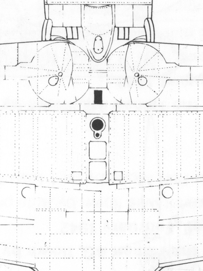
Oh, and I have a theory for why some sources say that the rectangular hole should be in the midline of the fuselage (see the attached graphic, taken from Sakaida's Osprey book), whereas others (like the Tamiya instructions) say that it should be in an asymmetric position, shifted to starboard.  Models A6M2, A6M3, A6M5 and A6M5a ("Ko") had two 7.7 mm machine guns on the hood.  In the A6M5b ("Otsu"), the starboard 7.7 mm machine gun was replaced by a 13.2 mm machine gun. For the A6M5c ("Hei"), a 13.2 mm machine gun was added to each wing, outboard of the 20 mm cannon. However, this made the traditionally ultra-nimble Zero fly like a truck.  Therefore, the left side hood 7.7 mm gun was deleted, and this became the definitive A6M5c.  So the A6M5c had only one gun on the hood, on the starboard side, while all the previous models had two guns side by side on the hood.

In the Zeros that had 2 guns on the hood, every component of the starboard gun would logically be somewhere to the right of the corresponding component of the port gun.  This would include the ejection chutes.  I think that in the 2-hood-gun Zeros, the ejection chutes converged near or at the end (as you also suspect), and expelled the shell casings through a rectangular exit hole centered on the midline of the fuselage.  But the A6M5c, with no hood gun on the port side, did not need a chute on that side.  Given the obsession with minimization of the Zero's weight, I think it's likely that the left gun's chute was removed, and that the left half of the rectangular hole was sealed.  That would leave the A6M5c with a single, asymmetric rectangular exit hole to the right of the midline, and probably half the size of the exit holes of the 2-hood-gun Zeros.  What do you think?
buitre

You can see two of my models here: https://www.youtube.com/watch?v=pdrzPW7cMls

  • Member since
    July 2004
  • From: Sonora Desert
Posted by stikpusher on Wednesday, March 1, 2023 2:45 PM

Cowl gun armament changed on the A6M5 series. On the 5A it was still the two 7.7mm machine guns. On the 5B, one of the 7.7's was replaced by a 13.2mm heavy machine gun. On the 5C, the remaining 7.7mm machine gun was deleted, leaving only the single 13.2mm HMG as a cowl gun. Obviously any ejection ports for spent brass and links will likely need to be enlarged for the 13.2mm gun compared to the 7.7mm guns.


F is for FIRE, That burns down the whole town!

U is for URANIUM... BOMBS!

N is for NO SURVIVORS...

       - Plankton

LSM


  • Member since
    December 2022
  • From: Canada
Posted by Tcoat on Wednesday, March 1, 2023 4:21 PM

buitre

Tcoat:

I agree that, for our purposes, it does not matter much if those hood guns feed from the left or from the right.  What seems clear is that they eject their shell casings downward to the rectangular hole immediately ahead of the forward main spar.

Oh, and I have a theory for why some sources say that the rectangular hole should be in the midline of the fuselage (see the attached graphic, taken from Sakaida's Osprey book), whereas others (like the Tamiya instructions) say that it should be in an asymmetric position, shifted to starboard.  Models A6M2, A6M3, A6M5 and A6M5a ("Ko") had two 7.7 mm machine guns on the hood.  In the A6M5b ("Otsu"), the starboard 7.7 mm machine gun was replaced by a 13.2 mm machine gun. For the A6M5c ("Hei"), a 13.2 mm machine gun was added to each wing, outboard of the 20 mm cannon. However, this made the traditionally ultra-nimble Zero fly like a truck.  Therefore, the left side hood 7.7 mm gun was deleted, and this became the definitive A6M5c.  So the A6M5c had only one gun on the hood, on the starboard side, while all the previous models had two guns side by side on the hood.

In the Zeros that had 2 guns on the hood, every component of the starboard gun would logically be somewhere to the right of the corresponding component of the port gun.  This would include the ejection chutes.  I think that in the 2-hood-gun Zeros, the ejection chutes converged near or at the end (as you also suspect), and expelled the shell casings through a rectangular exit hole centered on the midline of the fuselage.  But the A6M5c, with no hood gun on the port side, did not need a chute on that side.  Given the obsession with minimization of the Zero's weight, I think it's likely that the left gun's chute was removed, and that the left half of the rectangular hole was sealed.  That would leave the A6M5c with a single, asymmetric rectangular exit hole to the right of the midline, and probably half the size of the exit holes of the 2-hood-gun Zeros.  What do you think?


I think that the off center smaller port is for the two gun versions. in scale the hole just doesn't look big enough for the larger casings. All pictures I could find of it were two gun aircraft. The larger center line ones do look large enough though. There is also the distinct possibility that the lower rate of fire and only one gun allowed to to collect the brass instead of ejecting it. When the very late models came out resource conservation was vital since they had lost all their mines in China so collecting brass would be important. 


In the end I think we have managed to answer the question of if that hole had anything to do with drop tanks.


I love research!

  • Member since
    February 2023
  • From: Indiana
Posted by buitre on Wednesday, March 1, 2023 8:17 PM

Tcoat:

What leads you to think that the off-center smaller port is for the 2-gun versions?

From measurements that I have taken on the graphic from the Sakaida book, the rectangular hole would be about 144x84 mm in real life. We can also think of the hole as two144x42 mm side-by-side holes if we assume that the final hole that we see is the combination of two chutes, one coming from each gun.

I have looked up casing sizes in the web (https://en.wikipedia.org/wiki/7.7×58mm_Arisaka for the 7.7 mm casing, and https://en.wikipedia.org/wiki/13.2×99mm_Hotchkiss_Long for the 13.2 casing).  The dimensions (rounded off to the nearest mm) are 58 mm length and 12 mm maximum width for the 7.7 mm casing, and 99 mm length and 20 mm maximum width for the 13.2 mm casing.  I graphed out their sizes and the size of the hole (whole size and split-in-half size).  See below the relative sizes of the casings and of the two hole sizes.  (I am sure that there are other sizes of 7.7 mm and 13.2 mm casings, but I would not expect them to be too different from the ones I found.)

I am definitely no expert on this topic, but the casings seem to have pretty comfortable margins relative to the holes, even when we compare the larger casing (13.2 mm) with the half-size hole (shown in the lower right).


buitre

You can see two of my models here: https://www.youtube.com/watch?v=pdrzPW7cMls

  • Member since
    December 2002
  • From: Northern California
Posted by jeaton01 on Wednesday, March 1, 2023 11:47 PM

Here's a page from Tamiya's 1/32 Zero kit #60309, which shows the feed chutes from the two 7.7mm guns (it is an A6M5A, with the 7.7's in the fuselage and belt fed 20mm cannon in the wings. It does appear that both 7.7's feed to a common chute which is just in line with the rectanhular hole in the wing you all speak about.  This is an outstanding kit.  There's no help on the drop tank stuff, the kit has the fairing on the tank.


John

To see build logs for my models:  http://goldeneramodel.com/mymodels/mymodels.html


JOIN OUR COMMUNITY!

Our community is FREE to join. To participate you must either login or register for an account.

SEARCH FORUMS
FREE NEWSLETTER
By signing up you may also receive reader surveys and occasional special offers. We do not sell, rent or trade our email lists. View our Privacy Policy.