CyberHobby 1/35 Pz.Beob.Wg. IV Ausf. J - 12th SS "Hitlerjugend" - Dec. 1944 * Build Log *
Overview
The Panzerbeobachtungwagens IV Ausf. J is an Artillery Oberservation/Command tank that was assigned to Hummel 150mm self propelled Howitzer units. I'm building my Pz.Beob.Wg. IV Ausf. J as one that served with the 12th SS "Hitlerjugend" division during "Wacht am Rhein", December 1944. This variant of the Pz.Kpfw. IV Ausf. J features a StuG III G commanders cupola with 7 veiwports, observation periscope that can be raised and lowered, additional radio equipment and screen mesh side skirts.
I recently wrote an in-box review of the kit, which you can find here if you are interested:
CyberHobby 1/35 Pz.Beob.Wg. IV Ausf. J in-box review
Wheels, Drive Sprocket and Idlers
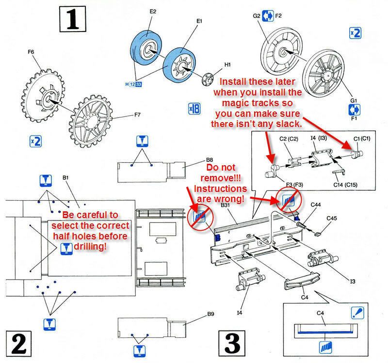
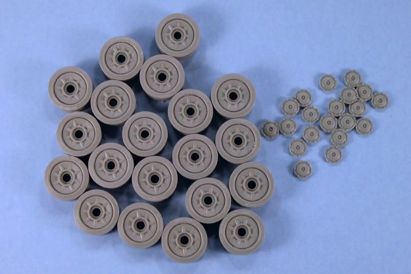
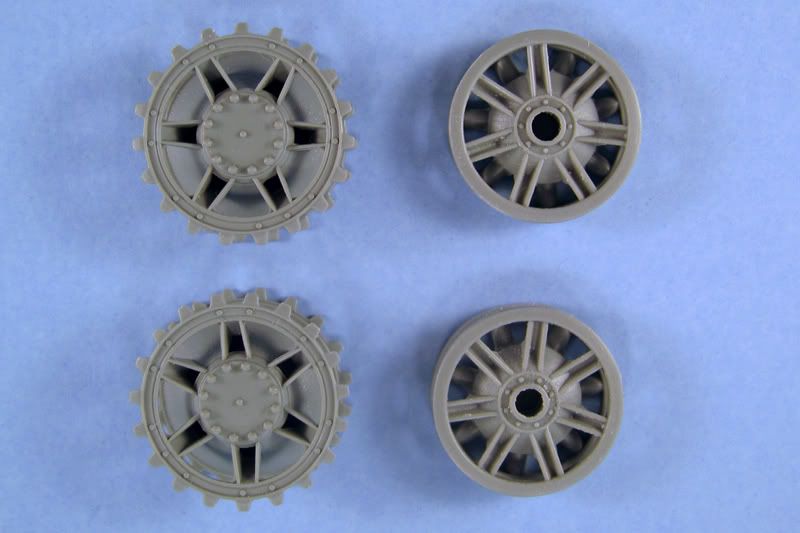
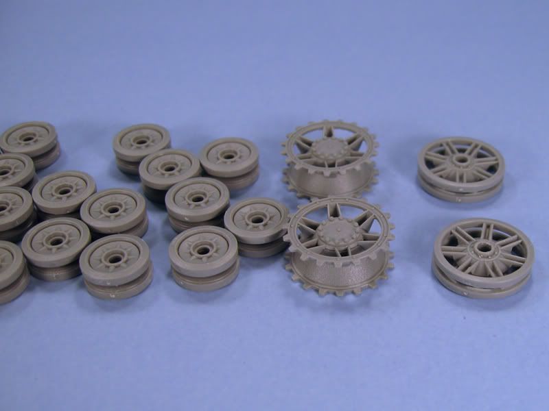
The road wheel assemblies consist of two wheels which are glued together in pairs with a separate cap that attaches to the center of the outer wheel. The front drive sprockets consist of two haves with a locating notch that ensures the teeth are lined up properly. There are two different idler sets provided in the kit, the early welded tubular style and the later cast variety. You will need to determine which is appropriate for the specific vehicle you're attempting to model. The cast idler is appropriate for my build. There is a positive locating notch which will help you get the spokes lined up however there is a far amount of slack. Be sure to line up the spokes so they are evenly between the spokes on the other half.
Each wheel and sprocket has three sprue attachment points that will need to be carefully sanded. A good set of sanding sticks helps immensely, so I use Flex-i-file Flex-Pad sanding sticks. Normally when doing road wheels, I keep the pairs separate until after painting. This time I decided to try something different and glued the pairs together first before sanding. I made sure the three sprue attachment points on each wheel lined up, then sanded around the outside of the wheels. This method helped to prevent accidental rounding of the rubber wheel edges as it's easier to keep the stick parallel to the surface of the two wheels.
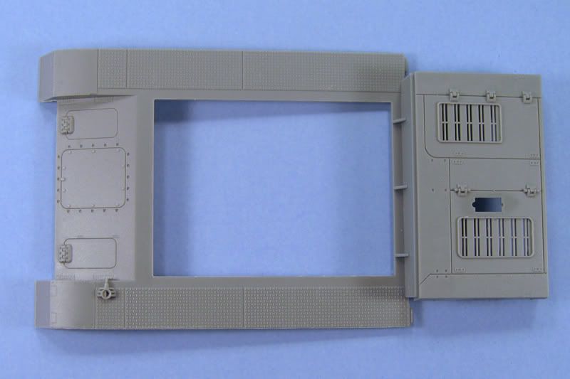
Upper hull, fenders and rear hull
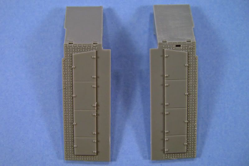
Next up are the upper hull, fenders and rear hull plate. The upper hull with the middle and front fenders attached requires six holes in the underside to be drilled through. Pay close attention to the instructions as some of the molded half holes are not to be drilled through and it can be a little confusing as the instructions are a little ambiguous. Each of the rear fenders will need to have two of the holes on the underside drilled through.
I got a couple of bigger drill bits for my pin vice that are just slightly smaller than the hole. I couldn't found my pin-vice anywhere so I figured what the heck, I'll use my cordless drill... worked like a champ! If you do this, keep the speed of the drill slow so the friction doesn't melt the plastic. Follow up with a round, tapered needle file to bore the hole out to the correct size for the locating pins on the tools and to clean up an excess plastic from the drilling.
There are a lot of ejector pin marks on the undersides of the fenders. They will be difficult to see so you could probably get away with not filling them if you choose. If you're planning on entering a contest with this build, then you'll want to fill all the visible ejector pin makrs which might be seen by a judge with a flashlight. Me being ze German zat I am filled them with a couple applications of Mr. Surfacer 1000. Once that was completely dry I sanded them down with the sanding sticks.
Lower Hull and running gear
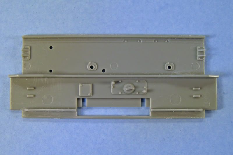
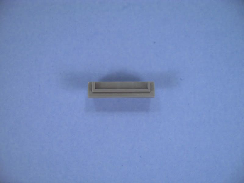
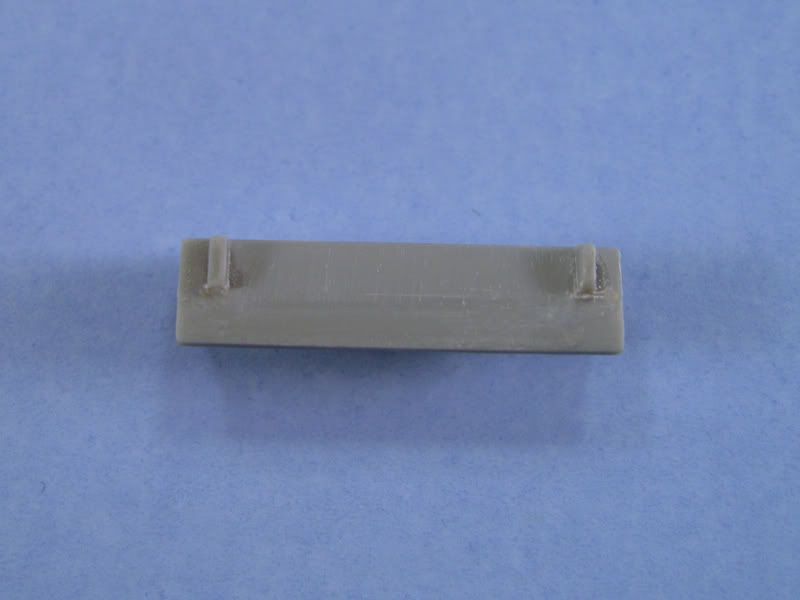
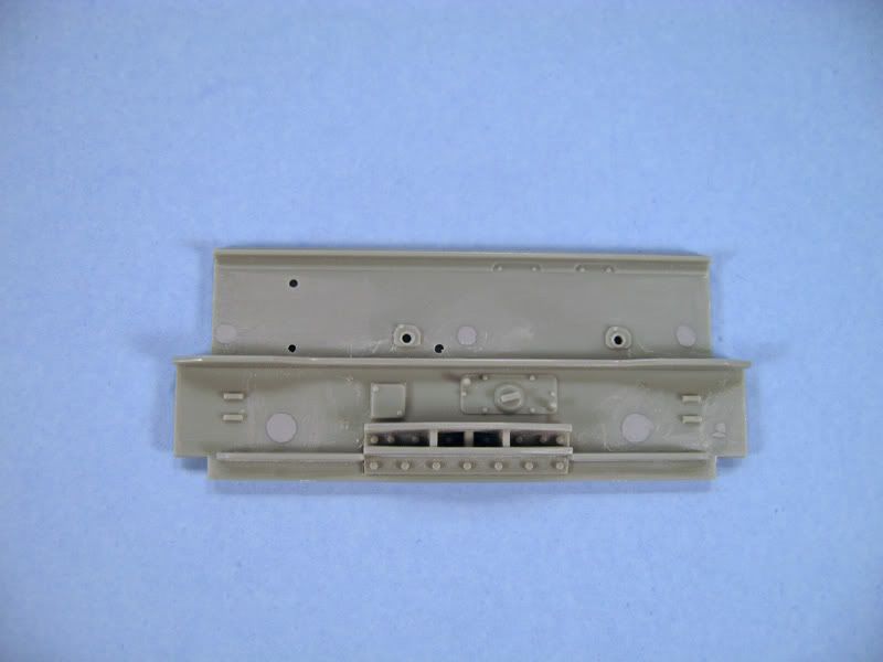
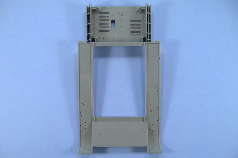
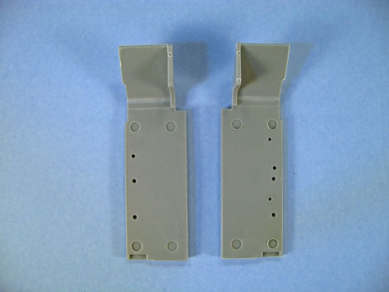
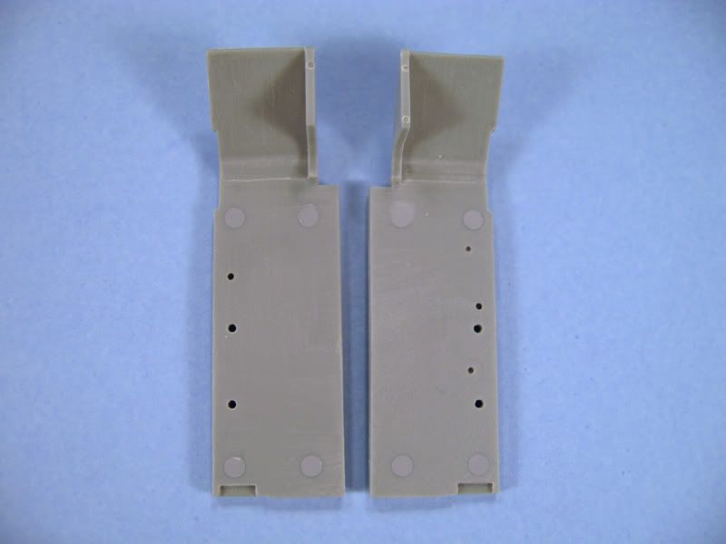
According to the directions you are to remove the two upper brackets on both sides of the rear hull plate.... DON'T DO IT!!! I blindly followed the instructions at this point, snipped them off and sanded them down only to discover that those should never have been removed! There are five ejector pin marks on the outside of the rear plate which were a little tricky. They were east to fill but a little difficult to sand down as there is not much room to get a sanding stick end in between the rest of the raised detail. If you're careful you can sometimes get away with gentle scraping with a chisel or angled chisel blade, just don't let it bite into the surrounding plastic or you'll have more filling to do. Part C4 needs to have the lower bar removed. I used an X-acto #11 cutting blade to cut into the two short vertical bars right where they met the long horizontal bar. This made it a little easier to carve the bar down. I then followed up with sanding sticks to smooth it all out. I completed the rear idler mounts/adjustments without attaching the idler axes parts F3 for the idlers. I will wait to attach those until after the assembly of the individual link Magic Tracks to ensure proper fit. Otherwise they might be off by up to one link and won't fit properly around the running gear.
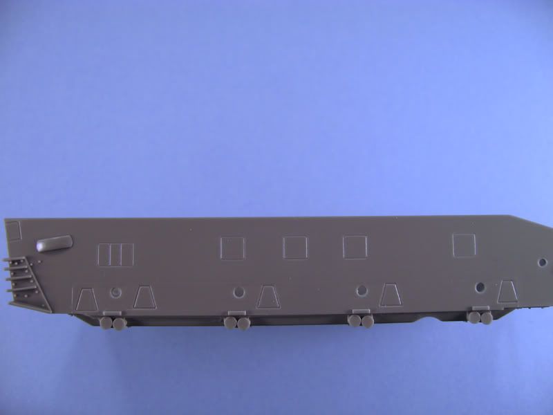
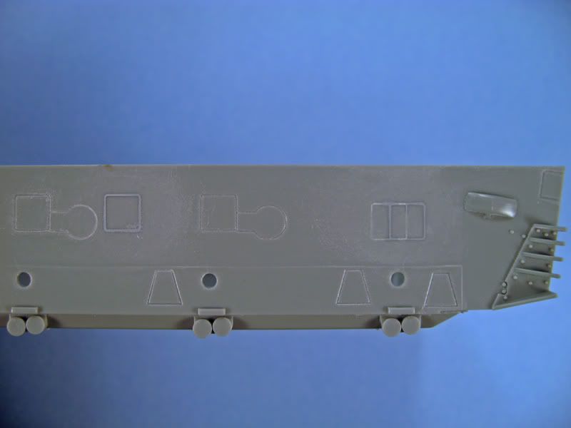
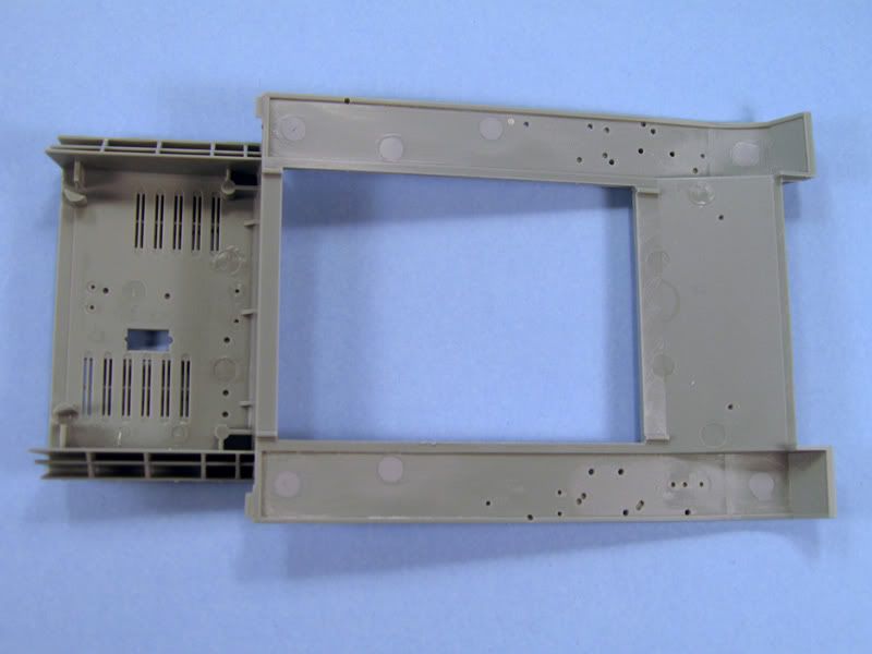
The hull tub has locating indentations molded into the sides so you'll get all the parts in the right place. Two of the locating spots on each side will need to be filled as they are for different variants of the Pz.Kpfw. IV. I used a couple applications of Mr. Surfacer 1000, then sanded them smooth once it was completely dry. The rear bogy locating squares have two boxes that overlap each other. Just fill the grooves for the rearward box, leaving the rest unfilled. You could even go one step further and fill them all in since you'll still be able to see where the parts go. The locating grooves are a little bit larger than some of the parts which some of you won't be too happy about.
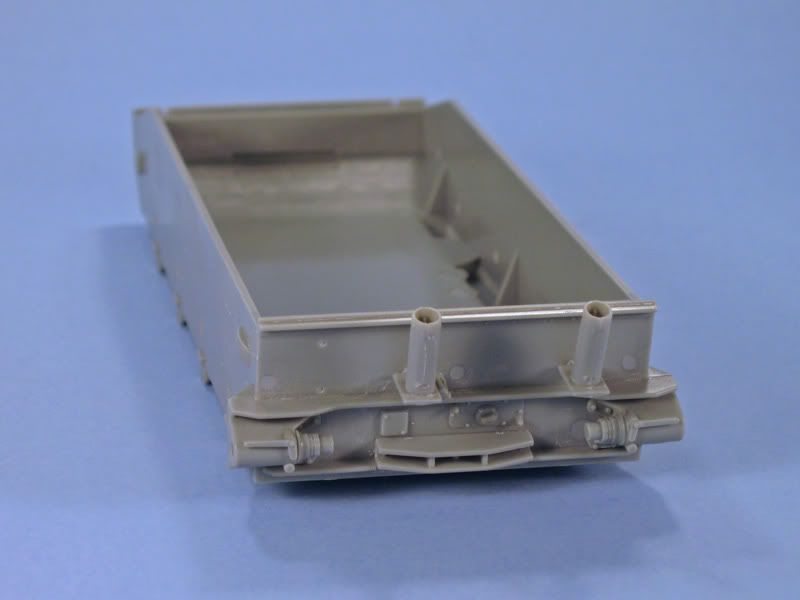
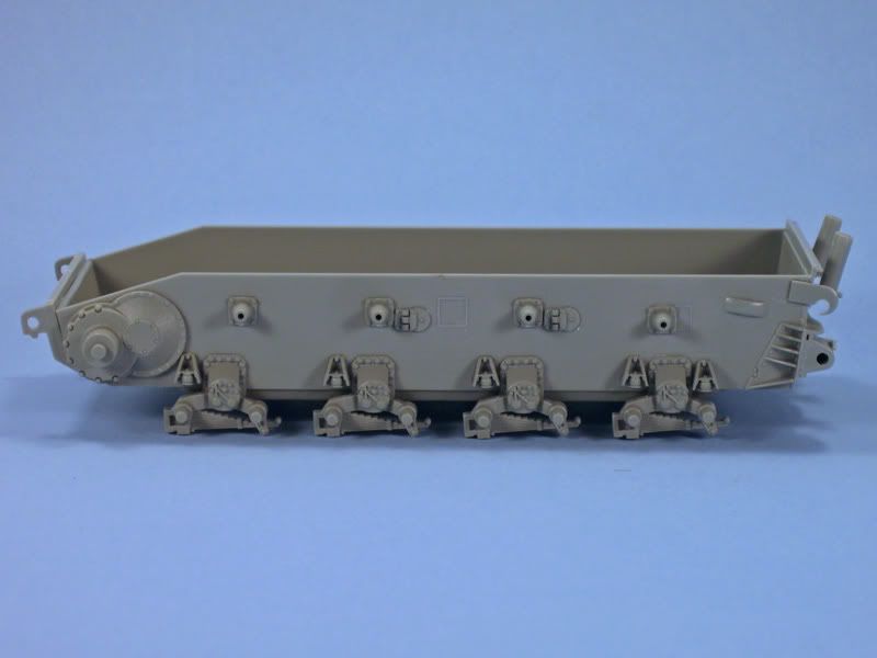
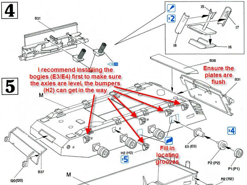
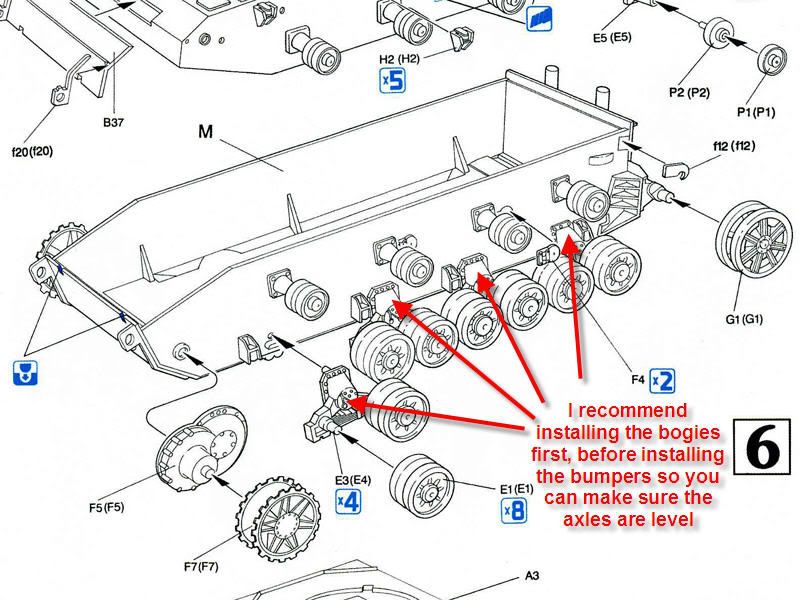
The front and rear hull plates fit without any problems. Just make sure the plates are square and flush with the hull tub, otherwise you'll have problems installing the rear tow hooks f12. I strongly recommend installing the bogies (E3/E4) before the bumpers (H2) as they can interfere with the mounting of the bogies and will make it impossible to get all the axles level.