Recreating geometry of a historical aircraft is usually a painstaking, iterative process. You can see this in my work on the SBD Dauntless. During the long hours of studying the photos and trying to figure out the precise shape of this plane I often wished to have its source blueprints! For many years the access to the original documentation was “the Holy Grail” of the advanced modelers. (Everybody wished to have this ultimate resource, but only few saw it. And even those, who saw these drawings, often did not know what they are seeing). For example - below you can see the original so-called "side profile" of the P-47:
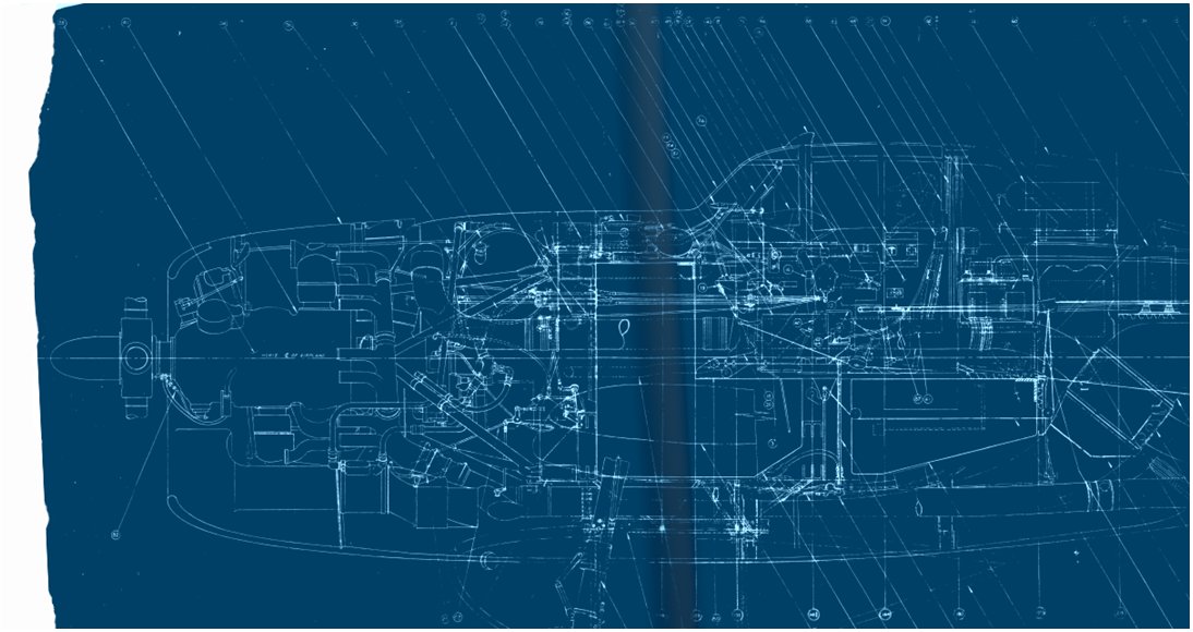
When the production of an aircraft is definitely closed, and it quits the service, its blueprints are packed into manufacturer’s archives. After a few decades most of these companies are sold, while the less successful ones are out of the business. The original technical documentation of an aircraft usually becomes a bunch of useless, unreadable paper rolls that disappear in trash bins.
Such a “total destruction” could occur, because in the “pre-computer” era there was just a single master drawing of each part, made (if there was enough time) in black ink on the tracing paper. (If there was not enough time, it could be even a pencil sketch). For the “everyday” use, the factory made cheap (and volatile!) workshop copies of these drawings, using the old blueprint or the newer diazoprint methods.
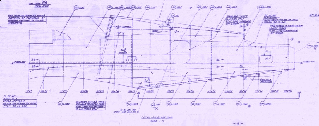
Both of these copying methods produced 1:1 duplicates of the original drawings. The older blueprint method was passing out in the 1930s, because it produced white lines on the Prussian Blue background (as in figure above). The diazoprint copies were preferred, because of their bluish lines on white (more-or-less) background (as in figure below):
Unfortunately, the contrast of the blueprints and diazoprints gradually faded after a few months of use (they are sensitive to light). Because of this factor, coupled with the usual wear and tear, the aircraft manufacturer had to continuously provide new replacements of the workshop drawings for the production and service purposes. In the WWII period they started to reproduce these drawings on microfilms. (This compact form was more economic and durable for delivering the technical documentation to all the service facilities, especially to those located overseas). Some of these microfilm rolls were later deposited in the national archives. This process was continued after the war, thus nowadays in the archives you can find microfilm rolls that contain documentation of various historical aircraft. However, this archival “environment” is better known to the professional historians than to the hobbyists modelers. (Historians know better, how to query a museum/library for the materials on a certain subject). Even if you manage to get the requested copies, there are also other questions: how to convert these microfilms into usable drawings? How to find among several thousand of drawings the one that you need?
Answering the first question: generally, there are special devices that scan the microfilm frame and store its digital image on the computer disk. You can buy such a low-end scanner, intended for scanning family slides (resolution: 3000dpi), in a computer store. It costs about one hundred dollars. The advanced microfilm scanners (of higher resolution: 4500dpi or more) are three to four times more expensive. (In the further text you will see why the resolution is so important). There are also companies which offer professional microfilm scanning services to various archives/libraries, as well as to the individuals.
To answer to the second question – how to use the technical documentation without going crazy (or lost) I need an example: scanned microfilm rolls. Fortunately, today you can find several Internet portals that offer the scanned microfilms of a few aircraft that are most popular among the aviation enthusiasts. Most of them are the WWII U.S. fighters, but you can find a few German (the FW-190, Bf-109, Me 262) and British planes (Avro Lancaster, Supermarine Spitfire, Sopwith Camel).
Ten years ago, there was a single site that offered these blueprints, and its prices were prohibitively high: as I remember, about one thousand dollars for a single aircraft. Fortunately, now they have competition, and the cost of a single set dropped to about one hundred dollars (depending on the site).
I will show you how I work with the original documentation of an aircraft on the example of the P-40. Scans of the blueprints that describe its later versions (P-40D..N) are widely available. This spring I decided to update my P-40B to the new Blender version (2.8), so I thought about buying a set of the P-40 blueprints, to improve the quality of this digital model. However, I did not expect that finally I will buy three different P-40 sets from three different portals! In this post I will describe, how it happened. In this way you will learn on my mistakes. In the next post I will describe how I organized these scanned images and used them for preparing the references for my model.
Initially I knew two blueprint portals: www.plans.aero and www.aircraft-manuals.com. Both of them offered about 7 thousand drawings of the P-40D..N. It seems that these blueprints were scanned from the same set of 8 microfilm rolls, labeled from “A” to “H”.
I started by ordering the cheaper set from aircraft-manuals.com: 68.85 USD + 7.85 USD of the shipping costs (they are located in Italy). After ten days I received a CD with these drawings. Technically they were monochromatic *.tif files, scanned at 2500dpi. (Size of each image: 3200x2368px). These files were organized into eight folders, which names corresponded the microfilm rolls (from A to H). The first frame of the microfilm contained the roll title page. You can find it in each of these folders under TIT~*.TIF name (for example – below you can see the TIT~2348.TIF file from folder E: )
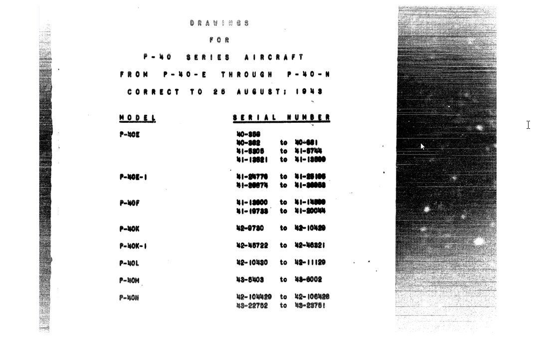
You can learn from this picture, that these drawings describe the state of the P-40 E, F, K, L, M, N documentation as on August 26th1943.
The easiest way to browse contents of these folders is enabling in your File Explorer the “Extra large icon” view option (as in figure below). All scan files (except the title) are named <N>_<o>.tif, where <N> is the original reference number (“punched” on each microfilm frame). The assembly blueprints, made on long paper rolls, can span over several subsequent microfilm frames. In such a case their frames share the same reference number <N>. However, their scans have different <o> suffixes. (It seems that the <o> is an ordinal number of the scanned file).
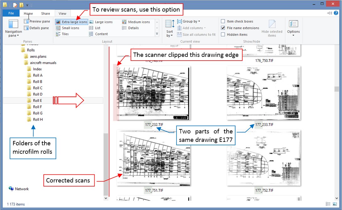
For example: on the roll “E” there were two subsequent frames marked as “E177”. They contained the wing skeleton assembly drawing, made on a non-standard format. However, there are four files named 177_*.TIF in the folder E (see figure above). It seems that the person who made these scans, first created the 177_232.TIF and 177_233.TIF files. I suppose that later somebody reviewed these scans and found that the left edge of the wing in file 177_232.TIF was clipped. Thus, they made two additional scans of these frames. These corrected pictures are named 177_751.TIF and 177_752.TIF (However, I do not understand why they did not remove the first, spoiled pair of files. Maybe because in 177_752.TIF some lines fade into the background?).
My basic idea of organizing these drawings into something usable for the further work was a tree-like folder structure. On the first level I created folders for the basic assemblies: Fuselage, Wing, Empennage. Then in each of these folders I created directories for their subassemblies. For example, in the Fuselage folder I created the Spinner, Engine Cowling, Cockpit and Tail Wheel directories. Then I was going to review and move the scans from the source (Roll A… H) folders into this newly created structure. I thought that I rename each moved file, giving it a descriptive name (like “General Assembly”, “Skeleton”, “Bulkhead at STA#1”, and similar). In each of these target folders and subfolders there should be no more than 100 drawings. (Eventually I can also create additional subdirectories, when needed). Of course, I will skip all the unnecessary drawings of small inner details, focusing mainly on the assemblies.
However, there was a drawing identification issue. Recognizing the main assemblies, like the one below, was easy:
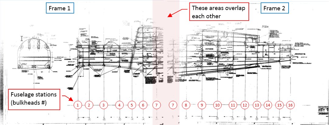
But when it comes to the subassemblies, you often cannot identify the depicted part at the first glance. For example, look at the drawing from frame E261:
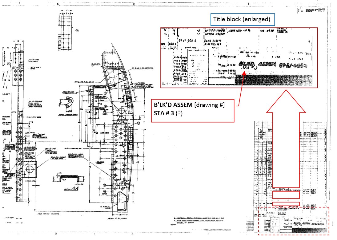
I could not identify this part just by its shape. So I looked at its description (they are always placed in the lower left corner). There was an unpleasant surprise: the original drawing was so large that its title block is nearly unreadable. (The scanner resolution was too low!).
Fortunately, aircraft-manuals.com also provided scans of the index pages that originally accompanied these rolls:
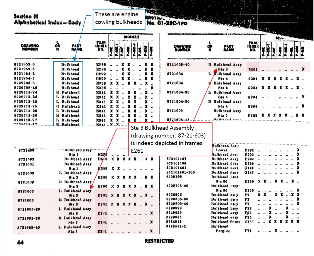
It was intended for searching by the drawing number or part name. I did not know the drawing number (last digits in the title block are unreadable). The name index is divided into seven main sections: “Wing”, “Tail”, “Body” (i.e. fuselage), “Power Plant”, “Flight Control”, “Equipment”, “Armament”. I was afraid that searching this index is not especially practical, since the part names are not unique: the first four pages of the “Wing” section list items simply named “Angle”. Fortunately, in the “Body” section you can find also the bulkhead station numbers. Using them I finally confirmed that the first word “B’LK’D” is a Curtiss shortcut for “BULKHEAD”, and that this E261 frame contains the STA#3 bulkhead assembly. (From the index entry I could read its drawing number: 87-21-603). Note that even in this index some frame references in the “FILM INDEX NO.” column are unreadable, because of the low image resolution!
When I started to study details of the identified drawings, the low resolution of the assembly images became a serious issue. The references to the detailed drawings were unreadable, as well as many key dimensions. For example – look at this middle part of the fillet between the wing and fuselage (E201), depicted in the blueprint below:
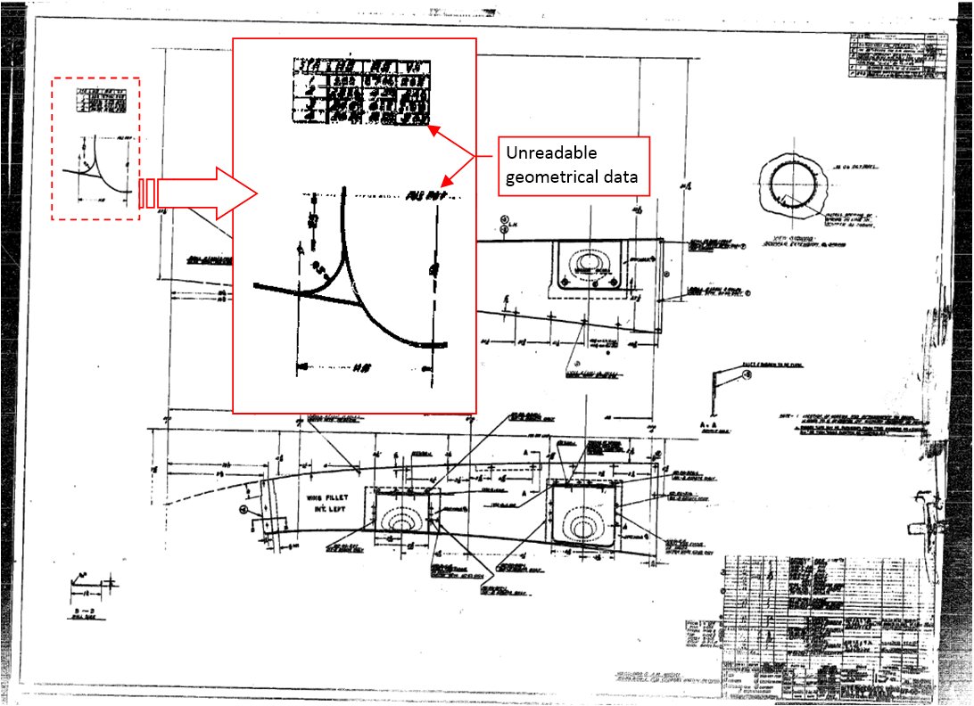
In this case the title block was completely unreadable, so I had to confirm its identity searching the fuselage name index for the “Fillet” term. In this way I identified the number of this drawing: 87-06-503. Strangely enough, in this index you can find the next segment of this fillet (drawing number 87-06-502, E200) several pages later, under name “Skin”. The geometric data that describe shapes of these fillets are placed in the upper left corner of their drawings. As you can see in figure above, they are completely unreadable.
The poor image quality of these scans is not only caused by the inadequate resolution. They also lack shades of gray, which could improve a little bit the overall readability. (They are high-contrast black-and-white images, without any halftones).
At this moment I realized that scans from aircraft-manuals.com are of little use for me, and started looking for better ones. Thus, I read again the description of the P-40 package offered by the other portal: plans.aero. They claim that “Roll E has now been completely re-mastered at super high resolution because the original records were overexposed.. We have scanned Roll E @ 4,500ppi and darkened the scans to bring up all detail in the film”. Now I understood what they are saying! (Roll E contains most of the assembly drawings, so this is the “critical resource” of this microfilm set).
Thus, I bought my second P-40 documentation set from plans.aero. It costed 119 USD, and there were no shipment fees, because you can immediately download these files. The total size of this set is about 6GB (ten times more than the set from aircraft-manuals.com). For the user convenience it is split into four parts for separate downloads. For the higher price than aero-manuals.com, plans.aero provide not only the scanned rolls, but also all the available P-40 manuals, in particular the P-40N “Erection and Maintenance” and illustrated “Parts Catalogue”. (These books are a useful addition, and they would cost much more when purchased separately).
The scanned files are grouped into the “roll folders”, as in the set from aircraft-manuals.com. It seems than plans.aero provided the gray-scale pictures for rolls A and F (that’s why in some of them you can see white lines on a black background). There are also two folders for roll E. One of them, titled “old scanning” contains the same pictures that I got from aircraft-manuals. The another, titled “new scanning”, contains PDF files. Each of these PDF is a scanned film frame:
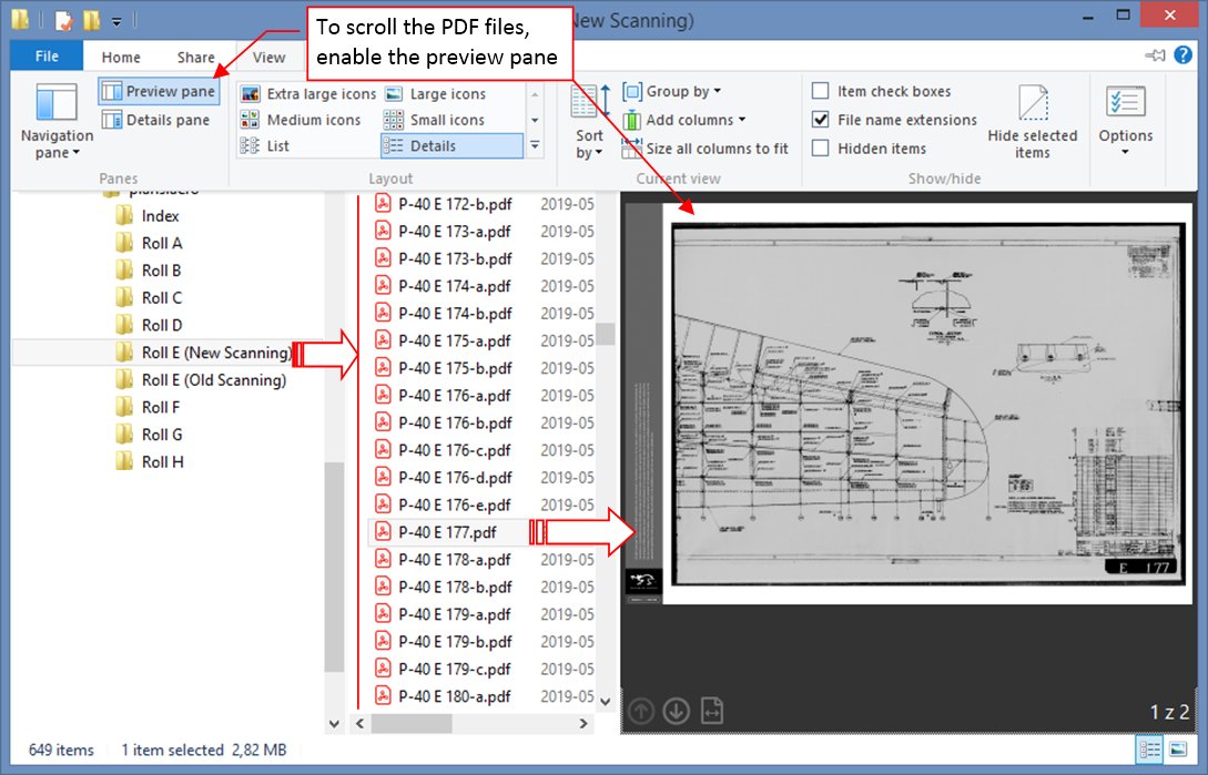
As you can see on the picture, all the PDF files have a “P-40” prefix, followed by the full microfilm reference number (with the roll letter prefix: “E”). For the drawings that span over multiple frames, the sequential suffix is used (“-a”,”-b”, “-c”, and so on). Using this rule, I assumed that there should be two files: “P-40 E 177-a.pdf” and “P-40 E 177-b.pdf” for the wing skeleton drawing (E177). To my surprise there is only one, named “P-40 E 177.pdf”. It contains the right side of this drawing. Where is the left side? I quickly found that you can find it in file “P-40 176-e.pdf”. (An evident mistake of the scanner operator, but once identified, you can easily correct it by renaming these two files).
Of course, the first thing that I have checked in these new files was the table with the geometry data in the upper left corners of drawings E200 and E201:
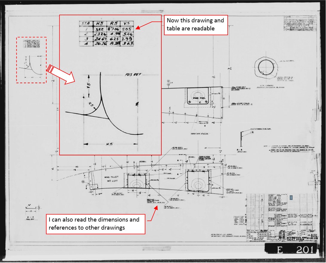
It was definitely better: now I was able to read this simple diagram, the fillet ordinates table, as well as all other dimensions and drawing references.
I could close this blog post here, concluding that the www.plans.aero offered better blueprints of the P-40 (and additional manuals). However, when I described this case to my friend, he suggested me to visit yet another site: www.aircorpslibrary.com:

AirCorps Library portal was set up in 2015. For 5 USD per month (or 50 USD per year) it provides online access to the original documentation of various aircraft, including manuals and drawings. At this moment you can find there documentation of 29 aircraft (all of them are U.S. designs from WWII-era, with a single exception: the Spitfire). Among them is the “P-40 Warhawk” section:
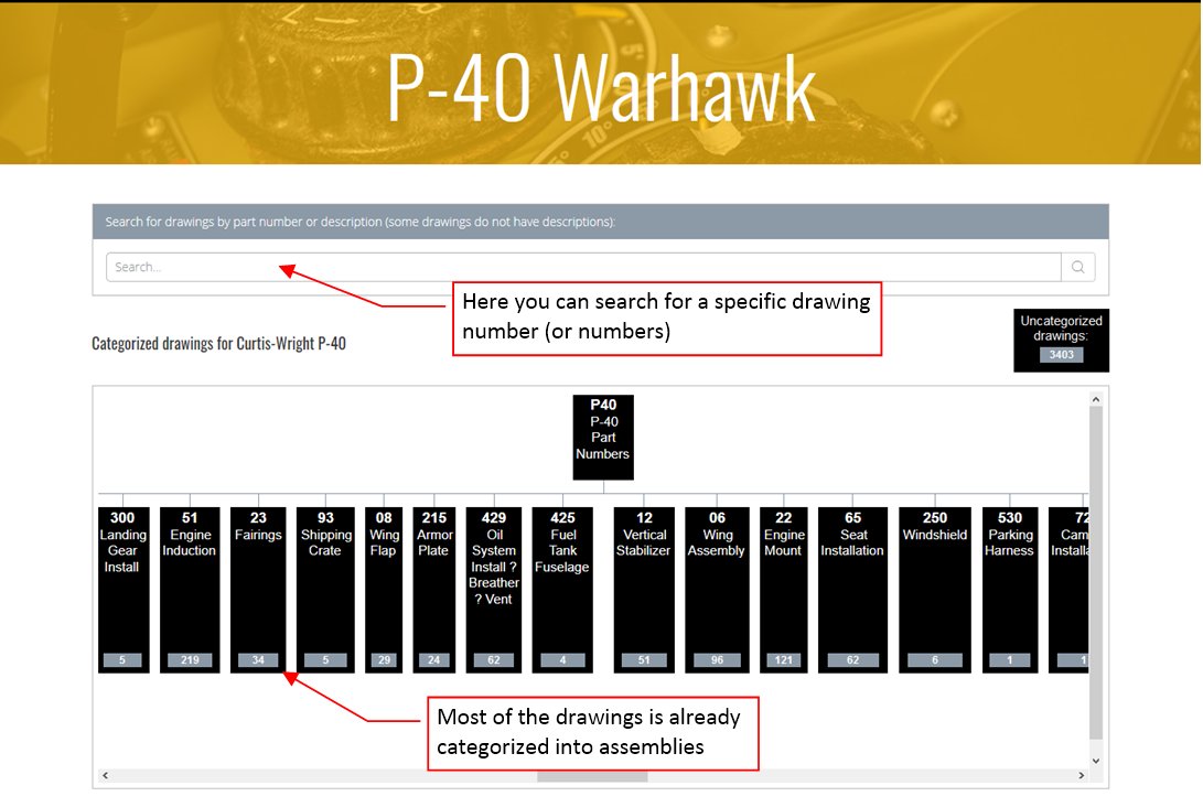
Instead of the indirect “roll index numbers” this site uses the original drawing numbers from the drawing title blocks. (I suppose that they used an OCR process to “extract” them from the scans). Using the drawing numbering rules specific to the manufacturer of each aircraft, AirCirps Library automatically splits the scanned drawings into subassemblies. For example: it seems that in Curtiss the drawing number was built of 7 digits divided into three sections: TT-AA-NNN. The “TT” was two-digit type designation. In particular, the “75” prefix is for the “Hawk 75” (i.e. P-36), while “81” is for the YP-37, and “87” is for the “Hawk 87” (P-40D and later versions). (Frankly speaking, I would expect that “81” stands for the “long nose Hawks”, i.e. early P-40 versions, designated by Curtiss as “Hawk 81”. However, this is not the case). The “AA” (after 1942 also three digit: “AAA”) section indicates the subassembly, for example: “03” – Wing components, “05” – Aileron, “06” – Wing Assembly, “08” – Wing Flap, “21” – Fuselage, “23” – Fairings, and so on. (The diagram of the P-40 components is based on these two or three middle digits of the drawing number). Finally, the NNN segment seems to be a kind of an ordinal number. The assembly drawings usually have one or two leading zeros in this last segment (for example: “001”, or “010”). Thus, in this graph you can find the fillet between the fuselage and wings in the group “06 – Wing Assembly”, because their drawing numbers are 87-06-502 and 87-06-503. (I just do not know why in the microfilm index these parts are assigned to the “Body” section – i.e. fuselage – instead of the “Wing” section). In this “analog era” you could encounter a trace of human error everywhere: thus, in the “06” section you can also find an forgotten P-36 “Markings & Insignia Airplane” drawing (75-06-013).
I am not sure, but it seems that different aircraft versions (for example – the P-36 and the P-36C) can be recognized by the fifth digit of their drawing numbers. For example: the basic wing design is described by drawings numbered from “75-03-001” .. to “75-03-3XX”. The P-36C had different leading-edge section, which is documented by “75-03-4XX” drawings. Similar, you can find the two-gun wing assembly of the export Hawks 75 in the “75-03-6XX” drawing series).
Note that I have just mentioned another aircraft: the P-36. This is not a mistake: this “P-40” section of the AirCorps Library contains 11 thousand blueprints of at least three (!) different (although related) aircraft types:
- P-36 (internal Curtiss name: “Hawk 75”, drawing prefix: “75-*”);
- YP-37 (drawing prefix: “81-*”);
- P-40 cu/B/C (the “long nose Hawks” - internal Curtiss name: “Hawk 81”)
- P-40D…N (the “short nose Hawks” - internal Curtiss name: ”Hawk 87”, drawing prefix: “87-*”)
Depending how you count p. 3 and p. 4, there are three or four aircraft. It seems that Curtiss prepared the P-40 project “in a hurry”, because there are just a few XP-40/P-40cu drawings, most of them of poor quality. (Their light lines fade into the background – as if they were originally made in pencil instead of the tracing paper and ink). Strangely enough, all these early P-40 drawings have “75-*” suffix and “8” as the fifth digit: “75-XX-8XX” (as if this aircraft was another version of the P-36). Could it happen that it inherited the “Hawk 81” name (used internally by Curtiss) after the unsuccessful YP-37 project?
When you click one of the assembly graph items or type a mask expression in the search box (for example an expression like: “75-*-8*”), you will obtain the blueprint result list similar to the picture below:
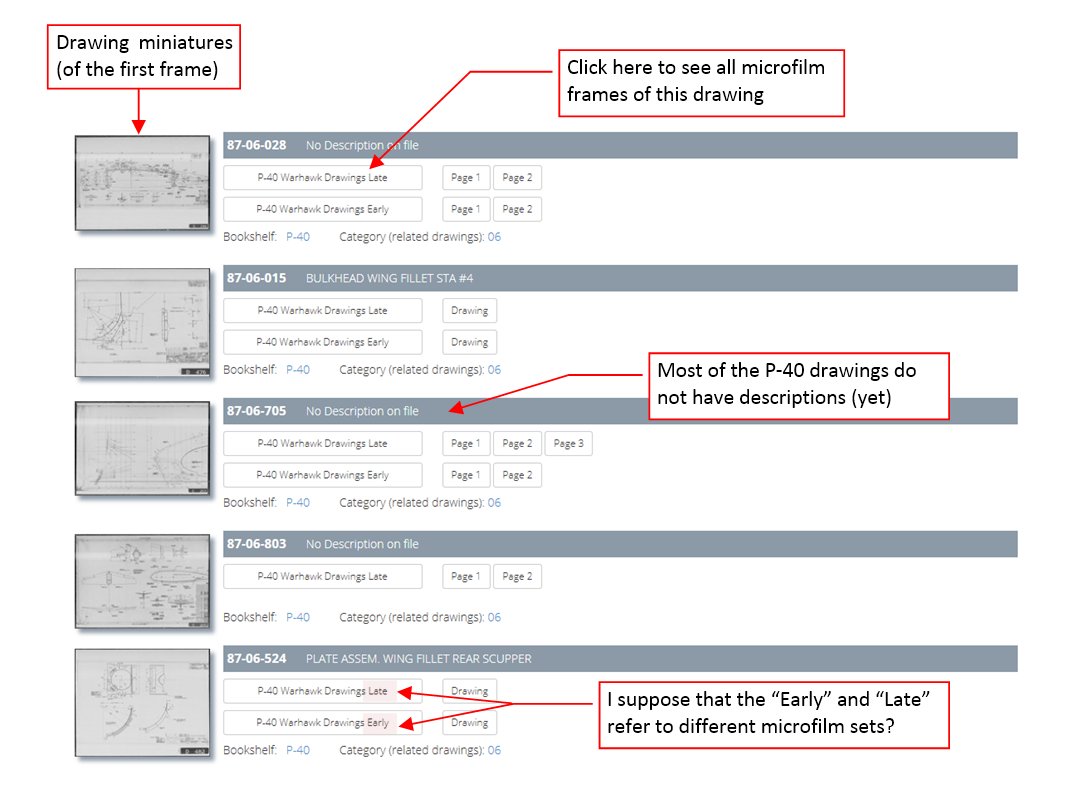
In other aircraft sections (for example – the P-51) you can also search by drawing name. However, most of the P-40 drawings have no description, yet. When you click the drawing miniature on the left or one of its buttons on the right, you will open this blueprint in the drawing viewer. Figure below shows how it looks like:
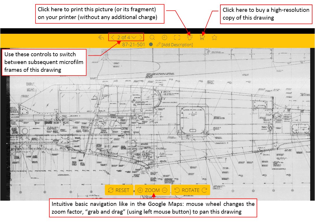
The online viewer is quick and intuitive. It allows you to switch between subsequent microfilm frames. It also provides the pull-down menu where you can see their miniatures. You can easily zoom and pan across the image using the mouse (in the same way as you do it in the Google Maps). The portal dynamically adjusts resolution of the displayed image to the current zoom settings.
For me, the most important feature is the possibility to print this drawing locally, in a decent resolution, without any additional charges. Below you can see how such a printout looks like:
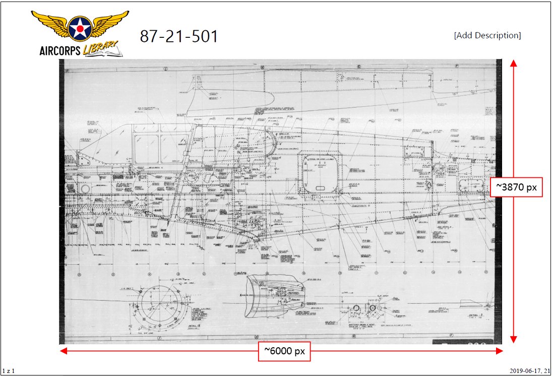
The paper size of your printout does not matter – it can be A4 or A3, it does not have any influence on the picture details. This portal simply sends to your printer a raster, grayscale picture which is about 6000px wide and 3870px high. For my purposes I need these pictures in an electronic form, thus I used a popular print capture utility to convert them “on the fly” into PDFs.
When I visited AirCorps Library site for the first time (at the beginning of June 2019), there was a single purchase option: a full-scale printout, which was not especially interesting for me. When I am writing this post (two months later), they introduced some modifications. Now you can buy and download copies of the manuals and drawings that they expose online. Thus, when you click the “Purchase” icon in the drawing viewer, you will see two options: “Purchase Hi-Res” and “Download”. Selecting the “Purchase Hi-Res” option you can order a paper printout (on a 24”, 36”, or 42” sheet). The new “Download” option allows you to buy the image you are viewing (size of the downloaded image: 9888 x 6984px). However, this means that in the case of multi-part assembly drawings you have to buy each microfilm frame separately. As long as the high-res printouts are available, I am not interested in the downloading option. (I have just bought a single picture, and concluded that the local printout resolution is enough for my purposes).
Below I compared the test images (this is the fillet ordinates scheme and table from the upper-left corner of drawing 87-06-503). I obtained these pictures from the aircraft-manuals, plans.aero (“new scanning” PDF), and AirCorps Library (using the local printout function):
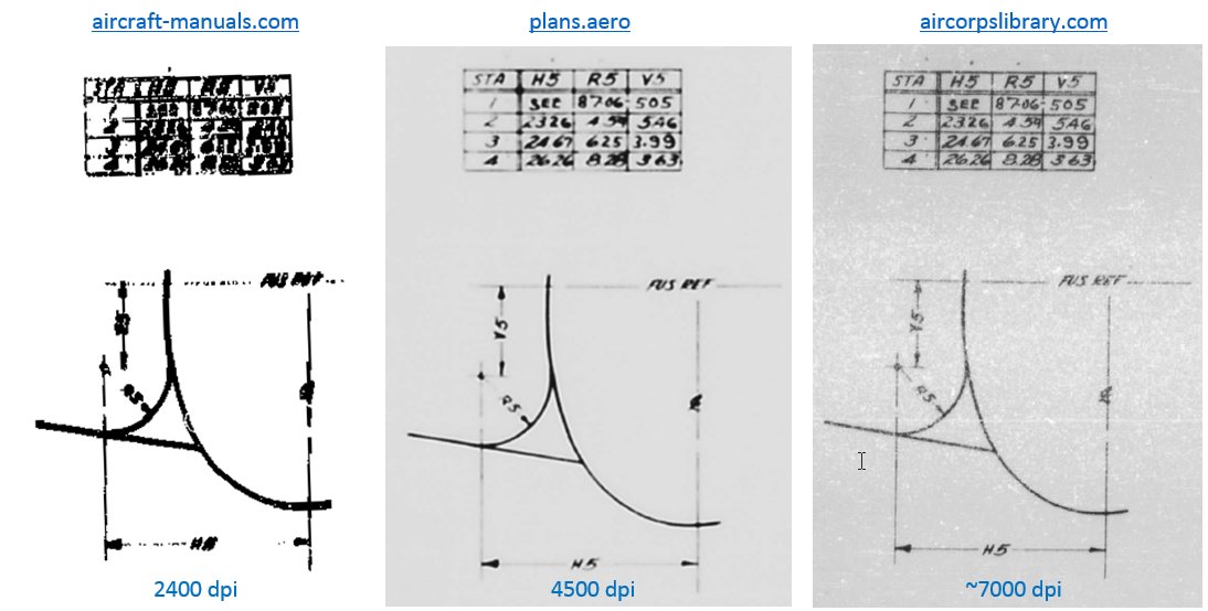
As you can see, the best images are from AirCorps Library. I suppose that they scanned the Curtiss microfilm at 7000 dpi, and the original size of each scanned frame is as in the purchased image: about 10000 x 7000px. For the local printouts this image is scaled down to 6000x3860px, but this operation only slightly degrades its quality. (The image on the right is the local printout fragment).
Conclusion: if your are looking for the blueprints of one of the U.S. aircraft (or the Spitfire) – start by buying a monthly subscription of the AirCorps Library online resources. Even if they remove the local printing function (this portal still evolves!) you can use it to learn what the preserved microfilms contain. A complete package of the blueprints and manuals you can buy from plans.aero – and eventually use the AirCorps Library to check some details in the higher resolution.
Note that the collections of AirCorps Library and plans.aero are not identical. The plans.aero portal offers only the most popular U.S. fighters: F4U-1, P-40, F4F, F6F, P-51, P-47, and a single bomber: TBF-1. However, you can also find there the blueprints of some foreign aircraft that are not present in the AirCorps Library: Bf-109, FW-190, Me 262, Avro Lancaster, Sopwith Camel and Pup.
Finally, if a certain aircraft is available only in aircraft-manuals.com – you can use this portal, but first try to ask for a sample of a large assembly drawing from the package you need. (I do not know if they will answer, but at least it is worth to try such a check before purchasing). Maybe they scanned the microfilms of other aircraft using better resolution? You can also use as an “ad-hoc” indicator the number of DVDs they offer in the set divided by the number of scanned drawings it contains. The lower value of this ratio, the better.
In the next post I will describe how I use these original P-40 blueprints, preparing the reference drawings for my model. (In this way I will try to answer the second question from this post: “how to use the technical documentation without going crazy”).