SEARCH FINESCALE.COM

Enter keywords or a search phrase below:

US Navy 5"38 Mark 28 Twin Turret in 1/35 Scale with Full Cutaway down to the Magazines

9873 views
62 replies
1 rating 2 rating 3 rating 4 rating 5 rating
  • Member since
    April 2003
  • From: USA
Posted by keavdog on Wednesday, January 10, 2024 10:13 AM

Will follow on kitmaker!

Thanks,

John

  • Member since
    March 2012
  • From: Louisville, KY
Posted by Builder 2010 on Wednesday, January 10, 2024 10:04 AM

Please do! I post on those three sites after every session and I can click and drag every picture directly from my files. They also don't chug along and have the latency problem. Even my file sharing site changed their policy and now changes the file names to some temp file identifier, making it harder for me to ensure that I'm not downloading doubles.

  • Member since
    May 2009
  • From: Poland
Posted by Pawel on Friday, January 5, 2024 8:55 PM

Hello Builder!

It sure is sad to hear you say that - but then it's also understandable... They've been kinda asking for it, haven't they? That thing with the pictures, while saving some money has been driving so many people away for years. And now the access problems, too...

Anyway, good luck with your project and I hope to see you again, somewhere else!

Paweł

All comments and critique welcomed. Thanks for your honest opinions!

www.vietnam.net.pl

  • Member since
    March 2012
  • From: Louisville, KY
Posted by Builder 2010 on Friday, January 5, 2024 6:12 PM

Just lost part of the post... I really don't like this website and I'm giving up on it and directing all my readers to one of the others to which I contribute the same thread. You have several choices: 

https://forums.sketchup.com/t/5-38-twin-turret-cutaway/237281/21

Or

https://forums.kitmaker.net/t/5-38-cutaway-turret-complex-cad-and-3d-printed/31783/80

or

https://ww2aircraft.net/forum/threads/5-38-mark-28-twin-gun-secondary-battery-from-iowa-class-battleships.61661/page-6

While I'm a big fan of Fine Scale Modeler, the Forum web engine is one of the worst I've seen. I don't like having to double handle all of the hundreds of images I create. I don't like the intrusive ads that hog the screen space (especially the constant animation that distracts your vision, and I don't like that halfway through a post, the response time starts slowing down so I'm typing with nothing going on the screen until it finally catches up. I'm sort of a touch typist, but need the visual feedback to do it right.

All of these other sites enable you to drag and paste pictures directly from my downloads file folder into the thread with no additional handling.

And one last thing, 

I also don't like "No spell check". It's like working on the Internet in 2005.

Of the three sites listed, the first, is the SketchUp forum. I'm posting there since this project and the 16" project that preceded it, are so heavily driven by SketchUp design that it made sense to put it there. There are experts there (even beyond my skills) that have gotten me out of jams.

The second is the Kit Maker forum, a massively comprehensive modeling community that gets a lot of response.

Lastly, is the World War 2 aircraft site. It's the most international with folks from all over world. While I'm not doing a WW2 aircraft, I'm doing a WW2 naval gun system and they like it. They contribute a lot of commentary which I really like.

So please, put me out of my misery and check them out if you wish to follow every day's adventure.

  • Member since
    March 2012
  • From: Louisville, KY
Posted by Builder 2010 on Saturday, December 30, 2023 10:24 AM

The wall print was very good. I broke some of the door dog levers, but that's expected. They're very delicate and I will replace with wire. The walls fit together as designed.

I put together a punch list for the upper works and it has 19 items on it. So there's still a lot of work to be done here before turning my attention to the lower decks and main magazine. I almost have all the reference photos I need to finish this. I have just a couple more requrests for Ryan concerning the communications gear on the gun house rear wall, and the geometry of the cartridge chutes.

The sight setter's seat came out better than expected. The support post is delicate, but the new 3.1 second printer settings are producing small details that have some strength. I post-cured these last two batches BEFORE cutting off the supports to impart more strength to withstand the support removal. It worked well.

This little bit of floor has to key into the flanking gun mounts. I needed to find out if I could install it after the sighting system part was installed. Luckily, it could be.

This was the test.

I now had another decision facing me. Do I paint the sight system before installation or after. I put it together now. It required a lot of pushing and shoving to get it all aligned during the tests, and I even broke one of the cross-rods. This led me to believe that I would really mess up the paint job in the process. I bit the bullet and permanently glued it in now and will wrestle with the painting going forward. What I can't reach with paint won't be visible anyway—or so I'm assuming.

For some reason—probably some warpage—the trainer's regulator console didn't sit down on the frame. Rather than continue to forve it, I made a shim. Again, no one will notice this when painted and enclosed in the gun shield.

Right now I'm about designing the cartridge chutes. I have good orthographic line drawings, but they don't show the contours. I don't believe these sheet metal contrivances are rectangular in cross-section. I'll do the best I can, and then, after New Years ask Ryan for some pictures of its true shape.

This is that punch list to which I referred:

Everyone have a safe and happy New Year and I'll see all y'all in 2024!

  • Member since
    March 2012
  • From: Louisville, KY
Posted by Builder 2010 on Thursday, December 28, 2023 5:29 PM

Things are quiet on the homefront. Due to the nature of my wife's cancer, even though the pathology was clear, will undergo a short cycle of Chemotherapy. All of this will be over in mid-March and we'll be happy when it's done.

During her recovery I didn't work in the shop much, but I did a ton of drawing and got a lot of printing done. This is an example of one load with lots of odds and ends for gun house details. This pile includes shaped junction pieces to help me glue the roof plates at the correct angles and those really neat "tractor seats" for the trainer and pointer positions. I had found a bar stool with the correctly shaped seat on the SketchUp 3D Warehouse and then modified it to print and conform to the ship's seat size and shape.

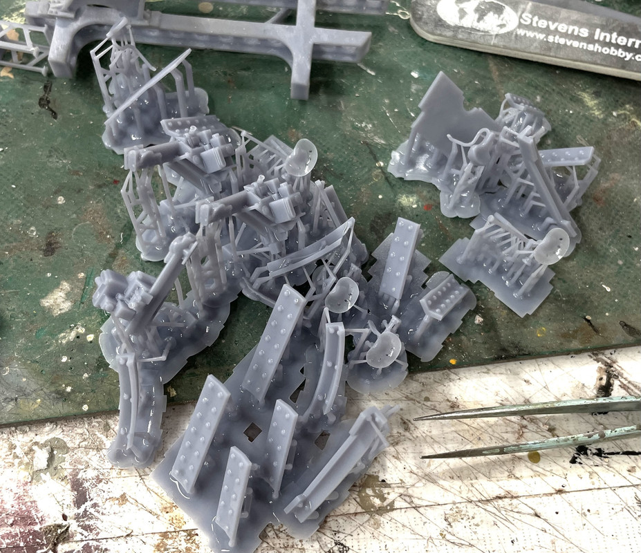
Here's a closer look at the seats. There's one more that's printing now. It's the bicycle-shaped seat for the sight setter position. It's in the pile above, but, the bottom mounting flange was a separately grouped drawing that I neglected to combine with the overall model. When I conveted to the STL and then the printer, that flange wasn't there so the seat pole was just dangling in open space.

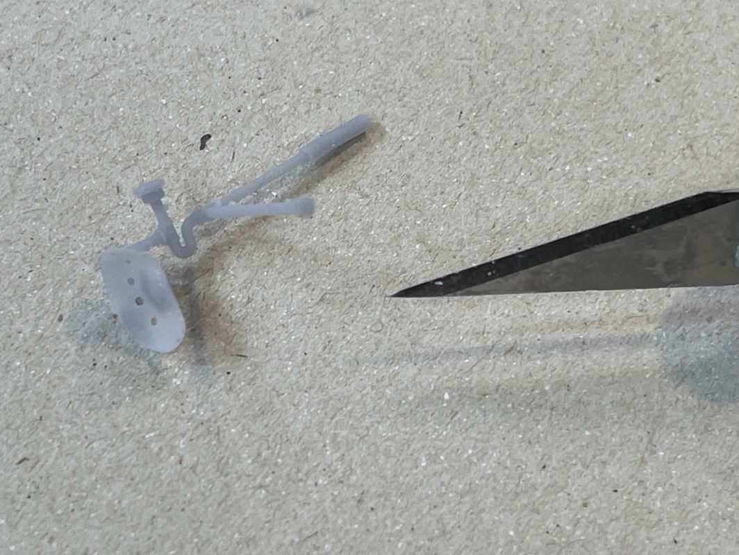
This is the pointer seat:

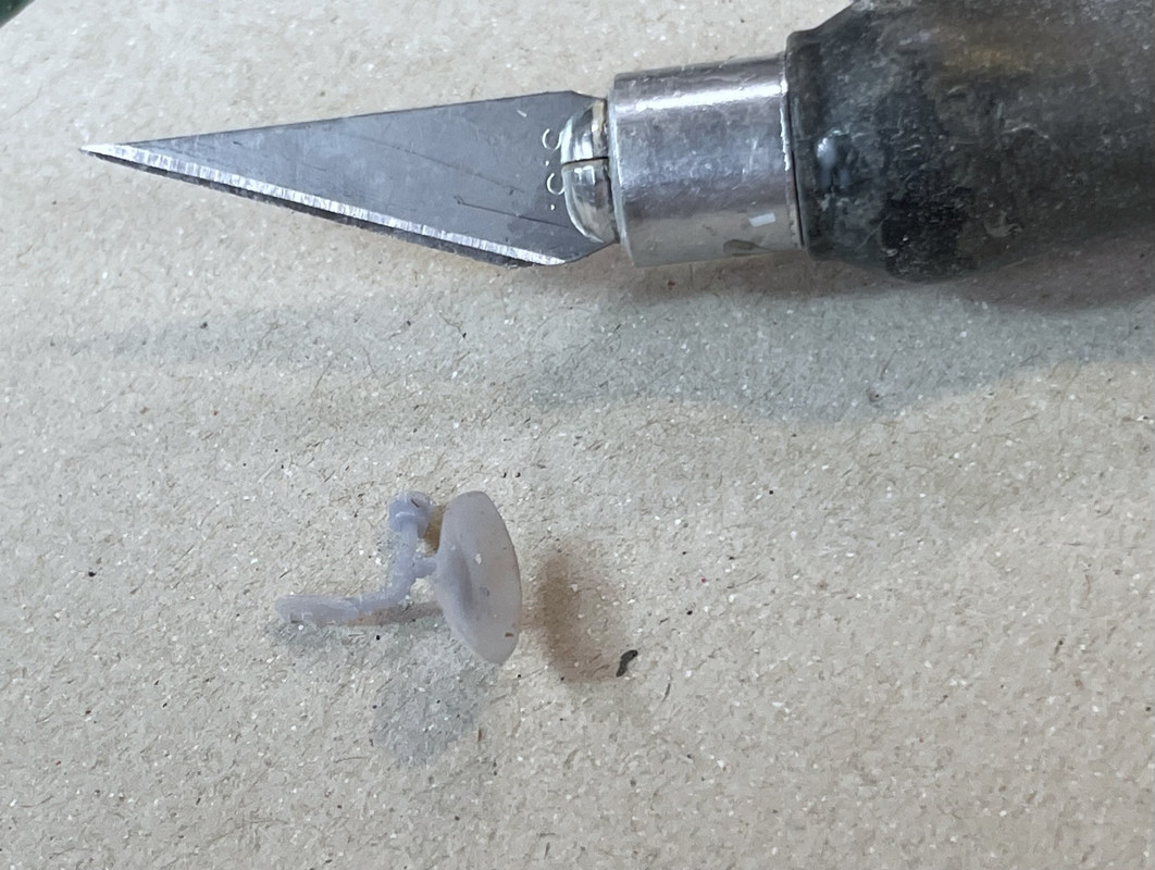
And this is trainer seat. Both are REALLY delicate, but well cured and formed.

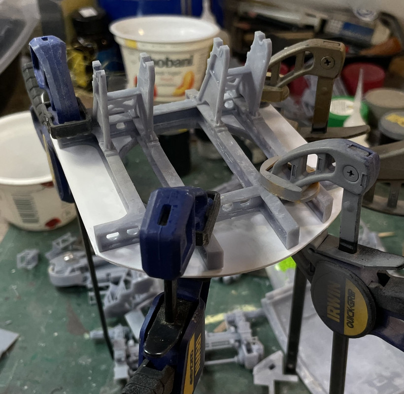
The assembly process has officially begun. I glued the gun house base plate to the underframe. Styrene to UV rensin? Only with CA or epoxy. UV resin is impervious to most common plastic solvent.

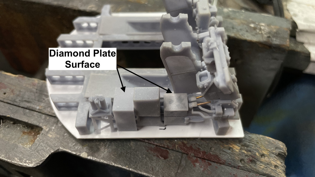
The print package was the flooring pieces. Ryan sent me photos of all the floor plates in the gun house and I was able to reproduce them with reasonable fidelity. I was struggling with the diamond plate. I had downloaded a piece of this from the 3D Warehouse. The artist didn't group the pattern separate from the substrate so when I attempted to trim or enlarge the sample to fit my various piece shapes, I had to deal with the substrate disappearing, reversing faces, or just being a pain in the butt. Finally, I decided to separate the diamond patterns and group them. This allowed me to shape the substrate, which is quite easy, and then drop the diamonds onto the surface. Since they are their own group, I was able to erase them in one tenth the time it was taking before.

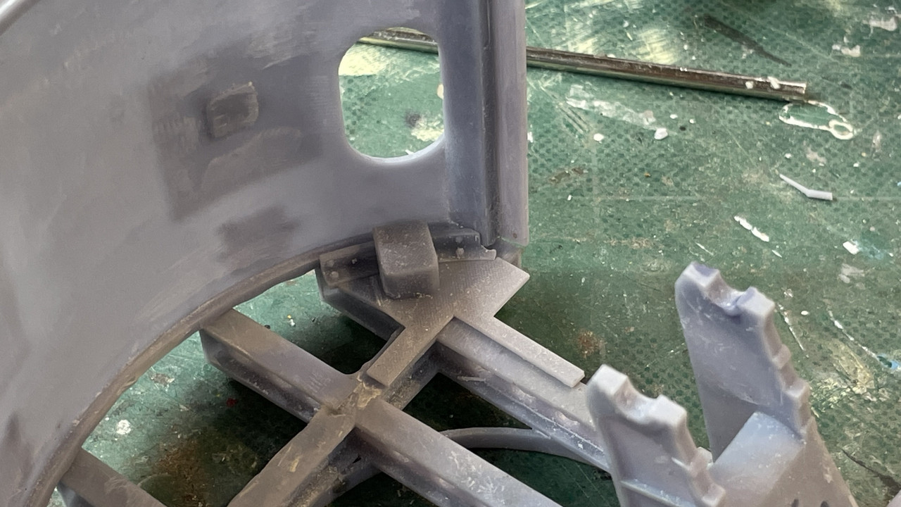
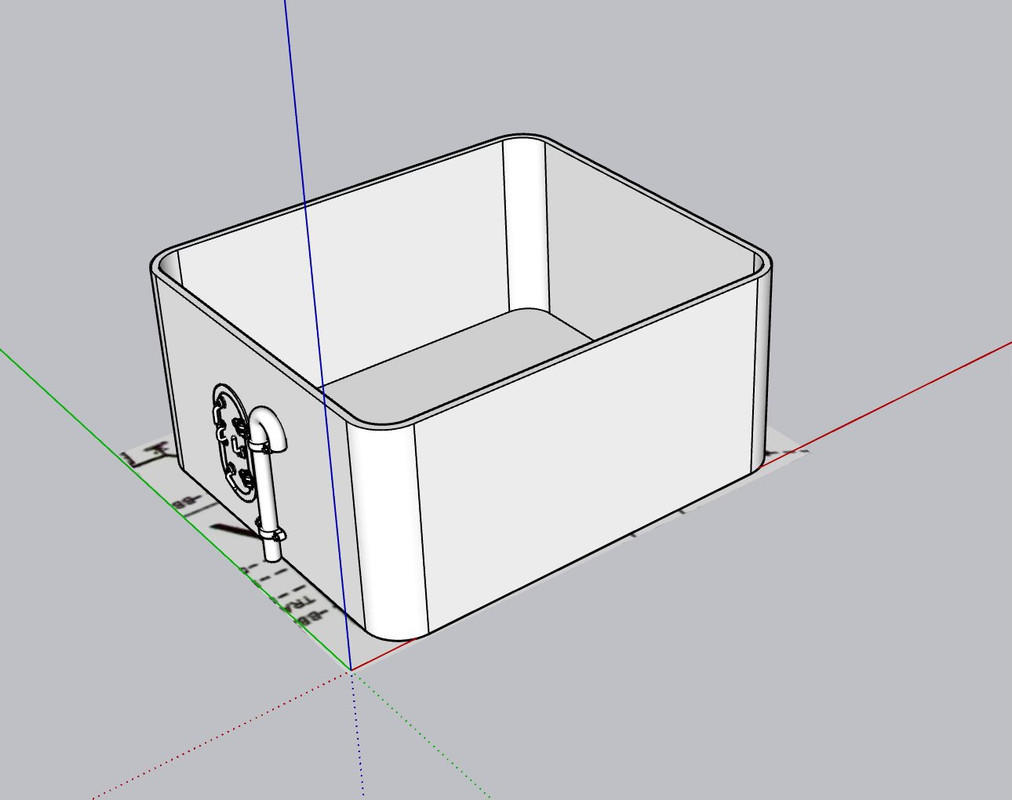
I designed he little box steps at the rear hatch openings to assemble with the curved angle brackets.

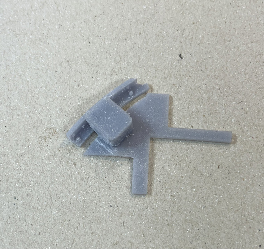
Here's where they fit nesltled into the rear curved wall.

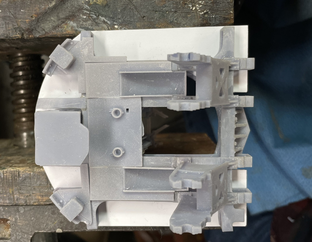
I assembled the floor pieces on the frame for fit and understnading the assembly process.

I'm going to post this now, and then re-open and finish. This site has the habit of exhibiting terrible lag time in typing.

I'm back... 

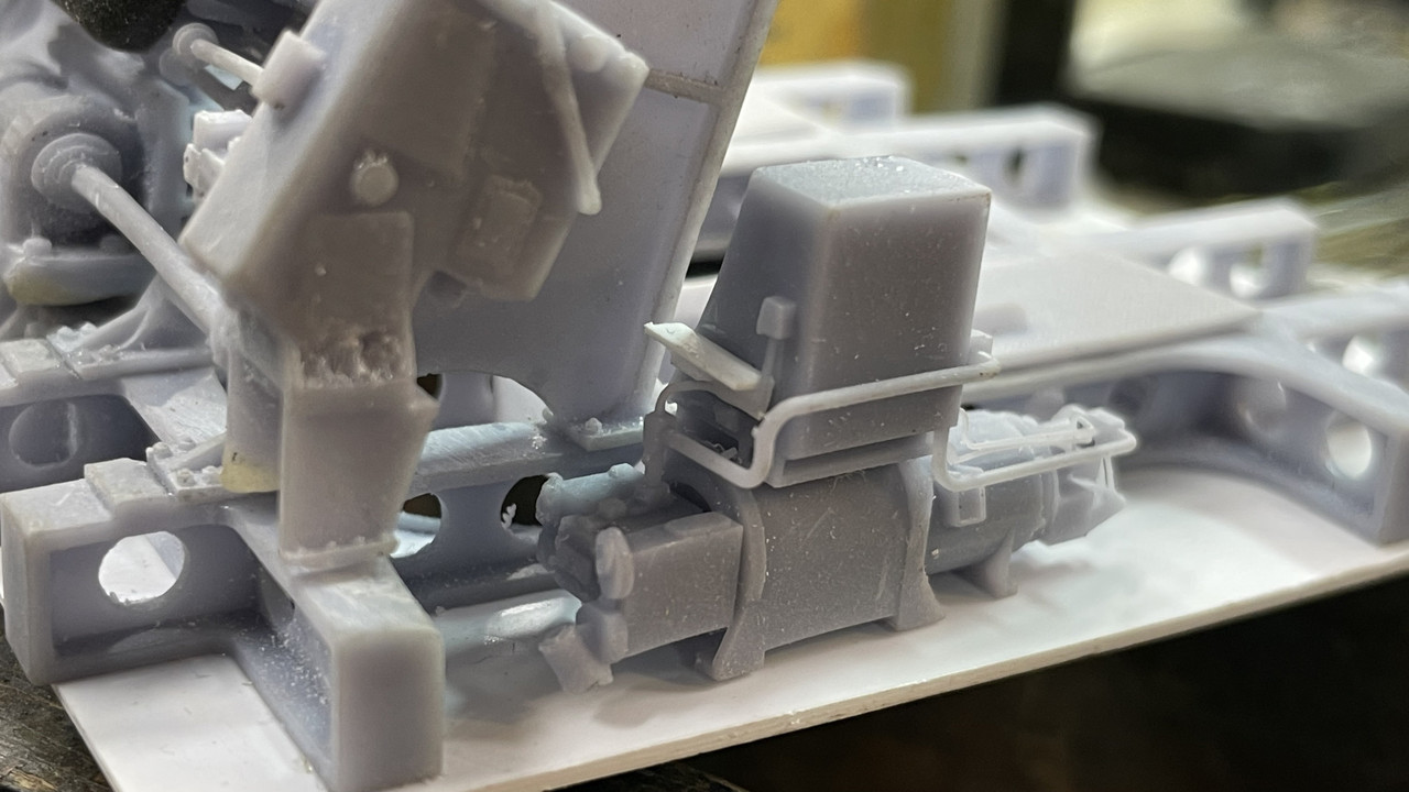
With the base plate in I'm able to test fit and locate all the gun house details starting with the elevation and training pump systems. The training pump was easy since it just has to nestle up against the piping I printed that come out of the b-end hydraulic motor. I marked the base, but when this is painted, those will disappear so I'll probably go back and make some punch marks.

I then test fit the small, diamond-plated flooring pieces.

I did the same for the pointer's side. This was a bit more complicated since the spacing is fixed by the very small floor piece that spans between the pointer regulator, where it sits on a built-in ledge, and the a-end of the pump system. I had to add a small piece of angle to support the aft end of the floor. 

The angle:

And the floor piece. It was very hard to see just how this little bit of floor was attached in the real thing. Ryan's photos only show it from above and all the drawings don't detail it sufficiently. I had to fake it.

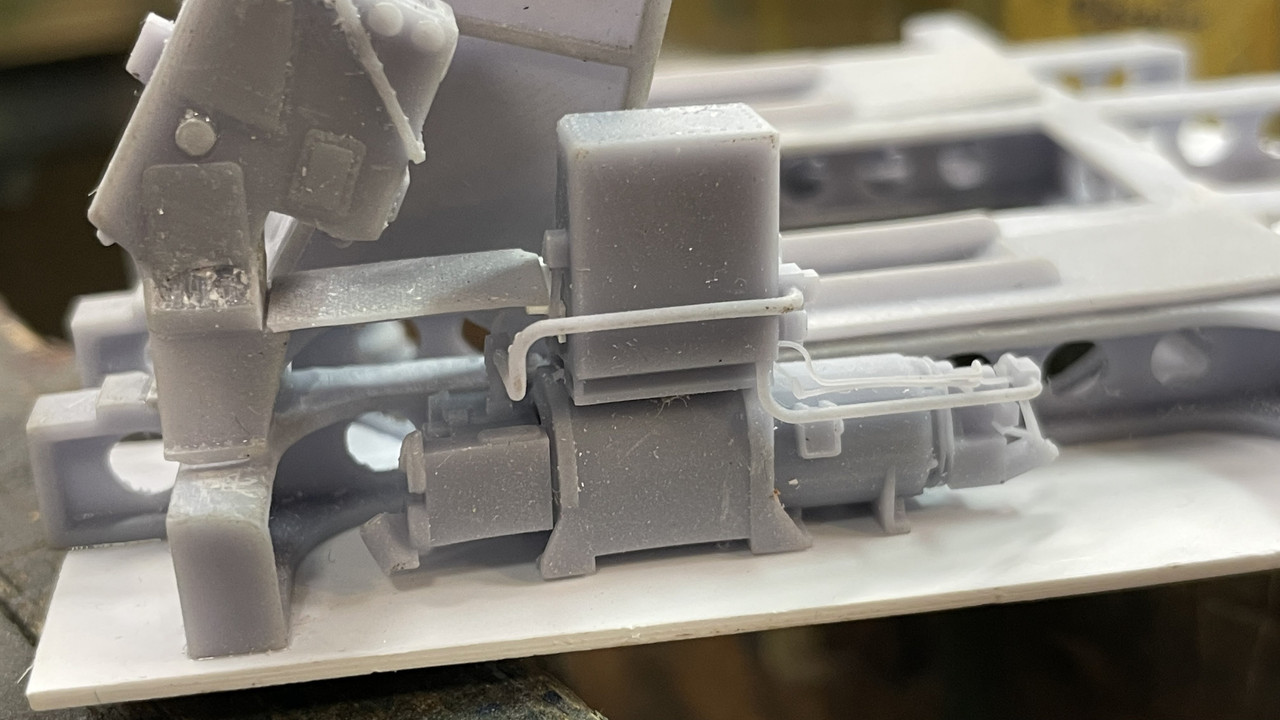
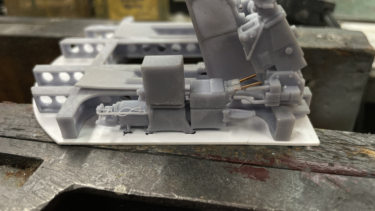
There are hydraulic lines eminating from the a-end of the pump which I will probably add old-school with solder wire.

The entire mechanism assembly needed some possible positioning on the gun mounts. i chose to use 0.022" phos-bronze wire. I broke way too many carbide drills doing this.

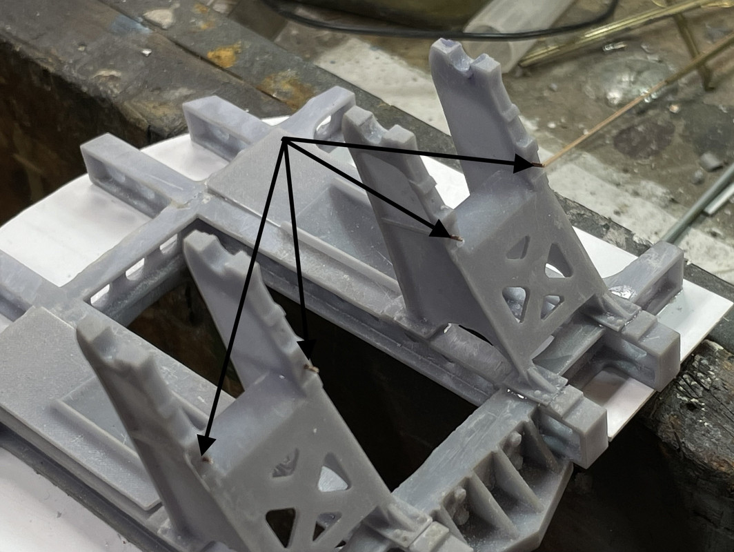
It took some trial and error to get the pin holes in the two pieces so they'd line up. I then drilled and pinned the mounting for the fuze setting regulator. This simple job almost went completely south. I kept breaking the 0.03 2" drills doing this simple operation. I ended up having to drill three diffferent holes to get one without a piece of broken carbide in it.

Fitted, but not glued. This will be glued after the gun trunnion cap is installed on that side.

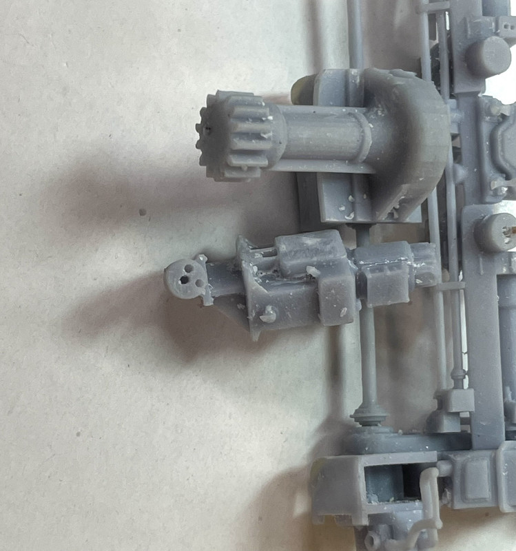
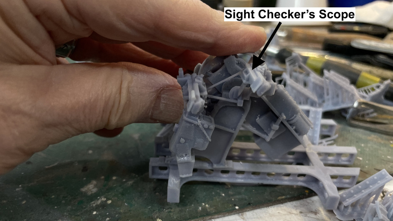
I drew and printed the sight checker's telescope. This station is only used during trainining exercises to evaluate the trainer and pointer proficiency. I made a lug on the mounting point that serves as a trunnion pin on that side. This solved a problem for me.

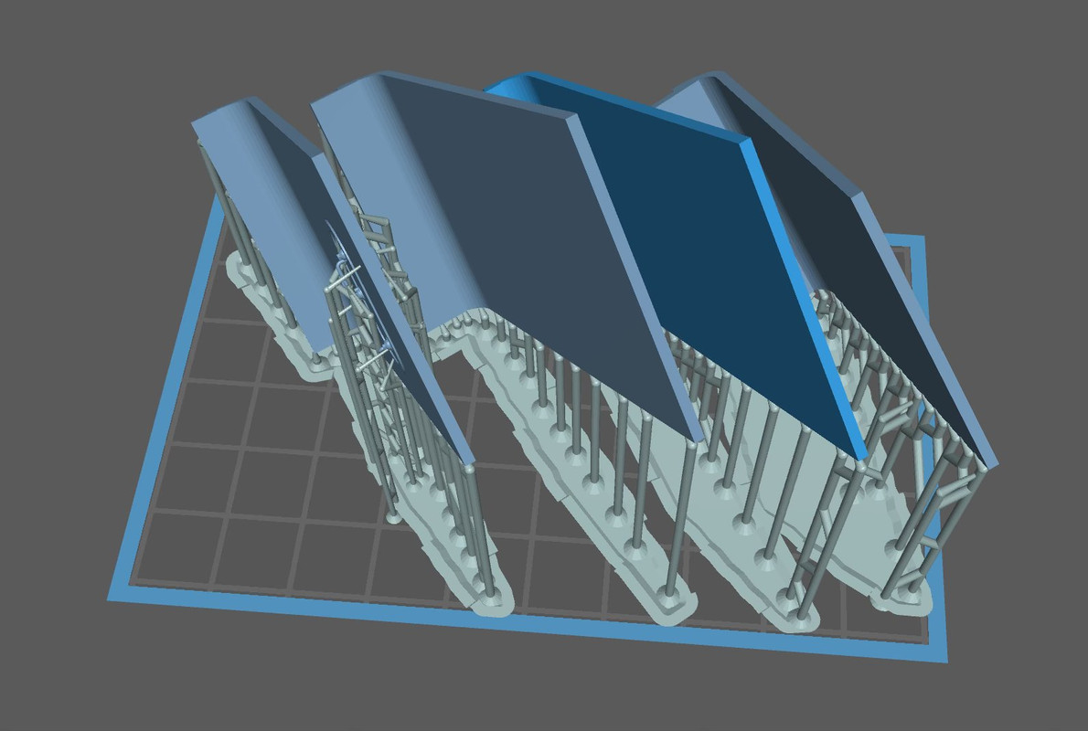
While there's a just a couple of details left to do for the gun house, I'm starting on the upper handling room. I first tried to fit the entire wall structure as a single part, but as you can see, the setup on the printer was not ideal. Way too many supports for my liking.

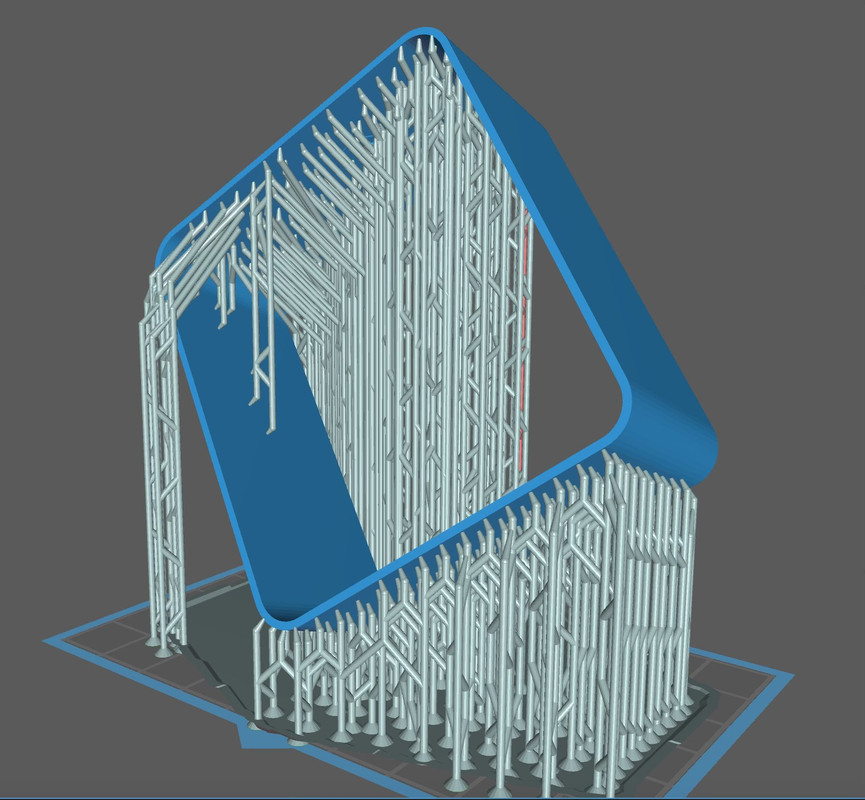
I have a friend with a bigger printer and talked to him about it, but I don't have his printer model available on my slicer. So I went to plan B. Separte the four wall maintaining the nice curved corners. It's those corners that dissuaded me from doing it out of styrene sheet. This permits me to leave on wall open if that's the way I want to approch the cutaway. I did this same scheme when producing the little n-gauge buildings for the exhibition layout. They're printing now and will finish in a couple of hours. Notice, no supports on cosmetic surfaces. Just the way I like it.

Happy to report that the print came out perfect, including the replacement bicycle seat assembly. It's in the ultrasonice cleaner now, and I'll finish them up tomorrow.

  • Member since
    March 2012
  • From: Louisville, KY
Posted by Builder 2010 on Wednesday, December 20, 2023 11:51 AM

Some eye candy showing where the project is right now.

I got good drawings from Ryan showing accurate floor plans for the Upper Handling Room and the Magazine. With this I can finish the design phase.

Also, received good news from my wife's pathology report from her double mastectomy. We are relieved.

  • Member since
    March 2012
  • From: Louisville, KY
Posted by Builder 2010 on Tuesday, December 19, 2023 5:45 PM

With the amazing resolution the printer is finally giving me, I decided to redraw the main gun carriages and re-print. I was very unhappy with the malformed loading trough, the broken piping that I had to replace with metal, and the broken and mishapen controls. It took a couple of attempts (as usual) to get a really good print. I'm getting pretty good at predicting when and how big supports need to go, but I still miss a few. I did that in this case. So I did one print in the afternoon and then another repaired drawing version overnight.

Here's a comparison of the early one done months ago (before the printer adjustment) and the new ones.

Here are looks down the part showing the that critical loading trough. Note: I have not done final finishing on these parts. The nubs you see will be gone before printing. I'm making one gun with the breach open and the other closed. I don't think you'll be able to see them in the finished model.

and the old one. In the first iteration the trough was filled with errantly formed resin. I attempted to grind it out and restore the concave apperance. It was barely acceptable. Notice also that I had to reattach the operating lever on the left and reform the ball end out of Bondic. The new ones have perfectly formed levers.

I also redrew and print the floor trough with the curved space for the gun elevation so it would fit acccuately in the between-frame space.

The gun house work is almost complete. I have to do some more work on floors and platforms, and build the sight checkers telescope and mount. I can then start painting and assembling it. I need more info on the ready service room that lies below. I don't know the floor plan and need direction on what walls get the ammo racks, the circuit boxes, and the access hatch. I also need to know exactly where the upper ends of the powder and projectile hoists lie in the actual space. I had pictures Ryan took of these things, but didn't specify just how they're laid out.


With the new exposure setting on my printer, the supports are much stronger (as well as other tiny details) so on these complex parts, my routine is use the "auto-supports" feature with light supports on the entire part. I then go back and selectively delete light supports in places that would experience higher lifting forces and replace them with Heavy supports. In the past I couldn't trust the light supports. They would break prematurely. With the 3.1 second exposure, they are quite strong and do not break. This really improves both the print success and facilitates cleanup. Most of them can simply be pulled off. I cut them carefully when they're attached to delicate aspects such as levers and handwheels.

  • Member since
    March 2012
  • From: Louisville, KY
Posted by Builder 2010 on Sunday, December 17, 2023 4:37 PM

I was able to get good parts for the projectile hoist after three tries. The first, for some reason, came out 20% over-sized. Something occurred when I made the scaling in the slicer. I don't think it was loading the wrong factor (2.08%), but rather was my entry. I may have double-clutched and got an erroneous value.


It was a shame. It was a pretty nice part.

5IP Bad Proj Hoist.jpg


The powder hoist portion was decent, but the control links were too fine being close to scale size. I doubled their thickness, and also increased the floor thickness by 2X to increase its stability and make the diamond plate texture more pronounced.


The 2nd projectile print, while correctly sized, needed a lot of repair. I broke one of my cardinal rules: Scale thickness doesn't always translate well in the 3D printed 1:48 world. I made the columns prototypically hollow with the twin bores extending full length. The resulting wall thickness was so thin that it ruptured all over the place. It was actually translucent. I attempted to rebuild them with Bondic, and while structurally stronger, looked awful.


5IP Failed Hoist 2.jpg


5IP Failed Hoist 12.jpg

As with lots of SU projects, fixing is often more difficult than making it right the frist time. And this was no exception. Took about an hour to fill the bores. I also took the time to strengthen some other dubious connections. While doing this I also fixed a lot of drawing stuff like hidden layers that didn't do anything.


I was rewwarded with a really nice print. I only had to go back and reattached some tiny links and further strengthen the door hinges.


5IP Proj Hoist Print Success 1.jpg

Get a load of those very fine pull handles compared to that #11 blade. I was impressed. I also added some mid-run supports for the long-run link rods so they would have a better chance for printing and after-printing survival.


5IP Proj Hoist Print Success 2.jpg


5IP Proj Hoist Print Success 3.jpg


I had to notch the floor at the front corners to nestle over the gun mount's rear feet. I was worried that after all this work I couldn't install them, but if I moved the powder hoist as far aft as it would go, carefully inserting the projectile hoist sideways between the frame rails, I was able to lower it and twist it into position. I did have to relieve the width a bit at the cross-girders to make it a slip fit.


5IP Hoist Complete Test 2.jpg5IP Hoist Complete Test 4.jpg


5IP Hoist Complete Test 3.jpgThis was, without a doubt, the most complex parts I ever produced, and is the apex of complexity on this model. With it successfully done, I can breathe a bit easier.


I drew and printed the floor pans that sit between the frame rails under each gun. These are sheet metal affairs in the real deal, and have a curved floor that follows the arc of the gun. I made perfect prints. Perfect, but for the fact that they were about 5 scale inches too wide! I used the drawing of the frame rails for sizing assuming that my printed part was the same. For some reason, it is not. I will redraw and reprint. They weren't the only thing that was too wide for the frames rails. The gun itself was too wide to drop down between the rails. More about this later.


The oil filters and pedestal were easy to draw and print. I drew the tiny hand screws on their caps, not knowing if they'd survive printing and support removal, They did!5IP Gun House Auxiliaries 1.jpg


I added more stuff and took this image. Starting to get interesting!


![5IP Gun House Auxiliaries5IP Gun House Auxiliaries 2.jpg


About the guns…


I was unhappy with the prints that I had. The entire trough didn't print well, and the drawings were a mess with lots of hidden layers and voids that lead to print troubles. With the new print settings I was confident that I could do better. The wrong width gave me an excuse to attack it. Like before, making changes can often be more difficult than starting new, but in this case I did sort of a hybrid attempt using some old and some new. Spent all of yesterday afternoon and more time today to get the internal and external geometry right. I have a lot of time to draw as my wife is recuperating from major *** surgery. She had *** cancer 16 years ago, and it came back. The best of bad news is that it appears to be self-contained. She had full diagnostic scans that were all negative and the surgery went well. So we're very optmistic.


I'm having a lot of SU crashes. Sometimes it occurs when doing tricky things like using BoolTools2 on big complex interfaces, but others occure just when I've made a couple on moves. I never lose too much work since I'm doing auto-backups every minute. But it's annoying!


For some reason, connecting the straight side walls to that compound curved rear panel drove me nuts. I know how to do it, by intersecting the flat into the curves and removing the intersected parts, but it was a lot harder to do than it should have been. The assembly was built from a bunch of geometries that would cause surfaces to disappear unannounced if I erased the wrong line.


This geometry was the worse part. I'm very happy with how the curved trough is now designed and it should print perfectly. I still have a lot of stuff to add on, but I'm not worried about that.

  • Member since
    May 2009
  • From: Poland
Posted by Pawel on Sunday, December 10, 2023 3:00 PM

Hello!

Well it looks like jungle!

Now congratulations on being able to draw up something like this. I hope to reach this level of skill some day!

Good luck with your 3D print and have a nice day!

Paweł

All comments and critique welcomed. Thanks for your honest opinions!

www.vietnam.net.pl

  • Member since
    March 2012
  • From: Louisville, KY
Posted by Builder 2010 on Sunday, December 10, 2023 2:27 PM

Thanks!

While it took less time to design the powder hoist portion of this system, it still took 6 days to do it. It is singularly, the most complex SketchUp work I've ever done. This still conforms to my goal for each project I take to push the envelope further and keep increasing my skills. It had all the same ambiguous drawings as the projectile side, plus some more complex geometry, little links that had to be ferreted out as to their purpose and destination. And finally, I had to keep imagining how it was going to print and ensure that every surface and every little appendage was fully solid and attached properly to all the other parts so it would print with integrity. When it was all done, I did one final fit into the master turret drawing and found that the powder hoists were spaced about 2" on each side too wide. Luckily, moving them inwards didn't create any new problems. They have to slip between the main frame rails. I could have trimmed the rails during assembly, but that seemed like cheating.

I incorporated that fully-modeled diamond-plate floor with the hoists to facilitate wrapping the plates around the protruding hoists and to add another piece of structure to keep their spacing. 

This view shows the lower portion of the projectile hoist with their respective access doors. I modeled one open with projectile ready to go up to the gun house and the other closed. This is an accurated depiction since its upper doors are open with another projectile ready to be placed in the gun tray.

Those manual handwheels are going to be very delicate. If they don't hold up when printing with the entire assembly, I'll print some separately and add them later.

The reverse view shows the powder hoists and the little aspect that pokes through the floor. There is an operating foot pedal that's also above the floor plates.

I learned how to find and edit materials in the V-Ray rendering engine that's part of my new SketchUp installation. It's more complex to operate then my previous add-on renderer, Podium. It's more sophisticated, faster (much faster) and does a much better rendering job. 

I gave up on the idea of printing this beast in one piece. Instead I designed the two pieces so they will index together during assembly. I did this by adding some more structural steel at the bottom tying the two powder hoists to the central column. While this is not prototypical, I took artistic license to make the model work.

I also split the floor panels and added a lip to align and give purchase to the asembly joint.

Here's the mess of supports needed to set it up for printing. 

It's on the printer now and will be done after 10pm. I'll know then whether it's successful or not. Then I'll have to figure out how to remove all those supports without wrecking anything. Wish me luck. 

This was the last of the really complicated parts on the project. The rest is downhill. 

  • Member since
    October 2016
  • From: Louisiana Gulf South
Posted by Mrchntmarine on Saturday, December 9, 2023 5:45 PM

Builder 2010

It took over a week to draw the projectile hoist. It's complex, ambiguous in parts, had penetrations and curve cuts that needed shape cutting, and finally, required some major rework to get it as right as I can.


All I can say is, THANKS for posting and sharing. Very very interesting. Wm. 

Keep on modeling!

All the best,

William

  • Member since
    March 2012
  • From: Louisville, KY
Posted by Builder 2010 on Monday, December 4, 2023 10:24 PM

It took over a week to draw the projectile hoist. It's complex, ambiguous in parts, had penetrations and curve cuts that needed shape cutting, and finally, required some major rework to get it as right as I can.

The rework was this. 

This central core had gotten so messed up with multiple diameter layered in on each other which created voids, reversed faces, and other anomalies that I couldn't get a decent solid image on the slicer in my tests. I finally bit the bullet and stopped screwing around with it and redrew it from scratch. This time it was perfect. All the discontinuities that plagued me were now gone. 

I also figured out the routing of the handwheel linkages. Speaking of handwheels, I wanted to make sure that they would print perfectly since they're quite frail even when perfect. If there were joints that weren't true, it wouldn't hold up. That took a couple of hours.

And speaking of hours, it took an entire afternoon to get the doors right. Again, when I put them on the slicer surfaces were showing up as invisible. The "Solid Inspector 2" add-in kept showing surface interface irregularities. I when inside the object using the x-ray function and removed all non-functional surfaces and made sure all the face surfaces were perfectly tight. I was rewarded with beautiful objects in the slicer.

One of my other forums is SketchUp's. I post this in its entirety in five forums. The readers in the SU forum are expert artists and offer good suggestions. One was to not scale the 1:1 object in a 1:48 file, but instead, just load the 1:1 object in the slicer and do the scaling right there saving a whole range of copy/paste operations. With this massive file, those take a lot of time. Another suggestion was to set a camera scene facing directly at the tiny 1:1 component so with a click of the track pad, the 1:1 is instantly brought into the center of view. Otherwise, I have to keep zooming in many times to get the object to fill the screen. These zooms take a lot of time with big files.

Here's the finished object Front view:

And the rear view:

I'm going to attempt to print at least this part of the hoist system as a single part. Here's the part sitting on the slicer. It seems perfect. Will all of the intricacies print... who can tell. I only know when it's finished. That's the fun of 3D printing.

I can now work on the powder hoist part of the system. This should be easier since there is no fuze setting linkage, only a single channel per side, sinpler doors, etc. There is one complication; the chute follows a curve and seems to change diameter.

  • Member since
    March 2012
  • From: Louisville, KY
Posted by Builder 2010 on Thursday, November 30, 2023 10:22 PM

Thanks guys! And enjoy your new sofa. 

I found out that the fuze setter regulator that I modeled last week was an older version that was NOT on the Iowas. At first I thought, "Who's going to notice", but then my AMS took over and I had to draw and print a correct one. Ryan appreciates this.

It printed nicely. I also printed the opposite hand versions of the optics shields so I can pick either open or closed on both sides of the gun shield. And I printed some scale 5" projectiles. I'm going to need a bunch of these since they'll appear in the gun, the hoist the ready service room and the magazine.

Then it was full-steam ahead on the projectile and powder hoists. As complicated and confusing the sighting mechanisms were, this one is more so. Not only are they complicated beasts, but every illustration I have shows me something different. I sometime don't know if I'm looking at the same mod number. I know there are slight differences between the mount versions in lots of ways and these could differ as well. It's even confusing determining where the central tubular column sits. Is it in between the two projectile hoists, slightly behind them or equally located in the center between the projectile and powder hoists? I've asked Ryan to cast the deciding vote.

Even so, I'm a couple of days away from finalizing the projectile hoist part and will move on to the powder hoists. Regardless how the center column is situated, it appears that it provides support to all four hoists. In additon to getting the details and relationships nailed down, I constantly have to keep in mind how it's going to print and finally how am I going to get it all together. I found some actual diamond plate in the SketchUp 3D Warehouse that the artist has actually drawn the pattern in 3D so it can be printed. I'm going to attempt to print the hoists with the flooring in place in a single piece. I want to do it this way to ensure that it is all perfectly aligned. I test the part periodically in the slicer to make sure that it's all solid and will fit the printer as it gets bigger. I pay special attention to all those rods and connectors to make sure they're supported in various places (even if it dosen't conform perfectly to the prototype) and they're all perfectly contected to all the points and surfaces they're supposed to be.

Here's what it looks like now. 

First, a screen print off of SketchUp: The tiny thing you see in the red square is the exact same object 100X smaller. That's actually real-world size. I'm drawing the object 100X enlarged to prevent any "small curve segments" that SU runs into. The entire drawing is saved as a component. Anything I add or modify on the big version duplicates instantly on the 1:1 version.  I use  the 1:1 version in the master drawing of the entire model, and it's the one that's exported to the scaled drawing where I reduce it again, by .021 to make it 1:48 scale for the printing and the actual model. By using it as a component I don't have to copy and scale it every time I want to use the 1:1 drawing. it's always there and up-to-date. It's so tiny that it's easy to lose it, so I put it on that big red square so I can easily find it.

And the same drawing rendered in V-Ray:

Still to do: The lower doors, and the power and hand-operation linkages. Part of the power system is drawn, but there's still more to do. I've made the center column hollow and will use it as a wire chase duplicating its real world purpose.

  • Member since
    October 2019
  • From: New Braunfels, Texas
Posted by Tanker-Builder on Saturday, November 25, 2023 12:27 PM

OOH Boy!

      I am glad that I wasn't a Gunners Mate! Being in D.C. was bad enough. Can you imagine what I had to learn? I could build a frame only with stringers and stiffeners of a Gearing,from the Keel up. On the gun I only got to squeeze the trigger! Doing what you are doing is not only fascinating, but to the uninitiated a real high tech job. Love it and keep going!Gotta go-New sofa is here!!!

  • Member since
    May 2009
  • From: Poland
Posted by Pawel on Wednesday, November 22, 2023 3:38 PM

Looks like you're really busy! But you are cranking out lots of high quality stuff, congratulations! And thanks for sharing!

Paweł

All comments and critique welcomed. Thanks for your honest opinions!

www.vietnam.net.pl

  • Member since
    March 2012
  • From: Louisville, KY
Posted by Builder 2010 on Wednesday, November 22, 2023 9:45 AM

It was 11 days ago when I put this complex sighting system on the printer. Since then I did five different runs. Each had it share of problems from total failures when my build plate has lost its holding power, to failures due to mistakes in my design or drawing execution. Today I was able to get a fully usable part. I had to make some minor fixes using Bondic, but all in all it will do well. Meanwhile, I had designed and drew the Sight Setter's Regulator and incorporated it into the part's design and printed it as an integral unit. The Sight Setter's Regulator adjusts the two telescope prisms so they match the aiming data sent down by the gun directors. In normal operations all of these settings would directly operate the guns, but everything has a manual backup.

This is viewing from the turret front. The front armor shield normally hides all this, but I will cut it away so some of it will be visible. It's pretty cool in its complexity.

And the rear view that will be seen from the turret's interior.

After doing a trial fit I was rewarded with a pretty good result.

And the interior view.

While this was printing I designed the Fuze Setter's Regulator. This assembly is also connected to the front complexity, but is very close to the starboard side gun mount. I decided to print it as a separate part and will install it after installing the guns so I can get the trunnion cap in place. This device is used to translate the firing timing from the gun directors into the fuze setting system in the projectile hoist. It was mostly obsoleted when the proximity fuze was introduced later in WW2.

I've created masters for decals for all of these systems to simualate their dials.

I redesigned the acess doors with the hinges in the open position to show the insides and how the system were maintained. I also redesigned the optics hood with the open shutter so the shutter had more beef in the hinge so this fragile part had a good survival chance.

I'm now working on another complex unit, the projectile hoist. There are two of them, but they are not mirrored. They extend over two decks since they start in the Ready Service Room (RSR) before the gun house, pass through the center and end up in the gun house. I'm creating them this way. There are some structural steel cross-braces that support them.  They do not go to the RSR's floor. They hang above it and the whole deal rotates with the turret. Unlike the big guns where the entire deck rotates to keep the hoist aligned with their respective guns, in the smaller 5" application, the hoist rotates, but the RSR is stationary.

It's very complicated to created curves on already curved surfaces in SU. You can't do the simple push-pull extrude operation because that only works when the two sides are parallel. To cut a curve into another curve, you have to created a negatively-shaped "cutter" and use it with an extension called BoolTools2, to remove the interferece area and create the shaped surface. You can also do this directly in SU with "Intersect Faces", but you have a lot of clean up work since it gives you the cutting line, but leaves an open space that you must hand draw all the interconnecting lines to create a closed solid.

While doing all this I finally finished that cute little n-gauge display layout that's going into the Newtown Hardware House in Newtown, PA. I was able to accurately model four Newtown buildings. These were drawn in SU using actual and Google Earth images.

I have the Trumpeter 1:32 F35b on layaway at Scale Reproductions, Inc. I was waiting for the most complex F35 to finally come out in 1:32. While I'm not a big Trumpeter fan, they're the only one making this model now, so I'm going to get it. It will be 2024 when I start it so stay tuned.

Also, with work finally complete on this model rr commission job, I will be back at work on the AH-64D. It's been sitting next to me gathering dust, but I haven't forgotten about it.

  • Member since
    March 2012
  • From: Louisville, KY
Posted by Builder 2010 on Wednesday, November 8, 2023 10:54 PM

This is what two weeks of drawing produces. This was probably the most complex SketchUp drawing task I've ever tackled. In addition to just the SU idiosyncracies, there was also the challenge of getting all the shafts and connectors to align in some reasonable fashion so they would resemble something that could actually exist in the real world. And then there was getting this stuff in such a way that it would successfully print. As a result, some of the operating pieces are touching other surfaces intentionally so as to add structural integrity to the printed object. I'm attempting to print as much of this mass in one piece as possible. Orginally I was going to use metal rods for the rods in the model, but with my printer improvements, I think the printer is up to job to print them all and make them relatively straight. We'll see.

And the front view. 

And how it's going to go on the printer. Lots of corners and curves that needed specific supports. The flanks of some of the tiny bolt heads show up as needing supports, but I chose to not attempt it. The support removal would destroy the detail anyway so we'll just see how it all turns out.

I'm going to put it on the printer tomorrow.

  • Member since
    March 2012
  • From: Louisville, KY
Posted by Builder 2010 on Thursday, November 2, 2023 11:03 PM

Just a quick progress report. I've spent over a week working on the elevating mechanism and still not done. Nothing about this one is easy to understand or easy to draw. What makes matters worse is the real ship, most of this stuff is buried in the front of the turret up against the lower portions of the armored front and you couldn't get near it to make any real world measurements. I draw it in a separate file, at 100x full size. I then copy it, reduce it to 1:1 scale and export it to the master file. I then fit it to the gun stands and the shell sides. Nothing on the part is a right angles to the SU main axes. I have to figure where the parts need be separated for effective printing.

This is a view from the rear which is kind of what you'd see if you actually went into the turret.

All of this is created with images like this:


  • Member since
    March 2012
  • From: Louisville, KY
Posted by Builder 2010 on Monday, October 30, 2023 9:32 AM

Thank you!

Yup! Or had some engineering drawings. All my drawings come from instruction manuals. that said, much of the apparatus in this turret is located in places where taking such measures would be nearly impossible.

  • Member since
    May 2009
  • From: Poland
Posted by Pawel on Sunday, October 29, 2023 4:52 PM

Hello!

Lots of good work here! I bet you wish from time to time, to be able to get into the real one for a moment and just measure some of the details with a tape... I know I hat that dream many times when I was drawing...

Good luck with your project and have a nice day!

Paweł

All comments and critique welcomed. Thanks for your honest opinions!

www.vietnam.net.pl

  • Member since
    March 2012
  • From: Louisville, KY
Posted by Builder 2010 on Sunday, October 29, 2023 4:03 PM

Work continues on designing the very complex (for me) Elevation Station. This assembly includes all the input controls, the output shafts, the optical telescope and its linkage, the elevation gear housing and the connecting shafts to the other gun and Sight Setters station. There are no right angles! Making it more complex is the coupling casting that ties the elevating regulator column to the gear housing. This thing. This, BTW, was not correct as drawn here.

The reason for all this confusion for me was none of my referece drawings showed the entire part, nor were there any that gave me a true understanding of its geometry. It took well over an hour to get this far. I even sent out the word for help from some other SketchUp, but didn't get a response. Here's what I had to go on.

I persisted and eventually landed on a shape that works and looks credible. Whether it's actually correct is a totally different question.

I then took this assembly with the beginnings of the gear housing and put it into position in the gun house on the master drawing. This is what I found.

The gear house (and associated shafting) was too low. I also found from a verticle perspective drawing of the turret interior, that the shafting an its associated apparatus were to far left. This is all the result of not having a single orthographic diagram of the equipment design or location. Some are perspective and others are isometric, but locating accuracy was very difficult to achieve. It just a series of aproximations.

I'm satisfied that I've got it right... enough... for now.


The Trainer's station is similar in design to this one and I'm going to use the same "casting" to join it to the other gun's elevating housing. There is another ambiguous part that I need to design. It sits on the gun side of the housing near the bottom and contains a ton of complexity of which I can make no sense. Problem is when I enlarge the drawings to bring out of the detials they disappear since the images were screen prints of scans of a manual and have no resolution when magnified. Again, it will be mostly quess work. I do have a picture of the Trainer's station with this component that shows more detail. I can cannabalize off that one. 

  • Member since
    March 2012
  • From: Louisville, KY
Posted by Builder 2010 on Tuesday, October 24, 2023 8:32 PM

My first prints of the elevation and training pump systems was okay, but a couple of details didn't form and it bugged me. Here's the first attempt.


You probably can't find the errors, but I know they were there. I tried them on to see how they looked sitting in the framing. And they looked swell.

When I went back and evaluated the support scheme, I found that I misplaced the tiny support on the upper side of the detail, not the bottom-facing apex. This caused the detail to not form correctly until the build reached where the support was. This is support skills 101: the support goes at the bottom-most point what would start to form and create an island. There's a moving line in the slicer that helps you identify this contact point. In this case, I missed it a bit.


When I repositioned the errant supports I got a really nice print. I also moved some supports or made them smaller where they were difficult to remove without damaging the model.

Those piping details are very, very fine. The phos-bronze wire is showing where the links are going to connect to the regulating pedestal. They will not be this long. I pre-"drilled" the holes in the drawing so I could easily open them up with a 0.032" drill.

The new setting is amazing. It's like learning to 3D print all over again. I'm also reprinting the foot rungs since the new setting will make a truer and stronger part, plus a less warped base that I'm using as a drill jig.

  • Member since
    March 2012
  • From: Louisville, KY
Posted by Builder 2010 on Sunday, October 22, 2023 6:16 PM

The Elevation Pump/Motor Hydraulic System shares the same motor/gear box/reservoir with the Training System. The output end is completely different and the units are mirror-images of each other. But having successfully crafted the one, drawing the other went quickly. Both just came off the printer and, with the new exposure settings, the detail is exceptional and all the piping is intact and tough. I'm very happy with these results and it tells me that anything I can draw for this project with print as I want it.

I'm now wrestling with the human interface portion of these systems, the pointer's and trainer's regulators. These, like the rest of this job, are not easy to visualize or draw. All the pictures I have are persepective images and therefore, I can draw directly on them. There are very few surfaces that are parallel to the SketchUp axes, and many of the corners and junctions are rounded/curved. None of this makes it an easy SU drawing project, but I will persist. Ryan Syzmanski is enjoying seeing all these components separated from the complexity of the insides of the turret.

I'll post the finished parts tomorrow.

  • Member since
    March 2012
  • From: Louisville, KY
Posted by Builder 2010 on Friday, October 20, 2023 5:24 PM

Work progresses...

I designed the Training Gear hydraulic plant. This sits down between the girders on the gun house's right side behind the Trainer's seat and regulator. Luckily this one is drawn in profile in one of the cross-section images I found so I could get the profiles down. I've scaled these drawings so they are representing correct lateral dimensions. 

There are two output shafts that extend out of the end and I probably will make these out of correctly sized wire. It was gratified after finishing the drawing that it fit perfectly in the space it was supposed to. I have an add-on that facilitates making those neat curved edges. Also, SU is pretty easy to draw complicated pipe runs once you know what you're doing with connecting lines and adding curves to them.

Here it is dropped into position.

Next up will be to design this units hydraulic counterpart, the Elevation Gear Hydraulic Plant.

As in the big gun's turret, all the systems are driven by hydraulic motors with the pressure generated in a remote motor/pump setup. In the case of the big gun, the motor/pump (A-end) was physically remote from the hydraulic motor (B-end), but in the case of this smaller turret complex, the motor/pump was directly in line with it's b-end hydraulic motor.

With my newly refined printer setup, I have no doubt that all that delicate piping will render. It should look pretty good.

  • Member since
    March 2012
  • From: Louisville, KY
Posted by Builder 2010 on Tuesday, October 17, 2023 7:21 PM

And thank you. Just when I thought I had it nailed down last night, I tried the drawing again in the turret, and this time viewed it from a different angle and found this...


I had to re-configure the ducting that entered the handling space below. It had to clear the gun, all framing girders and enter the space through the center ring. What I came up with worked, but I have no idea how accurate it is. Ryan's pics don't show this particular duct. I also took the time to draw the blower system and set it up to print as a single assembly. The new printer settings are working perfectly and I had a lot of confidence that all of the parts would render. 

The print is done and mostly cleaned up. I may still have some trouble with the upper outlet pipe. I may be interfering with the right gun's curved shield space. Everything printed perfectly, nothing warped or broken and all the bolt heads showed up.

Now I just have to figure how to shoehorn this into the model during the build...


  • Member since
    May 2009
  • From: Poland
Posted by Pawel on Tuesday, October 17, 2023 2:31 PM

Hello!

It's good to hear you're moving on with this project.

I just love this line drawing:

Builder 2010


That ventillation system really looks complicated, good job fitting it inside. I would really need your help on that M60A1 Tank interior!

Good luck with the construction and thanks for sharing, have a nice day!

Paweł

All comments and critique welcomed. Thanks for your honest opinions!

www.vietnam.net.pl

  • Member since
    March 2012
  • From: Louisville, KY
Posted by Builder 2010 on Monday, October 16, 2023 6:00 PM

It's been a while since I updated this post. I have been working on five projects at once; three of which are commission. This technically is a commission although I'm not charging anything for it. When I last left you, I had to rebuild my 3D printer. I installed a new LCD panel which went well although more trouble than I thought. It's printing well now. I also found out recently, when testing my exposure setting with a new test article (Starship from 3DRS) that I was under-exposing my resin by 20% since I got this machine more than a year and a half ago. When I initially calibrated it I used a simple flat calibration piece and derived 2.5s per layer. With this new part, 2.5s didn't work. I printed a test from 2.1s to 3.1s by twos. 3.1 was it! It explained why I was getting such warpage and support breakage. When exposure is too short, the resin doesn't have enough cure time to develop structural integrity. The warpage is due to the amount of hardening that still needed to take place in post-curing. And the support breakage (a resultant delamination) was due to the resin being too weak to perform.

During all this, I was designing the ventilation system that goes into the gun house. It's a tricky design since the drawing is unscaled and undimensioned. 

I had designed the overhead I-beams (wrong, I might add) and then Ryan came through with a passal of images showing the entire ceiling of the gun house (also good views of the ready service room and magazine). I have four beams. There are only two. I also had lateral beams. There are none. I also needed to know how the cross vent passed around the I-beams. They don't pass, they go through. Makes sense since head room is so limited. I drew the assembly and decided to print it all in one go, I-beams included to ensure it all lines up. I did't design the blower system yet as that will be a separate part to glue in.

This was the image that told me what's what.

I placed my assembly into the gun house drawing and kept moving parts of it around until the ducting cleared the guns and nestled into the I-beam.


I scaled it .021, exported as an .STL file and loaded it into the slicer. My first setup used a 100% raft coverage area. The Tall aspect on that little raft started failing about 1/3 through the print. I could see it detaching from the build plate since the plate has risen enough to be clear of the resin level in the vat. I stopped the print knowing it would just be a waste of resin.

I redesigned the arrangement with a more substantial raft. I am having no problem with build plate adhesion and blamed the strange setup for the lost of attachment.

This will off the machine later tonight so I won't know if it's good until tomorrow. Once the ventilation is squared away, I'm going to dig into all the electro-hydraulics in the gun house, and then onto the ready reserve room below. With exposure change, I'm much more confident about fine details and small piping rendering nicely. I may reprint some of the more dubious parts I've produced so far. I haven't glued or painted anything yet so it's just time and some resin.


  • Member since
    March 2012
  • From: Louisville, KY
Posted by Builder 2010 on Friday, September 8, 2023 4:38 PM

I'm giving Ryan a choice of how to display the innards of the gun house. My first approach would be a cutaway, but while not to difficult to execute, it doesn't show all that much unless you turn it into Swiss Cheese. Ryan just texted me. It will be the cutaway version which follows the theme of the 16" project.

The second approach could mimic yesterday's photo showing the entire armored casing in the air above the open gun house. This would show almost everything, but would have to be suspended above and it would raise the enclosure height. I could use acrylic rods to support. Lighting would require some visible cabling. In order to raise the casing, the guns need to be elevated, as they are in the photo.


The last is the most elegant and also the most challenging: making the forward parts of the gun house out of clear acrylic. I would leave the curved wall as it is. While I have clear resin, optically it wouldn't be very good and not any value. Acrylic is very clear and shows no distortion. Gluing it together so it really clean is the first challenge. The second is cutting out the small parts with true and square edges.

So I'm also asking all of you. Which do you prefer?

I finished cutting out all the casing parts and trued up all the edges. I cut the telescope holes in the right and left sides, the ofc's hatch opening, and the remaining access hatch opening. I clamped both angled face pieces together so I could finish shape the gun slots so they aligned perfectly.

To cut the telescope holes, I drilled a series of small holes through the drawing, and then used a larger drill to make nice rounded corners.

Here's all the finished parts ready to be assembled.

 s

Since I don't know which version Ryan will pick, I did some future planning... While all the casing parts were in the flat, and they're all accurate, I clamped them to a nice piece of 0.080" acrylic that I had laying around and traced all these parts so I'm ready to cut them out if we go that way. If fact, regardless of Ryan's choice I may cut out all those parts and see how well I can finish them. Having it clear would be pretty neat. You can barely see the scribed lines, but they're there. Now that I know Ryan's choice, I'm going to try and construct this version anyway since I've kind of wrecked that part of the acrylic with my scribed layout lines.

I also went at the back of the curved wall and removed that lump. I used a cutting disk to remove most of the stock and then my micro-power sander to finish. I may add some filler to hide all the tool marks. 

With the acrylic in the wings, I can continue to construct the regular casing. I won't do the cutaway until after it's built if i go that route, so I won't be getting too far out over my skis.

My new LCD panel arrives today and I've already stripped the old one out of the machine in anticipation. I hope it comes with a new under class plate since I cracked it a bit getting it out of it's depression. It too is held with adhesive stirps. Should be running next week. It has to be running next week. It's on the critical path of two major projects.

Y'all have a nice weekend!

JOIN OUR COMMUNITY!

Our community is FREE to join. To participate you must either login or register for an account.

SEARCH FORUMS
FREE NEWSLETTER
By signing up you may also receive reader surveys and occasional special offers. We do not sell, rent or trade our email lists. View our Privacy Policy.