SEARCH FINESCALE.COM

Enter keywords or a search phrase below:

M4 Sherman 75mm Normandy, Dragon # 6511, Setback...

20488 views
30 replies
1 rating 2 rating 3 rating 4 rating 5 rating
  • Member since
    July 2007
M4 Sherman 75mm Normandy, Dragon # 6511, Setback...
Posted by Utoshita on Wednesday, August 26, 2009 1:09 PM

Dear All,
Time for me to start my first build log Shock [:O]

Please excuse the pore quality of the pictures; I hope that I will be able to improve.

This is my first attempt at US WWII AFV's.

I have had a lot off help already from this Forum, I hope you will stay patient with me and continue to provide Your support.

First a couple of immediate issues;

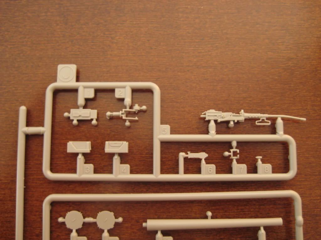
The box is filled to the top with sprues, but the layout of some sprues is a bit awkward.
The M2 is not protected at all, my example came out of the box like this:


The kit provides parts to build three versions of front transmission covers:


I have opted to go for F1, the box art version:

The lower hull needs an extension to be fitted, parts E3/E4, to close the gap over the running gear and the upper hull.

When building the F3 version you are instructed to cut away 1 mm of this extension part to allow it to fit in the recess in the upper hull:
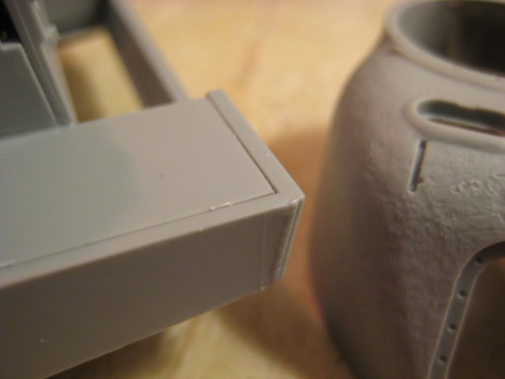
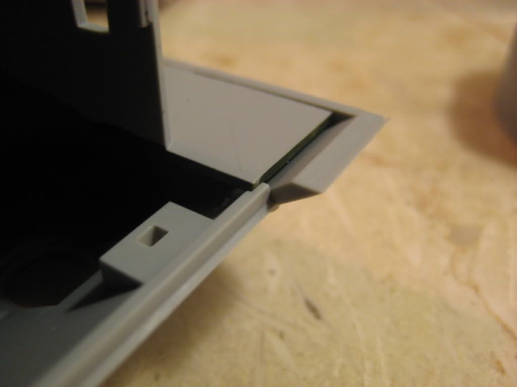


However when building F1 or F2 when you are not supposed to trim these parts the result becomes an overlap in the front of the assembly:
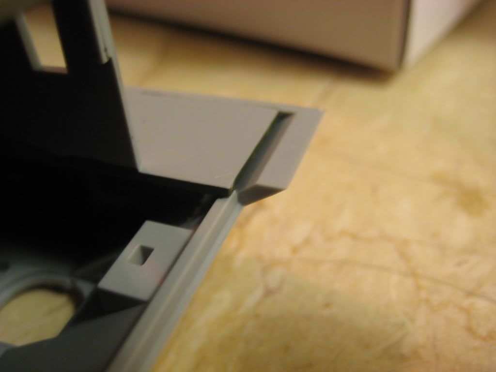


where the lower hull does not correctly fit in the front section resulting in a gap between the transmission cover and the lower hull as such:


You need to cut out the lip in the upper hull to allow the joint, this is not covered in the instructions so take care in this step.


The Turret is very nicely produced with the cast surface looking very convincing.
In the joint between the lower part of the turret (B11) and the upper part (B12) this surface detail is in total absence:
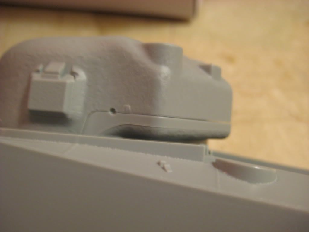


Please provide guidance in this step, is this correct or should I add the cast structure here?

When these issues are sorted I am hoping to make some progress over the weekend and will continue this log on Monday.

With Kind Regards

Utoshita

Deliriant isti Hominem!

  • Member since
    July 2003
  • From: On my kitchen counter top somewhere in central North Carolina.
Posted by disastermaster on Wednesday, August 26, 2009 1:26 PM

http://www.toadmanstankpictures.com/m4huntsville_04.jpg

For more, check HERE.

http://www.innovationbyinstinct.com/services/hosting/clients/accountyp/status/DisasterMaster/%23t1-4.jpg

 https://i.imgur.com/LjRRaV1.png


  • Member since
    July 2004
  • From: Texas
Posted by wbill76 on Wednesday, August 26, 2009 1:50 PM
Utoshita, congrats on taking the plunge and starting your first build log. Will be watching this one with interest.
  • Member since
    July 2007
Posted by Utoshita on Wednesday, August 26, 2009 1:58 PM
Thank you very much for this link disastermaster!
My conclusion is that that the weld seem needs to be there but the area has to be conform with the cast structure.

Thank you very much for your support Bill!

With Kind Regards
Utoshita

Deliriant isti Hominem!

  • Member since
    June 2006
  • From: Netherlands
Posted by Grem56 on Wednesday, August 26, 2009 1:59 PM

Be an interesting build to follow, nice subject.

Julian Smile [:)]


illegal immigrants have always been a problem in the United States. Ask any Indian.....................

Italeri S-100: http://cs.finescale.com/FSMCS/forums/t/112607.aspx?PageIndex=1

Isu-152: http://cs.finescale.com/FSMCS/forums/t/116521.aspx?PageIndex=1


  • Member since
    July 2003
  • From: On my kitchen counter top somewhere in central North Carolina.
Posted by disastermaster on Wednesday, August 26, 2009 2:07 PM

 Utoshita wrote:
Thank you very much for this link disastermaster!
My conclusion is that that the weld seem needs to be there but the area has to be conform with the cast structure.

Thank you very much for your support Bill!

With Kind Regards
Utoshita

You're welcome.

 Here's another one. Check this link for more.http://www.usarmymodels.com/ARTICLES/Sherman%20Corner/Turrets/Turrets%2078461%20Rr.jpg

 http://www.innovationbyinstinct.com/services/hosting/clients/accountyp/status/DisasterMaster/%23t1-4.jpg

 https://i.imgur.com/LjRRaV1.png


  • Member since
    July 2007
Posted by Utoshita on Monday, September 7, 2009 1:56 PM

Progress is fair, the sub assemblies are OK, unfortunately the camera needs an overhaul after being soaked in Vodka.
The turret causes me some headache since the cast structure is not represented in the lower part;

Not sure how to proceed here, current thinking is to sand down the lower part so that it nowhere protrudes the upper part, soak it with liquid glue, dab it with sand paper to give it an appearance of cast structure and move on from there.

With Kind Regards
Utoshita

Deliriant isti Hominem!

  • Member since
    July 2007
Posted by Utoshita on Monday, September 7, 2009 2:03 PM
Actually comparing to DM's linked pictures (thank you very much for this input ) it looks as if the weld seem is the lower demarcation line in Dragons offering, which means that a smoth transition from the top part to the lower part has to be accomplised where Dragon has left us with very poor molding.

Not top quality!

With Kind Regards
Utoshita

Deliriant isti Hominem!

  • Member since
    September 2003
  • From: South Central Wisconsin
Posted by Daywalker on Monday, September 7, 2009 5:00 PM
I will be watching this one!  Good to see how the Dragon kit compares to the Tamiya kit I am working on.  Thumbs Up [tup]

Frank 


  • Member since
    July 2003
  • From: On my kitchen counter top somewhere in central North Carolina.
Posted by disastermaster on Monday, September 7, 2009 7:43 PM

 Utoshita wrote:
................unfortunately the camera needs an overhaul after being soaked in Vodka.
Vodka. Hmmm...., is that a new photography technique?http://i45.photobucket.com/albums/f96/Rijkje/Soaking.gifI currently use the Bud soaking technique myself.

http://www.innovationbyinstinct.com/services/hosting/clients/accountyp/status/DisasterMaster/%23t1-4.jpg

 https://i.imgur.com/LjRRaV1.png


  • Member since
    November 2004
  • From: Essex England
Posted by spacepacker on Tuesday, September 8, 2009 3:15 PM

This kit is my next build, which I will start this Autumn.

So I will be watching your build very closely.

I have the same problem with the distorted M/C gun, but I contacted Dragon and they have supplied a new one. Took a month but I'm not in a hurry...Kenny 

  • Member since
    March 2003
  • From: Nova Scotia,Canada
Posted by VF8PANZER on Tuesday, September 8, 2009 7:24 PM
Some days you're the bug; some days you're the windshield.
  • Member since
    July 2007
Posted by Utoshita on Wednesday, September 9, 2009 1:56 PM

Dear All,

Thank you for your respons and support.

DM, yes a new Photo Technique making the use of filters less important, the picure is sort of faded anyway ;)

VF8PANZER, very good link and exactly what I was hoping for. This will be my way forward.

With Kind Regards
Utoshita

Deliriant isti Hominem!

  • Member since
    July 2006
  • From: New Jersey
Posted by redleg12 on Wednesday, September 9, 2009 7:39 PM

Utoshita - First welcome and don't worry as you can see we don't bite (exect for the Doog.....Shock [:O])

On the turret....you can use Mr. Surfacer to create the cast look on the lower section. It will also be helpful in the seam filling.

Shermans are not my normal area, but you can see the result if you look here as I am using it on my current M40 build which uses the M4 chassis

/forums/1179749/ShowPost.aspx

Hang in there....it only gets better.....remember shaken not stirred

Rounds Complete!!

"The Moral High Ground....A Great Place to Emplace Artillery."

  • Member since
    July 2007
Posted by Utoshita on Sunday, September 13, 2009 9:14 PM
Thank you very much for this redleg12, a very useful link! I am experimenting with deluting Tamiya Putty with alkohol to get to a similar result. Luckely there are so manny "do not use" parts in the box :)
Still think it is pretty poor job by DML, why not include a fancy CAD image showing the area on the box; "Newly designed cast structure... well we did not know what to do here so we left it to you".

With Kind Regards
Utoshita

Deliriant isti Hominem!

  • Member since
    January 2006
You might find this information useful, I've covered some of the...
Posted by Paul Budzik on Monday, September 14, 2009 1:46 PM

Paul

  • Member since
    July 2007
Posted by Utoshita on Tuesday, September 15, 2009 1:28 PM
Paul,
Thank you very much for the link, in a previoes posting VF8PANZER actually pointed me in to your log but I was so occupied with the problems with the missing turret detail that I missed all your other excellent tips and fixes to the same problems that I have encountered in other areas.
Please excuse my ignorance.

Mr. Daywalker, I am not keeping up with you, sh_t happend as it does but I am back on the build on Sunday.

With Kind Regards
Utoshita

Deliriant isti Hominem!

  • Member since
    July 2007
Posted by Utoshita on Tuesday, September 22, 2009 11:30 AM

Dear all,

I have not been able to stick to my timeline lately, life happens sometimes.
But here we go.

Step 1.
Construction starts with the wheel assemblies. These are reasonably straightforward multipart assemblies (6*10 pieces). I opted to attach part V5, a mounting plate to the hull instead of to the road wheel assembly, simply to make alignment of the assemblies to the hull easier in Step 3.

Road wheel assembly, the wheels are actually 2 sided and have a "glue recess" in the center of the outer part. You have the choice between a cast road wheel or a steel stamped.
I have opted for the earlier.


It is difficult to avoid seems where the outer part of the assembly half's V12/13 and V10/11 go together:

Here are the assembled parts after sanding and priming for flaws:


And with the return guide plate in place, look at these "Easy Riders" Cool [8D] :


This is the finished assembly:


The mold seem on the return guide plate is still visible, I will try to fix that before moving on.
DML's drawing shows the road wheels with a prominent mold joint in the middle of the rubber section so I actually decided to leave some of the seem on the rubber. Not sure if that is correct though.

Nest step will be priming the lower sections, I am going to follow Steve "Crockett's" advice and go with a black primer overall.

Thank You for looking, comments are more then welcome.

With Kind Regards
Utoshita

Deliriant isti Hominem!

  • Member since
    July 2007
Posted by Utoshita on Friday, September 25, 2009 12:38 PM

Dear All,
This is my Friday update Tongue [:P]
I decided yesterday to give the road wheel assemblies a black prime coat. The drive bands and the lower hull will get their share to:

I masked off the joints to ensure a strong bond later:

The road wheel assembly after a coat of "Chaos Black"

Not sure if I need filler here, suggestions are welcome?

Following Schnob and Daywalker's progress I realized today that I lost out on the fact that the cast road wheel housing is bidirectional and therefore missing 4 bolt holes for the returns roller arm.
I tried to make a template but I slipped slightly...  

Trying to fix the problem:

The road wheel assemblies are glued to the lower hull. No alignment problems J

Here is the M4 belly up, the last assembly is still waiting for the glue to cure...


Next is the turret, after long grieve I have finally decided to give the bad joint a try.


Thank You for looking, comments are more then welcome.

With Kind Regards
Utoshita

Deliriant isti Hominem!

  • Member since
    July 2007
Posted by Utoshita on Tuesday, September 29, 2009 5:22 PM

Turret Time ;)

The turret detail is very good with nicely depicted cast detail but there is one blemish, the joint between the upper and lower half under the radio compartment.
I want to create a joint between the too parts where I can fill as much as possible and sand off as little as possible.
So i have pushed the lower half as far under the radio compartment as i could.
The result is OK at the far back and on the left hand side, but on the right hand side the lower part protrudes the upper half.

I masked off the lower part and tried to flush the area with a thin coat of Tamiya putty:

I am going to allow the putty to cure for a day or so.
I will then try to sand off as little as possible with the aim to create a surface that can be detailed with liquid cement / a surface primer and a stubbed brush.
Now that the putty is on I have decided to be optimistic about it Whistling [:-^]

I decided to fix the problem with the overlap between upper and lower hull by taking out part of the lip in the upper hull.

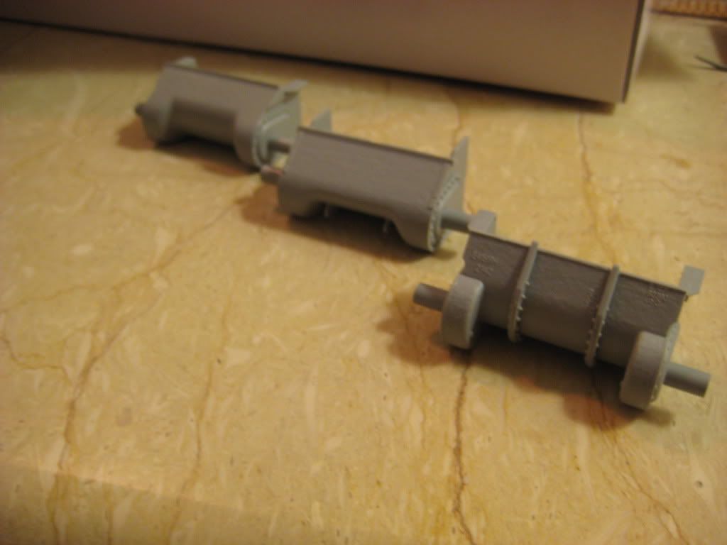
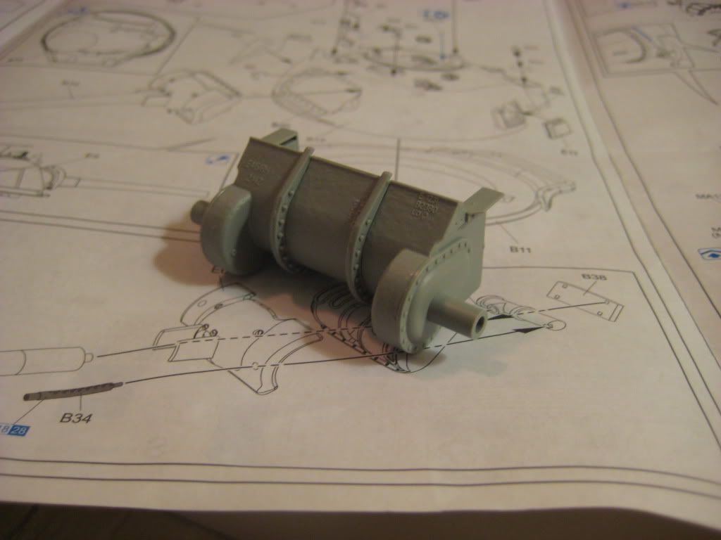
The air cleaners need a bit of attention, in each of the assemblies you get too molded on tigtening bolts and too that need to be fitted. The logic is easy; the molded on ones go into the invisible corners and the fitted ones on the visible sides:

Thank You for looking, comments are more then welcome.

With Kind Regards
Utoshita

Edit 2009-09-29:
It becomes obvioues to me when I look at my pictures that the issues that I am trying to adress needs to be pointed out in a better way, I will try to do that until tomorrow.
Stop Edit.

Deliriant isti Hominem!

  • Member since
    January 2009
  • From: Everett, WA
Posted by Schnobs on Wednesday, September 30, 2009 3:38 AM

Looking good Utoshita!

Nice detail work!

"There is a principle which is a bar against all information, which is proof against all arguments and which cannot fail to keep a man in everlasting ignorance. That principle is contempt prior to investigation." Herbert Spencer
  • Member since
    February 2009
  • From: mass,USA
Posted by scratchmod on Wednesday, September 30, 2009 5:23 AM

Your Sherman is looking good so far, a very nice clean build. The pics are all great as is the blog.


Rob

  • Member since
    January 2008
  • From: Bournemouth UK
Posted by Bodge on Wednesday, September 30, 2009 6:36 AM
Nice workThumbs Up [tup]
  • Member since
    September 2003
  • From: South Central Wisconsin
Posted by Daywalker on Wednesday, September 30, 2009 6:38 AM
Yes, this is very good work!  Great to see so many Shermans about.  Looking forward to more of your progress pics. Thumbs Up [tup]

Frank 


  • Member since
    July 2007
Posted by Utoshita on Friday, October 2, 2009 11:45 AM
Thank you for your kind comments, I allways look forward to your support and critical comments Smile [:)]
I hope to be able to bend some Photo Etched tomorrow and the turret is going to be completed as well.

With Kind Regards
Utoshita

Deliriant isti Hominem!

  • Member since
    July 2006
  • From: New Jersey
Posted by redleg12 on Friday, October 2, 2009 7:01 PM

Very nice progress to date. Yep life can get in the way but it appears you are marching on.

Rounds Complete!!

"The Moral High Ground....A Great Place to Emplace Artillery."

  • Member since
    June 2009
Posted by Guney on Saturday, October 3, 2009 4:50 PM
Good works...Good luck..:)
  • Member since
    July 2007
Posted by Utoshita on Tuesday, October 20, 2009 9:18 AM

Thank You for your kind remarks Redleg12 and Guney.
I am marching on all right, just not very straight ;)

Back to the turret;

After removing the tape I sanded down the putty to sit flush with the pre-cast detail.
I then painted the lower section with Mr. Surfacer and stippled it with a short brush to simulate cast detail.

Here is the turrets lower left:


The turrets lower right:


The holes intended to position the lifting hooks where lost in the process due to a lack of attention from my side. I took out the pin vise and Eye balled the new position.
I think I got it reasonably right.
The mold seems will be sanded now that they are in position:

Moving on to the turret periscopes and their guard ‘nests' (G14), the instructions want you to drill four holes in the circular part holding the periscope (G6). These are for tiny positioning ‘dots' on the guard nests. I decided not to assuming that the cement glue is going to melt those anyway.


Care is required in this step, the guard ‘nests' are extremely fragile. Use a sharp knife instead of a sprue cutter, the sprue cutter always compresses the parts and this might be just enough to snap the parts.

The periscope itself is a clear plastic part that I have left of for now; they will not be installed until after painting.

The rest of the turret detail is left off until I have moved the kit, don't want to break things off unnecessarily.

It is not about the goal, it is all about the journey Whistling [:-^]

With Kind Regards
Utoshita  

Deliriant isti Hominem!

  • Member since
    May 2005
  • From: Eugene, Oregon
Posted by hughes2682 on Tuesday, October 20, 2009 6:59 PM
Utoshita,
Nicely done work on the turret there! I am looking forward to following the progress of this build. Thank you for the postings
Cheers
Dave

http://img.photobucket.com/albums/v317/Aaronw/Groupbuilds/ClassicAviationGB2010bomb.jpg

With enough thrust, pigs fly just fine.

  • Member since
    July 2007
Posted by Utoshita on Wednesday, October 21, 2009 1:02 AM

Thanks Dave, very much appreciated!

Unfortunately I have to report 2 setbacks today:
Number 1: The Commanders periscope guard did not survive the transport:

There are 2 extra guard 'Nests' on sprue A (15) but these do not fit Black Eye [B)]
Happy for advice here, leave off, get aftermarket, talk to Dragon?
I think I will start with Dragon, the M2 needs replacement anyway.

Number 2: This is embarrassing, I managed to mix up the air intakes parts F4(F3).

Mayor surgery is now required. Will be tricky to get this 100% right, it is likely that they land up with some gear stowed up against them...a reminder not to mix Cuba Libre and 1/35 kits Dead [xx(]
With Kind Regards
Utoshita

Deliriant isti Hominem!

JOIN OUR COMMUNITY!

Our community is FREE to join. To participate you must either login or register for an account.

SEARCH FORUMS
FREE NEWSLETTER
By signing up you may also receive reader surveys and occasional special offers. We do not sell, rent or trade our email lists. View our Privacy Policy.