SEARCH FINESCALE.COM

Enter keywords or a search phrase below:

Monogram/Revell "Yankee Lady" Enhanced Build

7430 views
94 replies
1 rating 2 rating 3 rating 4 rating 5 rating
  • Member since
    March 2012
  • From: Louisville, KY
Posted by Builder 2010 on Saturday, August 27, 2016 9:23 PM

Thanks! My #1 grandson wanted to work on one of his WIP models in the basement. He's building the Trumpeter USS Hornet. I had run a model clinic for him and his friends about 6 years ago and was given a bunch of really nice plastic kits by one of the parents. Included was this carrier model, plus the Trumpeter Essex, and a Trumpeter 1/32 TBM-3 Avenger. He just want to build the Hornet OOB to have some fun. He's not super-detailing it. The Essex, however, is going to get the Missouri treatment with all the bells and whistles. I'm champing at the bitt to build that Avenger and ordered Eduard upgrade parts for it. I'm also building a 39' X 15' O'gauge model railroad so I'm a very busy retired person.

While he was in the shop I did a little work on the 17, and got all four engines connected to all four cowls. He helped me CA the first cowl flap ring to the engine. I held it still with the lugs on both the engine and ring in contact while he applied the CA. It actually held better than I expected so I glued on the cowl to the ring also with CA (it's resin, so no solvent cement). I then found that I could put a dot of medium CA on each tab and then very gingerly place the engine on them. When it set, I went back and added some more CA from behind. This worked and I didn't need two people involved. There are three different types of cowl rings. The two outer engines share the same rings with the bulge at the bottom to accommodate the exhaust header running to the turbo. But the inner engines each have their own ring since the clearance is now at the side for the pipe that exits the engines and runs down the side around the wheel well and then turns inward to tie into the turbo inlet. You need to keep the closed flap position at TDC. When installing on the plane you need to keep this straight.

All four engines are now away for safe keeping until I'm ready to paint the aircraft. I then started working on the PE bomb bay doors. I annealed all the PE. In retrospect, it might not have been such a good idea since it makes it very pliable, almost too pliable. You have to pre-shape the doors on the plastic model's bomb bay before cutting them out of the model. You then have to glue 6 reinforcing ribs to the insides. These have to follow the door's contours. I'm planning on having the bomb bay open so this detail will be seen. Pictures will follow next session. I again scraped all primer from any area to receive CA. I actually toyed with the idea of soldering these parts on, but couldn't conceive of a good way to hold them still. I have an American Beauty Resistance Soldering Unit which can do some amazing small soldering jobs, but this might be too small even for it. I may give it a try since using the CA was sub-par. If soldered, it would never come apart.

  • Member since
    March 2012
  • From: Louisville, KY
Posted by Builder 2010 on Saturday, August 27, 2016 10:19 PM

Speaking of the Missouri, I posted some pics of this four years ago, but wanted to re-post for those that missed it. It's the 1:350 Tamiya kit which I had first built before the age of the aftermarket details, and then re-bought it in 2011 to work on while grandson 1 built models in my workshop. This time I wanted to totally blow it out. I did so with Scale Decks laser-cut wood decks, Eduard PE, Aber 16" guns, brass props, steel prop shafts, hand built brass masting, some scratch-build parts including running lights, whale boat winch, aft flag bags. Drilled out and glazed searchlights, and all overhanging decks received proper stanchions to hold them up. The build took 13 months.

The boat depicts the "Big Mo" between the signing of the surrender in Tokyo Bay in Sept. 1945 and leaving Pearl for NYC Harbor in Oct of the same year. During this time, the deck blue paint was holy stoned back to original teak, and the 20mm gun tubs were removed flanking #2 turret. I had Scale Decks blank that area so I could leave those guns off. It was also a time when all the other late WWII equipment was present including the big search radar dish. I wanted to show off the teak decks and this was the only point in time when all those above conditions were met.

I suppose these pics should be on the boat forum so maybe I'll post them there... or maybe not.

This close up shows a lot of the little stuff like those added stanchions. You can't see it here, but even the radio antenna bushings are modeled after pictures I found of them. The model's originals were just little nubs.

Radio rigging and flag halyards are fine E-Z Line. I wouldn't use anything else for this. I tried stretched sprue and it was a disaster. E-Z Line bonds instantly with thin CA so making those line-to-line connections are a piece of cake to not only make an invisible joint, but also applying sufficient tension as would be seen on the real thing. Prop shafts are white because that's there real color, as seen in this pic with *** Langraff, the Long Beach Superintendent standing on Missouri's prop strut. It's a white lead anti-fouling compound.

Next post willl be back to the B-17G


  • Member since
    March 2012
  • From: Louisville, KY
Posted by Builder 2010 on Monday, August 29, 2016 5:43 PM

Back to the B-17. I cobbled together the Verlinden PE bomb bay doors. I decided against trying to solder on these little ribs and wrestled with CA. The results are so-so. I don't like gluing metal to metal with CA when the edge I'm gluing is less than 0.010". I'm hoping that paint will hide some of the uglyness. 

The front crew door is also in the Verlinden set. It too will have some parts CA'd to it. Both of these will be very delicate regarding holding them onto the model. I suspect, I'm install them very late in the construction; possibly after the decals go on since you need to handle the model a lot during that process.

  • Member since
    December 2010
  • From: Salem, Oregon
Posted by 1943Mike on Monday, August 29, 2016 11:01 PM

Fine work on the Mighty Mo.

Although I do use EZ Line for all my 1/350 WWI & WWII ship rigging, I still find I have to be careful about the proper tension so as not to have the lines sag too much. You've gotten the rigging just right.

Following along with interest on the 17 build.

Mike

"Le temps est un grand maître, mais malheureusement, il tue tous ses élèves."

Hector Berlioz

  • Member since
    December 2002
  • From: Northern California
Posted by jeaton01 on Wednesday, August 31, 2016 10:57 PM

Builder, that's not a belt on the prop governor, it's a cable which rotates the pulley.  The cable is locked in postion on the pulley, the other end of the cable circuit is the throttle quadrant, of course.

John

To see build logs for my models:  http://goldeneramodel.com/mymodels/mymodels.html


  • Member since
    March 2012
  • From: Louisville, KY
Posted by Builder 2010 on Sunday, September 4, 2016 5:41 PM

First of all, thanks for all the nice comments and especially on the Mo. 

E-Z Line would have worked also for just a push-pull connection to the top of the pulley. Eduard had the PE wrapping the pulley and belaying in those indentations on the baffle.

These will not be really visible unless someone picks up the model and peers into those cowls. I don't believe anyone should do that. I will probably mount the model on a scenicked base since it will be easier to transport in one piece from L'ville to Philly. I'm worried about the Bomb Bay and Crew's Door being held open by some flimsy PE "hinges".

  • Member since
    May 2016
Posted by Revenant on Sunday, September 4, 2016 6:02 PM

Looking good...

  • Member since
    March 2012
  • From: Louisville, KY
Posted by Builder 2010 on Tuesday, September 6, 2016 10:44 AM

Thank You!

My grandson's been building the very fine Hasegawa F-22 (1:48) kit for several years. He bogged down on the decals. He likes building, he hates decals. I happen to really like decals and as a kid I used to buy kits based on how many decals they had. Finally he asked me to finish it up. He's in 10th grade and doesn't get much model-building time these days. I got all the decals done and decided to paint the canopy. The kit had two; a clear and a smoked version. I started with the smoked version. First I tried using Parafilm M, but it wasn't working as it should (probably since I don't know how to use it properly), then I thought of Press-n-Seal. 

This post is about the results of that test. 

The Press-n-Seal (hereafter known as PnS) leaves gooey residue behind on styrene. It was a mess. And it leaked. I attempted to removed the PnS residue with alcohol and it didn't get it off. Then I used Goo Gone which removed the sticky stuff and also attacked the paint. To make matters worse, I had hand brushed the light grey paint and I had touched it before it was completely dry. This pulled some up and made more of a mess.

I turned to the clear canopy. This time I went with my tried and true Tamiya masking tape and air brush. The results are dramatically different as seen here.

The picture shows some of the residue after I already tried to remove some. When I saw what my methods were doing to the paint, I realized that my efforts were useless. I could remove all of it and start over. If the clear canopy hadn't come out so good, I might have done that. There was no leakage with the Tamiya tape. It was able to bend successfully around the shallow curve at the bottom. Even where the tape overlapped at the end points, there was no leakage.

Verdict: PnS doesn't work well in this application. Stick with Tamiya masking tape.

  • Member since
    July 2016
  • From: Malvern, PA
Posted by WillysMB on Tuesday, September 6, 2016 11:55 AM

Fabulous work! Spent a very pleasant 6 mos of my life a number of years ago working on the National Warplane Museums B-17 "Fuddy Duddy." I'm guessing your son took his ride on Yankee Lady at WWII Weekend in Reading where she's always one of the main attractions along with FIFI and Diamond Lil (CAF's B-29 and B-24). WWII Weekend is now the largest WWII event in the country with aircraft, vehicles, and over 60 reenacting groups.

  • Member since
    March 2012
  • From: Louisville, KY
Posted by Builder 2010 on Tuesday, September 6, 2016 6:28 PM

Thank you. I need to correct your impression. The B-17 plane is not for my son, but for a boy (now 50) who spent time in the summers watching me build models in my garage in the late 70s and early 80s. He grew up liking modeling and getting the "Yankee Lady" ride was on his bucket list.

A couple more notes on the F-22. I finished the model today for my grandson. The model had been sitting around so long that some parts were missing, one being the port inner gear door. Also missing were some of the little door hinges to hold the nose gear doors. For them, I just glued the doors to the airframe directly and you really can't see that inner main gear door position unless you really try.

After gluing all the stuff on except for the canopy, I took it outside and gave it a shot of Dullcoat. I forgot to mask the HUD so it's no longer clear. The front landing gear, like real USAF modern fighters, is very fragile and can barely support the plane's weight. It should probably be die cast. It's one reason why I'm a big fan of 1:32 scale. Speaking of 1:32, boy, would I like to see an F-35B in that scale.

Next, I'll be back on the 17.

  • Member since
    March 2012
  • From: Louisville, KY
Posted by Builder 2010 on Wednesday, September 7, 2016 8:58 PM

This is actually the 3rd time I've started writing this post. Each time I accidentally closed the window when I was jumping back and forth between photobucket and this site to get the pictures and hitting that "X" instead of the middle of the tab and...Poof!...lost again. Let me see if the 3rd time's a charm.

Back to the B-17...

Started with the foreward crew door. This is pre-formed to the fuselage's curve after cutting it from the fret. I didn't like the way the PE door handle was attached so I drilled it to accept an 0.021" brass wire which is CA'd to both. Much more secure. The go on two folded PE hinges. I scraped off the primer so they would hold better.

I had to remove the plastic door and did this by the multi-hole method. I started with pin pricks using a divider, than an 0.032" drill followed by a #52. This insured that I wouldn't deviate and drill holes outside of the lines.

After removing the webs with a #11 blade, I used various files and sanding sticks to clean up the edges. I also thinned it back from the edge to made the fuselage appear less fat. I trial fit the door into the opening and it will work nicely.

I'll paint the inner door with interior greena and the exterior will be natual metal. Since I'm not painting the fuselage I put this little door in the box with the engines and bomb bay doors.

I then started on the resin main gears. These are multi-part affairs with lots of good details. The axles are separate resin parts that fit into a hole on the main strut and, like all the resin parts which follow, are CA'd in place. CA loves resin and vice versa. Added to this is a boss on the non-oleo portion of the strut to provide the upper hinge point for the scissiors link. I had to file a circular groove in the struct so this part had some surface area upon which to adhere. Then came the scissors links. These had resin webs between them. When I attempted to cut one away, the link broke off. I was able to CA it back on. The when installing the other one, again the link broke, but this time hit the floor and into the void. I made a replacement out of styrene and CA'd it to the assembly. It worked. There's no load on these parts so as long as you don't bump it, it will hold up okay. I'd love to do this out of brass and solder the whole deal.

Lastly, here's a comparison with the kit's clunky styrene and the Verlinden replacements.

The styrene locking link gets removed from the kit strut and is attached to the resin ones. This joint too could be suspect and I may reinforce it also with some very fine guitar string piano wire. Drilling 0.021" will remove too much material and leave a very weak structure, but a 0.010" piece of piano wire will do the trick. That will be up next. The molded on brake tank thingy is also a separate resin part to which goes some copper magnet wire that will serve as brake lines. It will look very nice when finished and painted.

  • Member since
    March 2015
  • From: Streetsboro, Ohio
Posted by Toshi on Wednesday, September 7, 2016 10:36 PM

I can't stop saying to myself how impressive your work is.  Did you start your build on the Trumpeter TBF Avenger yet?  I built that last year.  It's one huge kit!  I'd love to see a WIP if you have the time.  As always, what a fantastic job you are doing!

Toshi

On The Bench: Revell 1/48 B-25 Mitchell


Married to the most caring, loving, understanding, and beautiful wife in the world.  Mrs. Toshi


  • Member since
    March 2012
  • From: Louisville, KY
Posted by Builder 2010 on Friday, September 9, 2016 5:57 PM

Thank you, but looks can be deceiving. I make my share of errors, often because I don't study the planes to enough depth. The TBM is on the shelf and will be there for a little while. I have to finish that huge mountain on my model RR since I can't run any trains until it's finished. After that there's a structure or two needing building and then I'll get into the TBM. My grandson wants a crack at it so it may happen sooner rather than later.

Today, I got into the bombadier compartment. Lots of little resin bits that replace molded on details. There was some ambiguity on the Verlinden plans that I needed to decipher. The part that caused me the most angst was that control stand in front of the Norden Bombsight. You were supposed to clip the top off the kit part and then glue the more detailed head and then you have to attach the two handgrips. Those handgrips really gave me fits. The first one went on okay. The second flew out of the tweezers and disappeard, so I scratchbuilt another and glued it on. Then when handling the whole assembly when working on the back bulkhead, the first one broke off with the little stem and hit the floor. After rolling my work table back further, and using a dust brush to sweep the area, both handgrips showed up. It then broke off again. This time I have no idea where it is and I'll have to figure how to get the other that I found into place. I would have just used the kit's piece, but I had already disassembled it so I could use its mounting shaft. There was no good way to get the mounting shaft attached to the resin head so I made my own shaft out of 0.032" brass. When this picture was taken, both handgrips were in place.

To remove all the molded on detail I used a combination of razor saw, #11 blade, a special chisel sold by MicroMart for doing just this, and various files and sanding tools.

I added the work table and then added the navigotor's seat. On this table was supposed to go the big switch panel, but the plans showed it up against the bulkhead. It doesn't fit, so I glued it to the table in front of the bulkhead. I also removed molded on pipes and conduits and replaced them with brass. Very little of this stuff is going to show up, even through the big front window. There will be too much optical distortion for any fine details to reall show up, but it's fun to do.

I've got one more ammo box to install on the bulkhead and this piece will be ready for painting and detailing. Because of the all the CA'ing, I couldn't decide if I should air brush the zinc chromate and interior green before adding all the bits or after. I chose to paint after since it will hide a bunch of glue blemishes. I'm good with fine detail painting and enjoy it so it will work out okay. I have to remove some details on the fuselage sides to replace with resin so that will be next and then I'm move to the flight deck.

  • Member since
    August 2013
Posted by Jay Jay on Saturday, September 10, 2016 7:07 AM

This is such a good WIP I feel like I'm in an advanced how-to modeling class. 

Do i get college credits for following along ?  Wink

TY so much for posting all this, I'm learning much Bro.


 I'm finally retired. Now time I got, money I don't.

  • Member since
    March 2003
Posted by rangerj on Saturday, September 10, 2016 11:15 AM

When I go to Hawii to pay respects to a cousin who was on the USS Arizona on Dec. 7, 1941 and was one of the 1177 who went down with her that day, I also visit the USS MO. I would encourage anyone who gets the chance to go to Hawii to do that.

The Yankee Lady is at the Willow Run Airport in Yipsilanti MI whic is about 1/2 way betweenn Detroit and Ann Arbor MI. The historic preservation group there also has a flying B-25 you can get a ride in. Book your reservation way in advance. They also have a huge airshow every year call Thunder Over MI. It was August 21-22 this year and featured the Blue Angles.

Of historic note the Willow Run airport was built by Henrey Ford and he built a manufacturing plant to build B-24s for the war effort (WWII). He produced more B-24s that the other three plants building B-24s put together. After the war he gave the airport and facilities to the local government. The group is in the process of getting a Ford built B-24 for display at the Museum.

I am working on the same kit but I am converting it to a B-17H with the Higgens rescue boat. I like your improvements and I will "borrow" them.


  • Member since
    March 2012
  • From: Louisville, KY
Posted by Builder 2010 on Wednesday, September 14, 2016 8:16 PM

I've been to see the New Jersey 3 times so seeing the Missouri would seem redundant. That being said, I'd sure like to somehow get the one I built to that ship. We're planning our first Hawii trip next year, but it won't include schlepping a 40" model (with case) to Pearl Harbor. 

I didn't get much done the last couple of days. We're heading to Spain for a vacation starting on Friday and had stuff to do regarding that. I did get the bombardier's compartment all fitted out, added a couple of O2 bottles in the fuselage, and installed the cockpit side panels. I also added a couple of piece of PE on the front side windows. I was surprised that the 3-window frame was included on the fret for the right side, but not the left, and yet "Yankee Lady" has the 3-window partitiion on both sides. I'm going to add some PE stripping to the other side. It will lack the cute little rivets.

I exchanged the O2 bottle next to the entry door with the fire extinguisher casting as it should be. After checking photos I realized my error and made the switch. Becuase CA doesn't weld resin to styrene, you can break it away pretty cleanly. I was concerned that the upper-left ammo box would interfere with the fuselage, but after checking, it works okay. This assembly's ready for some paint.

Here are all the little details on the right side of which I spoke. In an ideal world, I would have replaced those molded on oxygen hoses with an "A" or "D" round-wound guitar string, but it will not be seen very well and, more importantly, the only round-wound strings I have are sitting on my Stratocaster and aren't coming off for this model.

There is a piece of PE trim on the fore side of the next window. It fit the left side well, but didn't fit the right side very well at all. With the glazing in place it will work okay... I hope.

While I may get some work done tomorrow, but don't count on it. So if I don't put in a journal entry for a little over a week, you'll all know why.

  • Member since
    August 2016
Posted by Keyda81 on Wednesday, September 14, 2016 9:21 PM

That is so me having little parts going flying out of the tweezers.  I've lost more than one pitot tube that way, lol.  I snapped them of my 1/48 C-130 at least 3 times.  I always forget about them when moving the model around.

Looking forward to seeing this come together, have a nice vacation! 

  • Member since
    January 2015
  • From: Tumwater, WA.
Posted by M. Brindos on Wednesday, September 14, 2016 9:42 PM

lol Keyda! We have all had that issue! Try replacing those Pitot tubes with brass wire and then they stab you when you forget about them lol!

---------------------------------

Have a great Vacation! I know we will all be looking forward to your next update. You've been keeping me entranced at least, lol.

- Mike Brindos "Lost Boy"

  • Member since
    March 2012
  • From: Louisville, KY
Posted by Builder 2010 on Thursday, September 15, 2016 10:12 PM

Thanks guys! I did get some shop time today. I was able to open up the bomb bay doors since the PE ones will be there. And then I got the first color in place; interior green. This will have a nice long 10 days to dry before I start detail painting. I used a small drill and did the row-of-holes method on the hinge line, but was able to use the razor saw for the perpendicular cuts. After filing down to the seam line, it was done.

I'm using Model Master acrylics for the interior green. I thinned it a bit with Testors universal acrylic thinner. I use a Badger 150 gun that's about 40 years old. Badger's have a lifetime warranty. This was borne out when I sent it away a few years ago and they completely rebuit it with new bushings, nozzle and needle for just the price of shipping.

I sprayed all the parts that needed this color on their trees. I'm going to enjoy picking out all the details. 

So until I return, hasta luego.

I'm actually trying to learn Spanish using Duolinguo. It's a very user friendly language training program that syncs between the computer and the smart phone. My grandkids have used it their early language training.

  • Member since
    August 2013
Posted by Jay Jay on Friday, September 16, 2016 8:57 AM

I really like the interior color . I usually mix my own Tamiya interior green but it comes out near the color of your MM and yours is easier. looking good Bro.

I recently sent in My old Badger 200 but it cost me $31.00...cheap but not free like yours. It does work like new however.


 I'm finally retired. Now time I got, money I don't.

  • Member since
    March 2012
  • From: Louisville, KY
Posted by Builder 2010 on Monday, October 3, 2016 5:02 PM

Well... Thanks! It's been 17 days since the last post taken up by working on a monster mountain for my O'gauge RR, and a really nice 10-day trip to Spain. Then last week while working on said mountain and attempting to use a staple gun at an odd angle, I heard and felt a "pop" in my shoulder. It went downhill from there. I apparently did something to my bicep tendon, although this was an external exam by my orthopedic surgeon son in law. I may have pulled the tendon out of the groove in which it runs or I could have torn something. Anyway, I have to take it easy with my right hand so... building models is the perfect activity.

Today I got the interior of the fuze painted, painted the wheels, and finish painting the bombardier compartment and started painting the props. 

The only unconventional part of the bombardier painting was the plywood work table. I used a first coat of Tamiya Nato Brown and then a top coat of a Nato Brown and Flat Yellow mix. When it was dry I wet-sanded with a fine grit stick and removed the yellow top coat exposing the brown that was sitting on the raised plastic wood grain. It all doesn't matter since the top surface of this table (along with almost everything else inside) is not visible when the fuze is closed and all the plastic glazing is in place.

I painted all the switches and dials randomly since I have no idea what is actually going on with this apparatus.

I then worked on the main wheels. I first airbrushed Valllejo acrylic metal finish for the hubs. Then I made circular masks for the hubs to paint Tamiya Rubber Black. It's a new color that's got just a little gray to it and looks very good. To make the circular masks I measured the diameter with my digital caliper and came up with .560". I divided this in half to the radius and set this number on the caliper and locked it. I have a Starrett divider that I sharpened on edge to a razor-sharp chisel point and then cut the circles out of .75" Tamiya Masking Tape. I had to do a little touch up after it was all done.

While I had the silver acrylic out I wanted to paint the tail portion of the fuze which apparently natural metal instead of interior green. I masked the demarcation line and then used some packing paper to finish out the mask so the rest of the interior didn't get over-sprayed. I found this paint hard to clean out of the airbrush and had to disassemble it all to get it unclogged.

After this dried I painted the O2 bottles yellow. Also in this picture you can see all the detail painting for the walls and flight deck side walls.

Lastly, I also sprayed the prop hubs and then removed them from the sprues. After cleaning up flash and only on one blade, I brush painted the Rubber Black. I realized that I wanted to do the yellow ends first and then mask them so I did this on the other three props and hand-brushed the tips. For the rest I brush painted the yellow over the lines and then tomorrow will mask and paint the black. I'm not airbrushing these since the masking around the hubs is to tricky to be worth the effort.

I also hand brushed the tailwheel aluminum after air brushing the rubber black.

  • Member since
    August 2016
  • From: Eufaula, Alabama
Posted by WannabeFarmboy on Monday, October 3, 2016 6:14 PM

Absolutely incredible work. 

  • Member since
    March 2012
  • From: Louisville, KY
Posted by Builder 2010 on Tuesday, October 4, 2016 7:41 PM

Thank you!

Even though the shoulder is beginning to function a little better, I worked only on the bomber today. The fellow for whom I'm building it is going to visit me in Louisville in the beginning of November, but we're going to be back East the week before Halloween, which means I can bring the bomber to him at that time. So that gives me a firm date to finish it, October 19. I'm making good progress and should have it done by then.

Today, I masked and painted that finicky little ball turret. I wasn't sure what parts were glazed and what aluminum so I went to the Internet and downloaded a good picture of one. I'm still waiting for m Eduard B-17 masks and suspect that I'll have the model finished by the time they arrive. I did the masking with Tamiya narrow tape and some Scotch Magic Tape.

To do this I put the tape in place, burnish it down paying attention to pushing into the engraved frame lines and then with a very sharp #11 blade. For the little windows down the flank, the engraving was so shallow that I couldn't find it using Tamiya tape so I switched to Magic tape so I could see the lines through it.

I stuck the halves onto a wide blue masking tape after sealing the little halve holes with some more tape. Then I sprayed it with Tamiya Rattle Can Spray Natural Metal. It's a lacquer, looks good with fine grain, and dries really fast.

I was very pleased with the result when I pulled the tape. There was no bleed through anywhere which was, frankly, unexpected.

I built a gun set using the Verlinden 50 cal replacements. Unfortunately, they did not have a set specifically for the ball turret. The kit's version has the guns tied together with some form of mechanism to properly space the guns so they fit through the apertures in the turrett. I had to cobble a spacer together out of scrap resin sprue after transferring the distance with the digital calipers. Incidentally, I use digital calipers more often to transfer measurements than to actually get a digital reading.

The Verlinden barrels are much finer than the massive kit version. They are also much more delicate. When I built that 1/16 scale RC version I had to scratch-build all the guns since all that was included was some wood dowels. I machined the barrels out of two layers of aluminum: inner solid rod drilled with the 1/16 of a 50 cal. bore and an outer jacket drilled with the cooling holes. Ideally, that outer jacket should have been photo-etched (which I can't do...yet). I made the receivers from styrene. The Royal kit's vacuum formed ball turrett was actually a terrible rendition, but at least the guns were cool. I even had to build out the bolsters where the barrels exit the turrett. I used epoxy putty for that.

I finished painting the props and then over-coated the front side with Tamiya clear gloss spray as a surface for the "Hamilton Standard" decals that go on each blade.

I finished building up the flight deck with the addition of control sticks, seats and rear bulkhead. I didn't bother to paint the seat support frames since they're be invisible.

Lastly, I put together the radio room. Again, due to its invisibilty didn't detail any of it other than attaching the seat. There is a skylight on top, but the plastic is not optically pure and will distort anything underneath.

I test fit the fuselage sides and amazingly, it all fits. There's some more surgery needed. The Verlinder windscreen is a photo-etched frame assembly with acetate windows which will be optically clear. The Cheyene tail gunner's house is also PE with glazing. Both it and the upgraded tail turret need plastic removed from that area. I'm going to work on that next since you can't do surgery when the model is all painted and pretty.

  • Member since
    August 2016
  • From: Eufaula, Alabama
Posted by WannabeFarmboy on Wednesday, October 5, 2016 5:18 AM

This is just absolutely fantastic work! Every time I see work like this, I feel inspired to spend that little bit of extra time on a seam or masking (etc.) in hopes of stepping up my game to go from building decent toys to super detailed miniatures of the real thing. 

  • Member since
    February 2006
  • From: Boston
Posted by Wilbur Wright on Wednesday, October 5, 2016 12:18 PM

Very nice work. You've got to have stamina to get into the details like that. My model stamina is slowly waning with my eyesight.


It's nice that you have your grandson building models.  I don't know any kids these days that do.  100% of my LHS's customers are adults and destination customers.


  • Member since
    March 2012
  • From: Louisville, KY
Posted by Builder 2010 on Wednesday, October 5, 2016 6:29 PM

Thanks Guys! I appreciate the input and am glad that I'm inspiring older folks as well as young ones. I ran a Model Building Workshop in 2010 and 11 for junior high kids. It was instigated by a single mom whose son was a model builder who she couldn't help. A few of the kids went on to continue building. In some cases there were those that really shouldn't be working with sharp objects. My grandson continued building.

Today was a potpourri of things starting with finishing up the propellors by adding the "Hamilton Standard" labeling to each blade. I mounted the prop on a shaved end of a micro-brush and held that in the PanaVise. After the decals dried I shot them with Dulcoat to level it all out.

Here are all four done and waiting to be mounted on those spiffy R-1820s.

Next up was finishing up the ball turrett. After painting the guns Tamiya gunmetal, I CA'd the guns into the front ball half. I clamped both halves together and applied solvent cement with my Touch-n-flo capillary applicator. After it dried I sprayed a bit of the Tamiya Bare Metal into a cup and touched up any glue marks. I then build the suspension hanger, sprayed it with the same color and snapped the ball into the hanger and then hanger into the radio compartment floor. This is a very old model with very old molds and there was lots of flash and ejection pin marks on parts. 

With the simple stuff out of the way it was time to get into the two main challenges. The first was the Cheyenne tail gunner's compartment and gun emplacement. This Verlinden change required some mods to the fuselage, one of which was to remove the boss that held the B-17E style tail gun so the Verlinder updated gun can be mounted flush to the tail. The other was to both open up the space a bit AND to remove the rear-most 1/8" of the compartment opening for the PE gun sight that will be added a bit later.

Then it was time to tackle the PE tail gunner's windows. The first part had to be folded and bent to fit the fuze's contours. The second part was the rear window that needed bending to a nice curve that had to match the first parts width. Before bending they ask that you cut the acetate glazing. I had forgotten to do this for the main part, but was able to cut the odd-shaped rounded window. I CA'd the glazing in place before curving the piece by wrapping it around a suitable diameter. For the main part glazing I was able to measure and cut the acetate with the part in its formed shaped. I had to adjust the fuze opening a few more times once all the forming was done.

The second challenge: the new flight deck window set. First of all, this stuff is really cool since it allows for an open left side seat's window. And it's also tough since the plastic fuze's opening does not fit this PE and needs to be shaved and re-shaped.

I've been suffering a bit with the very soft PE which is a self-inflicted wound. I was so traumatized by the Eduard PE hardness when building the Missouri that I annealed all this before using it. The annealing was too effective and the PE bends like modeling clay. As I was handling the parts during the fitting and glazing it kept deforming and I would have to flatten in my PE bending jig over and over. Next time, I'll hold off annealing until I find out how brittle the metal is.

In this picture you'll see that some more fitting is probably warranted. The acetate is so myuch more optically clear than the styrene kit windows. In this case I measured all the acetate while the PE was flat.

Finally, a couple of new pliers I ordered from MicroMark arrived today. They're parallel jaw pliers which I wanted for some time. Traditional long-nose pliers when grabbing and oject often only hold by one point since the tapered jaws create a tapered opening. For bending stuff where I need even grip I was resorting to using my vise grips. This way is much more elegant. One pair with the straight jaws is brass-lined to be a little easier on surfaces. The other is a loop-forming tool that will also do the job with parallel pressure.

Tomorrow I'll continue with fitting the windows. Once done, it will time to start enclsoing the fuselage, building wings and starting the painting and finishing process.

  • Member since
    March 2012
  • From: Louisville, KY
Posted by Builder 2010 on Friday, October 7, 2016 5:31 PM
Thursday was spent entirely installing the flight deck PE windows. It was difficult, frustrating and the results didn't not meet my level of expectations. The problem was that I kept getting CA on the acetate windows. I had to keep handling the assemblies to get the fit just right and this handling increased the deformation I was having and offered more opportunites to screw up the acetate. I replaced the windows and this too created problems especially when I had to replace the left side windscreens three times. The last time it almost wrecked the entire deal to try and extract the CA'd accetate. To make matters worse, the windscreen has an inner frame that also was CA'd.
 
Took help align and hold the frames I didn't like the little PE tabs that were integral to the PE part. I cut them off and made little Z-clips bending them with my PE bending machine.
 
 
The right side ultimately went in using medium CA along the seam to hold it all in place. I worked to get the center line to match the plastic fuze's so that it will mate well to the other half.
 
Here was one of the first windshields I replaced. Because it was off the plane it wasn't too terrible.
 
 
And here's that side installed.
 
 
But then came the left side with the open window. I changed out the sliding window with 0.010" clear styrene since I used up the acetate provided in the Verlinder kit. Then as I had already CA'd the side window portion, the windscreen got whacked and I decided to try and replace the glazing while it was on the plane. Of course here the CA was very effective and just wouldn't let go. When it did it resulted in this!
 
 
I spent the best part of the next hour putting in the new glazing and attempting to get it straightened. It was disheartening and definitely blows the image of me being the "super craftsman". I'm thinking that I'd like to see if Verlinden can send me another set of PE.
 
Here are both sides "Complete". If I can get the replacements in a reasonable time, I may choose to do so, although this part has to be complete before the two halves are brought together which is where I kind of am right now.
 
 
You really can't see how wavy that metal is now. It's really not very good. I just sent a note to Verlinden to see if they can accommodate my request. I also have to add a bit of filler at the PE plastic interface.
  • Member since
    March 2012
  • From: Louisville, KY
Posted by Builder 2010 on Friday, October 7, 2016 5:55 PM

Today started well. I masked and painted all the appropriate glazing parts first with Tamiya Rattle Can natural metal and then Dullcoat. 

After pulling the tape I was happy with the results.

Next was the nose cap. Verlinden... which BTW went out of business two weeks ago so my thoughts of getting another PE fret just went out the window... inlcuded a PE ring that went between the clear plastic and the fuze, an inner frame with rivets, a folded PE piece that glues to the ring and a piece of vinyl tubing that extends form the inner frame under the bombardier deck. I had no trouble gluing the inner frame to the clear dome.

And then the proverbial poop hit the fan!

After folding the front piece and CA'ing it to the ring, I decided to CA the ring to the back of the canopy. Before doing this, I attached the vinyl tube to the protuberance on the inner frame. The tubing was not very flexible and that started the cascade of bad things. I said from the outset, that I document all my good stuff and all my bad. After gluing on the ring, the tension imposed by the tube popped the inner frame off the plastic. As I attempted to glue it back on, now not easily since stuff was in the way, I got some CA on the clear. Then the ring lost grip and started popping off, and then the inner ring let go again... you get the picture. Finally, in desparation, I ripped it all off and decided to paint the canopy the old fashioned way.

This next picture is pretty gross and if you have a heart condition you may want to avert your eyes.

After I pulled the tape (which came out okay) and lightly sanding out some of the blemishes, I dropped the canopy into a bath of Pledge Floor Wax with Future, let it drain off and put it under cover to dry for the next few days. Hopefully, this canopy restoration technique will help. Otherwise, I might be going to Revell to get a new front dome.

I then built the upper gun turret. In this case I used the Verlinder thin gun barrels glued into holes drilled in the kit's breaches. This solves the problem of losing all the other structure needed to hold the guns in place. The assembly was the bright spot in the day.

I put this aside since it gets installed last. I then started to construct the bombs and bomb rack. Rather thne gluing the bombs in place and running the risk of them coming unglued. So I decided to install some real rings like the prototype and will create hooks on the bomb rack to hold them.

I don't work in the shop on weekends as part of a deal with the CinC, so next report will be on Monday.

I don't know about you, but I sometimes find that adding the PE creates more problems than it's worth. Case in point, those cockpit windows. I could have masked the plastic ones with no problem and would have been on my way. Instead, I killed an afternoon wrestling with the metal and wishing I could rip it out and put the plastic one back in, except it will no longer fit since the opening was filed much larger....although now that I write this, I could pack the space out with styrene and it might work out. I think about it and do it my head several times to see how it would turn out. It might clean up that mess now that I can get any new material with Verlinden.

  • Member since
    March 2015
  • From: Streetsboro, Ohio
Posted by Toshi on Friday, October 7, 2016 7:07 PM

I have to say with all the PE issues, your recovery from this is exceptional.  Once you put the fueselage together then prime and paint the B-17 up, no one will really notice this.   

How do you get the clear parts from not fogging up due to the PE needing CA?  I've done that once with a disaster of my clear part fogging up due to the CA fumes.  I now use Testors white glue without any problems.  

That's too bad about Verlinden.  I've used their products a couple of times and really enjoyed the experience not to mention how cool everything looked.  Just for the record, your work is fantastic!

Toshi

On The Bench: Revell 1/48 B-25 Mitchell


Married to the most caring, loving, understanding, and beautiful wife in the world.  Mrs. Toshi


  • Member since
    March 2012
  • From: Louisville, KY
Posted by Builder 2010 on Monday, October 10, 2016 8:14 PM

Thank you! I don't have trouble with the fogging, maybe because the CA I'm using is getting a bit aged (like me) and isn't so "hot" any more. I use accelerator all the time and it doesn't cause trouble either. I find for window glazing that I can't ever fix, the PVA glues just aren't sure enough although I do use Formula 560 Canopy Glue for windows in my railroad structrures. I also use MicroMark's Pressure Sensitive Adhesive for these kinds of apps. My problem is getting the darn stuff on the glazing which is entirely operator error.

Today nothing particularly bad happened. I finished the landing gear, assembled the bombs and started painting them, and modified and completed more machine guns.

After installing the wire loops in one side of all four bombs, I glued them together, sanded the edges to remove the seams and painted the yellow that would form the yellow rings. After two coats of yellow (a mixture of Vallejo and Tamiya). I then cut some Tamiya masking tape strips to cover the yellow in preparation for the olive drab which will follow tomorrow.

This is an old model and the seam fits weren't so hot. Not like the new stuff.

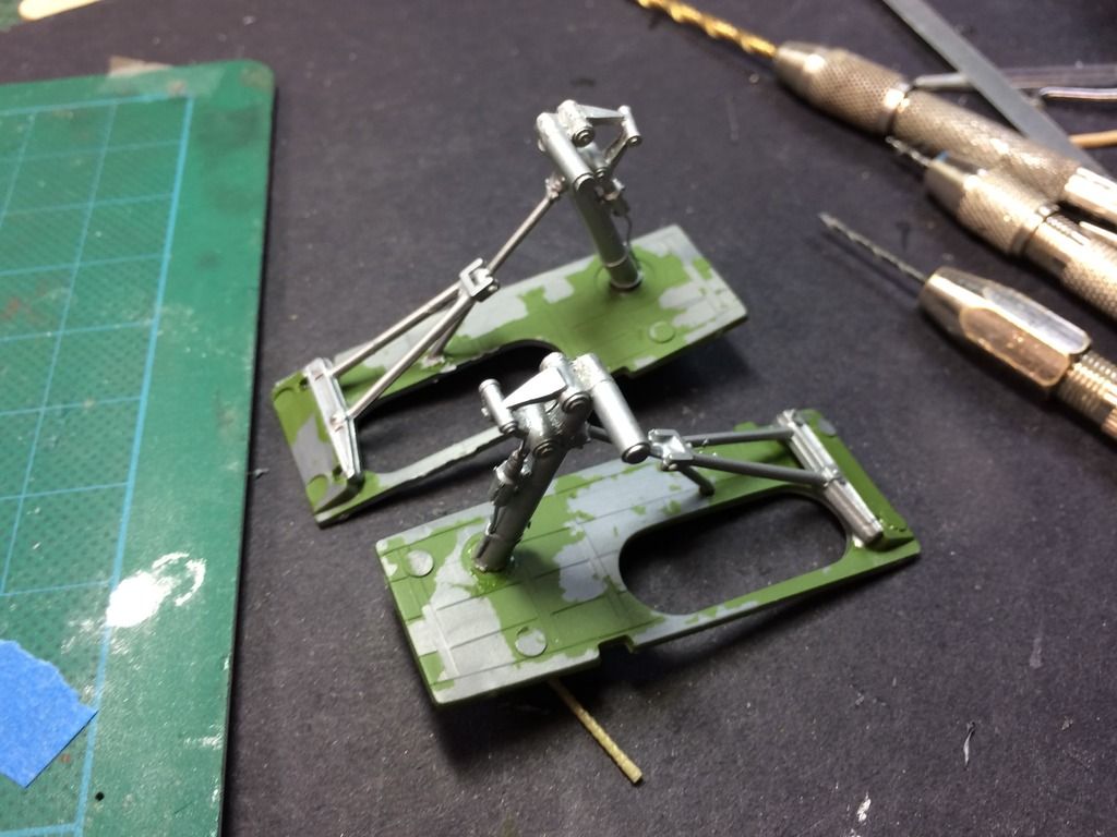
The landing gear is installed first into the upper Gear well sheet. This, in turn, is glued into the bottom wing. Before gluing anything, I tried the fit of this part into the wing, and quickly found out that both resin exhaust pipes leading to the turbos were too high and holding the gear sheets away from their mounting points. I took the Dremel and removed the excess resin until they fit properly.

I then CA'd the main gear struts into position. One of my brass locking arms had separated from one strut. I waited until the main gear was set and then got the locking lever into place and CA'd it fast. Next on was the gear actuating levers which were styrene kit parts. These parts needed a little coaxing since they were now mating with scratch-built metal parts. All in all, everything worked. 

When I was okay with the installation, I masked the bases to protect the interior green. This proved to be unecessary as you'll see in a moment. I sprayed it with the Tamiya Bare Metal rattle can spray, followed by Dullcoat.

After I pulled the tape I found that it pulled about half the green left the plastic. Most likely, it's because I don't wash my styrene before painting, and the Model Master Acrylic doesn't have the grip that Tamiya paints do. Makes a great peeling paint effect if I wanted that.

After brush painting to repair the missing paint, I painted the brake lines and the gear was done. I put on a light coat of alcohol/India ink mix to tone it all down. I also did this to the wheel hubs. With that the main gear are ready to install into the airframe.

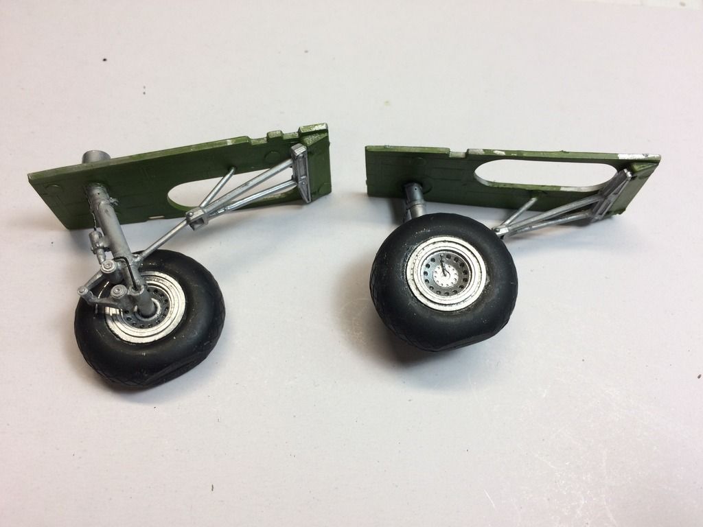
The tires have "weight flats". The kit's gear had an axle with two flats that aligned to the wheel hub's hole that was also shaped the same way. But the resin gear has a round axle. I had two choices, file flats on the gear axle or drill the wheel hole out to be round. I chose the latter since it was easier to control AND I can rotate the wheels to contact the ground properly before gluing them in place after the plane is finished. 

Machine Guns:

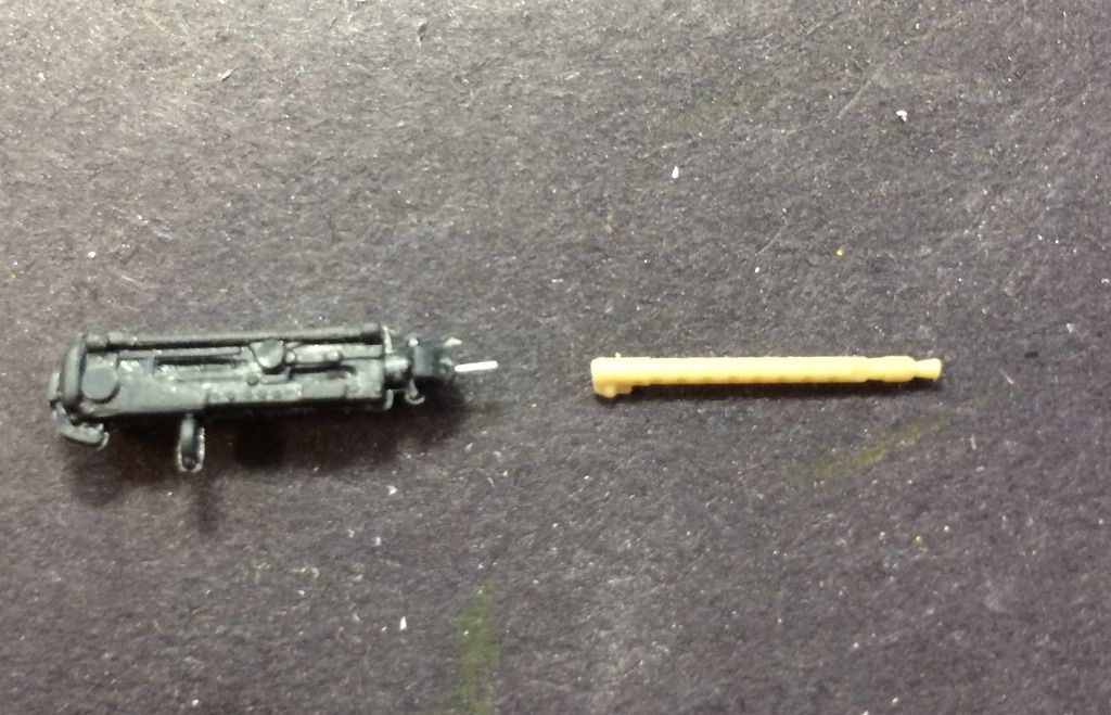
The Verlinden resin Brownings have separate very fine barrels and receivers. The problem is they're missing other aspects of the kit's guns that enable them to be mounted correctly in the model. So I'm making hybrids of all of them as I did with the top turret. With the waist and radio room guns, I used the same method, drilling the receiver and shaping the barrel so they were a tight fit and CA'd into place. For the bombardier compartment guns this method wouldn't work, since there's a lug on the barrel portion that goes into a fitting on the window. This part was too narrow to drill the barrel-sized hole, and a straight butt joint would be very fragile. I needed to pin the barrel in place.

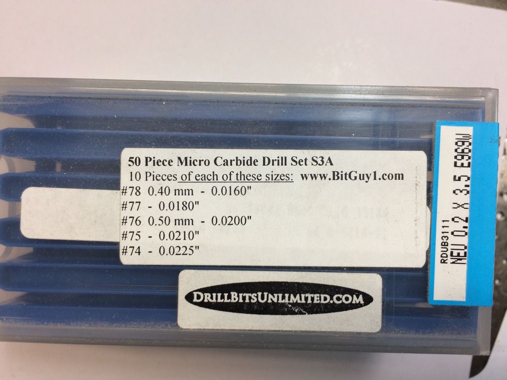
For very small diameter rods I use B and E guitar strings. The E string is 0.009". There's actually no drill size you can easily get that's this small. I have a selection of carbide drills that I buy from Drillbitsunlimited.com. This set has 10 each of small sizes and it's a good barging. But... there's a caveat. These are solid carbide and very brittle. A tiny bit of side thrust and "snap!". They are very sharp and originally are used to drill circuit board fiberglass. That sharpness is a blessing and curse. When drilling brass it's a curse since it grabs on exit and breaks the drill almost every time. I went through a ton of these when building the Missouri working with the PE.

Here's the drill I used. It's a #78 and is oversized for the guitar string, but with ample CA it ultimately held. They all have an 1/8" shaft so there's lots of support. These were originally used in automated drilling machines.

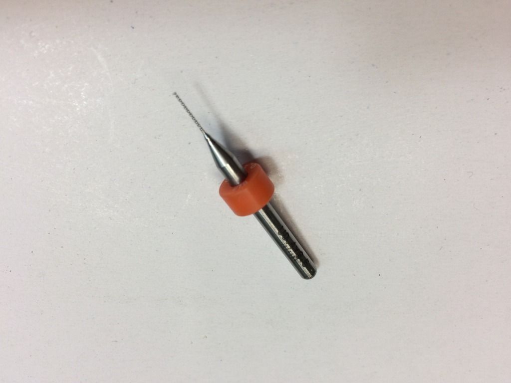
Here's the sequence. I file both the receiver and barrel mating surfaces flat and square. I then use a divider point to make a pin *** in as close to dead center as I can. I then use the #78 to drill both pieces.

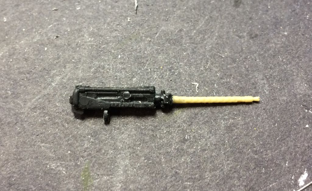
The newly joined barrel is reasonably strong. Here are all guns done today.

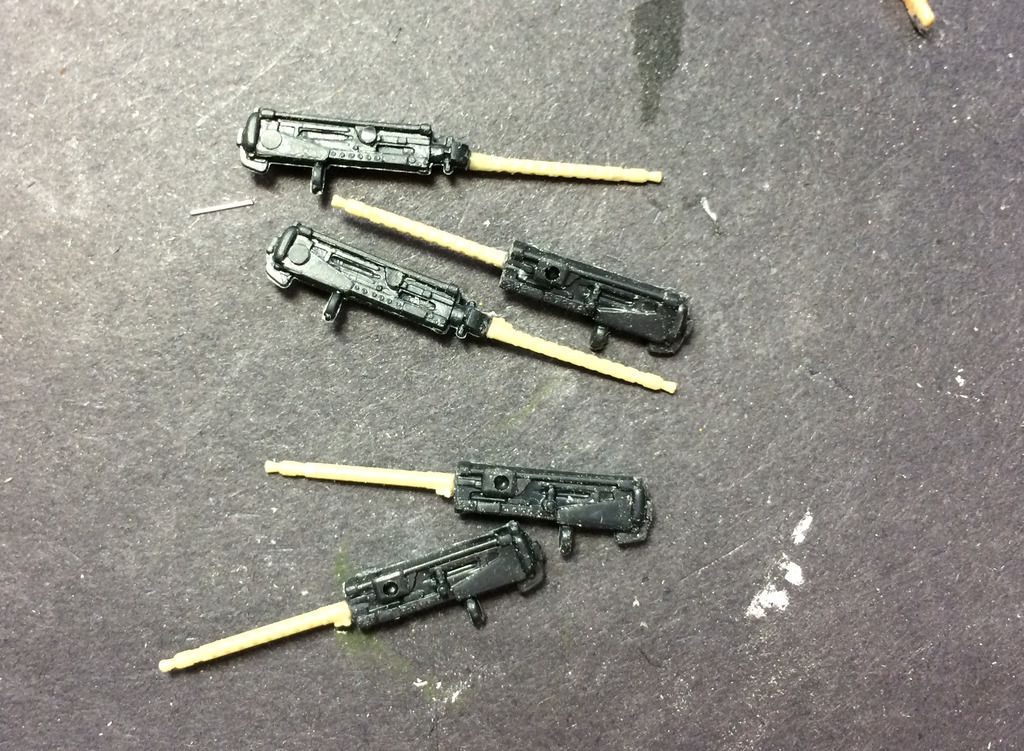
Before closing up for the day, I painted all the guns Tamiya Gunmetal. I had a problem with the chin turret. Its guns are noticeably longer than the rest and have flash shields on them. The Verlinden replacements are just too small. I may use the kits guns in this one instance. I like to paint the barrel tips silver. I don't know if this is prototypical, but I like the look.

Tomorrow, I'll finish the bombs and mount them to the bomb rack. This will pave to the way to start installing everything into the right fuze half including all the glazing and then put the Fuze together. The seams will need a lot of filling, and being an ancient kit, all the panel lines are raised. I'm not of spirit to shave them all off and engrave panel lines. I would wait until I build the HKM 1/32 scale bird which already has engraved lines. Meanwhile, the wings can also be built. From now going forward, the build is going to accelerate.

JOIN OUR COMMUNITY!

Our community is FREE to join. To participate you must either login or register for an account.

SEARCH FORUMS
FREE NEWSLETTER
By signing up you may also receive reader surveys and occasional special offers. We do not sell, rent or trade our email lists. View our Privacy Policy.