UPDATE 2 – 1/3/2015
Greetings All! The fun continues…
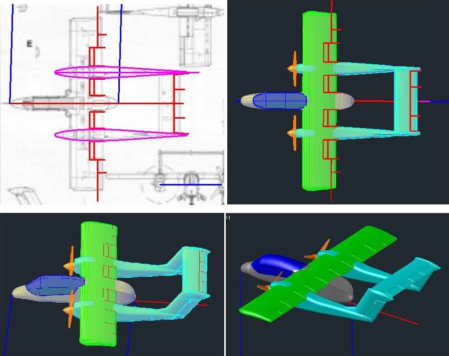
I started this session by detailing the wings and horizontal tail. Once again, the lines were traced from the plans, copied to the model, and projected onto the surfaces to create “etching tubes”, which were subtracted from the respective solids, as shown in the images below.
Due to the fairly low quality of the plans I am using, the slight bulge of the canopy wasn’t evident so mine was straight on the sides. To fix this, I created new sections with a bulge and lofted them to create new solids as shown in the top 2 images below. The pieces were joined, and then sliced to make the canopy and a fuselage segment. The corresponding section on the airframe was cut out, as shown in the lower image below.

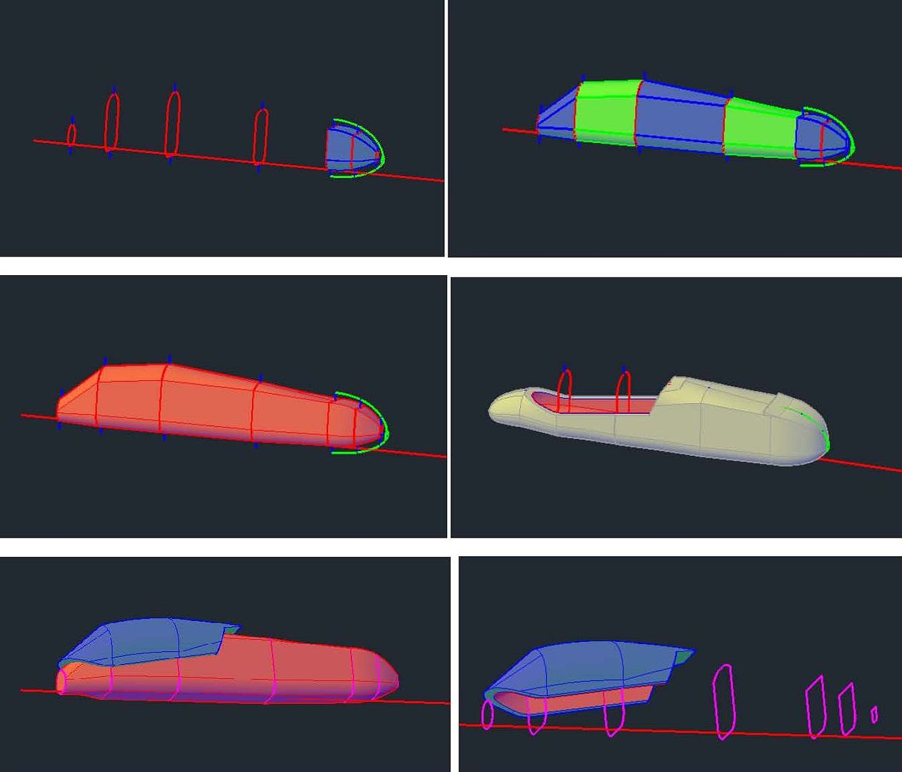
At this point I copied the 1/144 scale drawing file to another file and scaled it down to 1/350 scale. Everything being done from here out will be in 1/350 scale, unless stated otherwise. The first thing I did on the 1/350 scale model was to hollow out the fuselage. I typically make the shells ~0.02” thick because it’s as thin as I can make larger pieces and have them maintain enough strength for handling. AutoCad has a shell command but it often doesn’t work right, so I started by copying the sections I used to make the airframe, along with the reference line, up out of the way, then I drew 0.02” lines up from the bottom of the sections and down from the top of the sections, and scaled the sections to fit within the lines as shown in the upper left image below, which also shows the loft between the aft 3 sections. The sections were lofted (upper right) and joined together (middle left). The resulting solid was copied down to the airframe and subtracted from it to hollow it out (middle right). I also hollowed out the canopy as shown in the lower images.
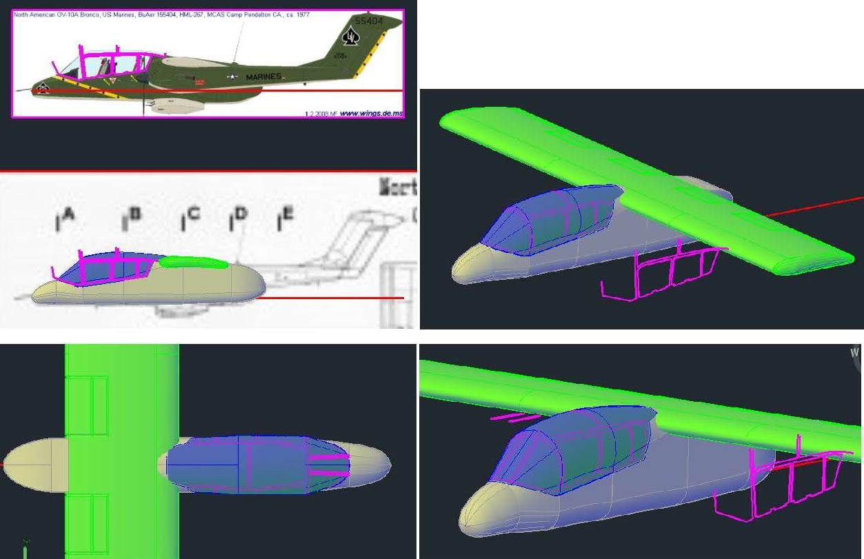
I turned my attention next to the canopy detailing. The upper left image shows the tracings from the Wings Palette plans copied to the model, and the upper right image shows these lines projected onto the canopy. To make the windscreen frame, I adlibbed them (lower left) and projected them down to the canopy (lower right).
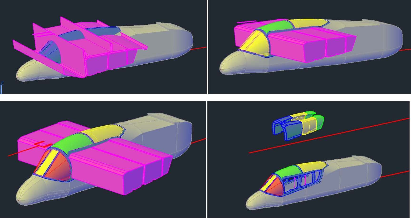
It should perhaps be noted that the projections are only used for reference, to make sure the lines are positioned correctly, and that they look right. To make the shapes I need I extrude the tracings through the canopy part. Doing this creates 6 shapes, 3 surfaces and 3 solids, as shown in the upper left image below. This is because, if you extrude a closed polyline, you get a solid. If you extrude an open line, you get a surface. The upper right image shows it after I have sliced the canopy along the 3 surfaces, and the lower left images shows it after I sliced the forward piece along the lines I drew for the windscreen. At this point, the 3 solids and canopy were copied up to the temporary reference line, and the intersect command was used (3 times) to create the “windows” and the 3 solids were subtracted from the canopy as shown in the lower right image.
The upper left image below shows the various “glass” pieces with the frame in blue. Each of the glass pieces was moved in ~0.004”. Some were moved horizontally, some vertically, and some a combination of both, as needed (upper right). Finally, the various pieces were all joined together again, as shown in the lower image.
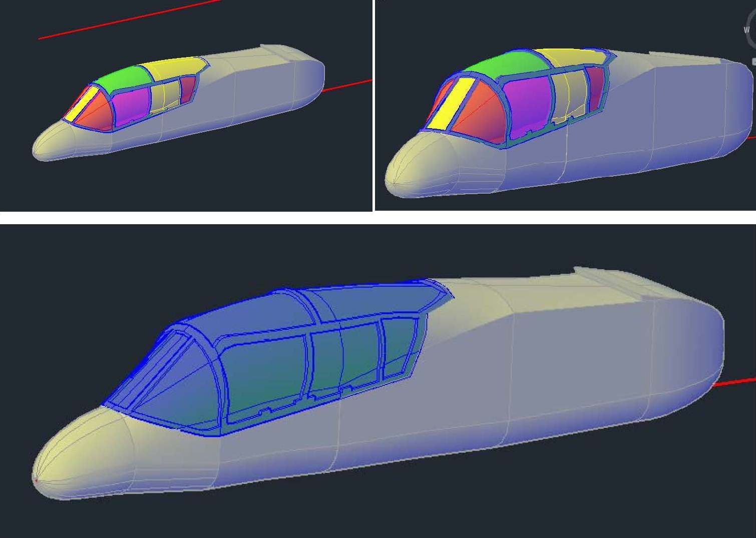
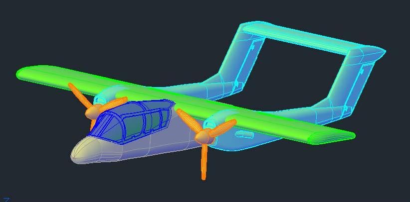
The image below shows the model at this point.
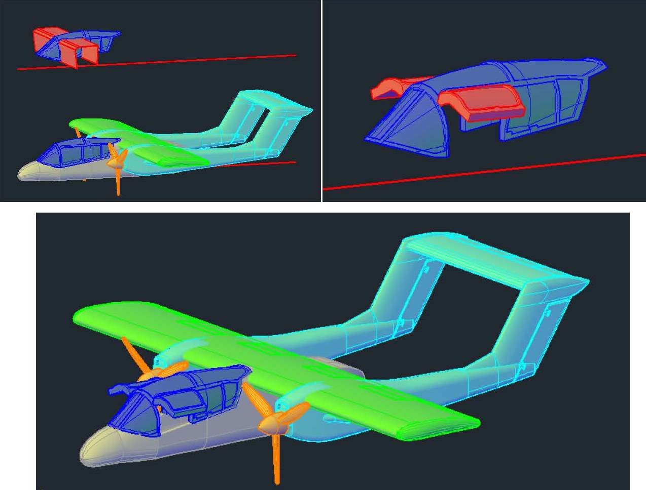
At this point I decided to make an open version of the canopy, so I copied it up to the reference line, sliced the windows out and rotated them up (upper images below). After making separate layers for the open and closed versions, I moved it down to the model, as shown in the lower image (Note that the closed canopy layer is turned off).
At this point I turned my attention to the gear. I started by slicing the plug to make 0.01” thick doors, as shown in the upper left image below. To provide the modeler the option of displaying the model in-flight with the gear doors closed, I copied the doors up to the temp reference line, etched them and mirrored them (upper right). I again made separate layers for the gear doors and the gear. Next, I rotated the doors to the open position, (lower left), then created solids extending from the doors up into the plug (lower right).
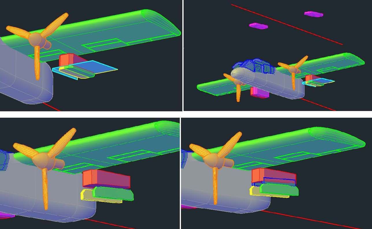
Before continuing further on the doors, I decided I needed wheels, so I opened my “Wheels” drawing and copied the blue wheel in the upper image below into the OV-10 drawing. The wheel was then scaled to match the plans.
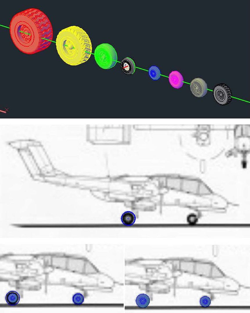
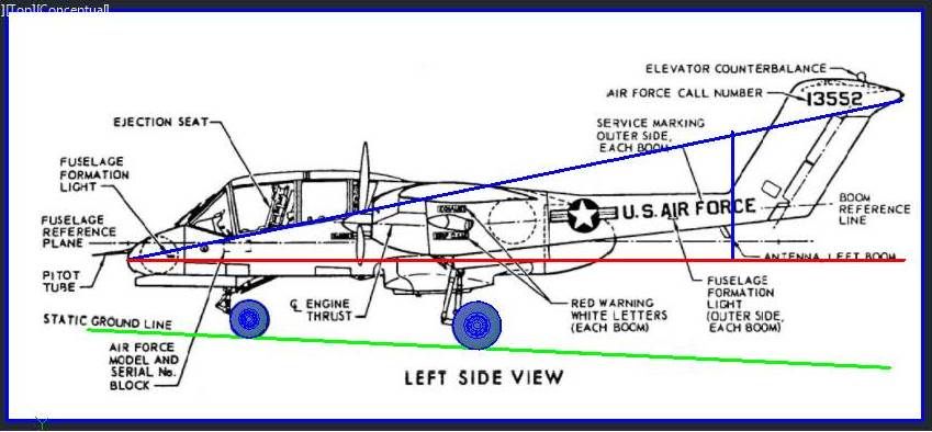
At this point I import a better left side view image I had found and scaled it to size. I copied the wheels to their appropriate locations, and then realized that the doors I had previously cut out, etc. were wrong. I guess I’ll start with that in my next session.
CHEERS!!!