SEARCH FINESCALE.COM

Enter keywords or a search phrase below:

North American OV-10 Bronco (1/350 and/or 1/144 Scale)

13643 views
22 replies
1 rating 2 rating 3 rating 4 rating 5 rating
  • Member since
    March 2012
Posted by Rdutnell on Monday, December 21, 2015 9:52 PM

Oops! I screwed up inserting the pix.  Let me try again.

Hoefully I did it right this time.

  • Member since
    March 2012
Posted by Rdutnell on Monday, December 21, 2015 9:31 PM
UPDATE 14 – 12/21/2015
Hi Everybody!
Well, although I completed my dissertation, I haven’t had much time for modeling because I had the opportunity to teach an AutoCAD class at OU this past semester.  It was fun, but it sure took a lot of time.  Anyway, I finally got some free time and the first thing I did was make the base.
 
After cleaning the model, I then painted it using Model Master acrylic paints (for the most part).
 
After everything was painted I assembled the model, except for the propellers, which I decided to wait and put on after I put the decals on.  The model pops a wheelie due to the large tail moving the center of gravity aft, so in the photo below it is held level with a discarded 3D print of a building.
 
Next I put on the decals that I also made using AutoCAD and had printed by Yuuichi Kurakami.  The decals came out nice and went on fairly easily.  I did have two slight issues.  First, the Bu numbers were supposed to be black but were printed in white.  Because the white stood out so much I decided not to include them.  The other issue was that I failed to include the black bits on top of the wings, so I got back on AutoCAD and traced the outline as seen in pictures, printed it to scale, cut it out and then used it as a template to cut out a piece from a black decal I had laying around.   It was much easier than painting it would have been and it looks better too.  I then put on the propellers, but broke a blade off of each of them in the process.  I did a decent job fixing the starboard side, but not so good on the port side.
 
With the model completed, I had a brass plaque made at Sooner Trophies that I had them screw to the top-front of the base.  Here are some pix of the completed display.
 
 
  • Member since
    March 2012
Posted by Rdutnell on Thursday, May 21, 2015 2:44 PM

Cyanoacrylate (AKA superglue).

  • Member since
    August 2013
Posted by Jay Jay on Thursday, May 21, 2015 2:29 PM

I tried Testor's clear cement but it wouldn't hold very well on the fsg.


 I'm finally retired. Now time I got, money I don't.

  • Member since
    August 2013
Posted by Jay Jay on Thursday, May 21, 2015 2:28 PM

What glue do you use on these?  I had a heck of a time with mine trying to keep the canopy clear with out fogging them.


 I'm finally retired. Now time I got, money I don't.

  • Member since
    March 2012
Posted by Rdutnell on Thursday, May 21, 2015 2:16 PM

Hi Guys!

It has been over 5 months since I last posted that I had ordered the OV-10s and would post pictures of them when I received them.  Well, although I received the models some time ago, I have been too busy completing my dissertation and defending it to even open the box.  With that behind me, I finally found time to open it and take pix.


I’m happy with the results.  The next step is cleaning the parts.  Hopefully, I will now have some time to work on it.

CHEERS!!!

  • Member since
    March 2012
Posted by Rdutnell on Friday, January 16, 2015 7:56 AM

Hi Guys!

I uploaded the Ov-10A to C2d and they have activated it.

https://www.click2detail.com/store/p345/North_American_OV-10A_Bronco__1%2F350_scale.html

I’ve already ordered 2 of them.  I’ll take pictures of them when I get them.

  • Member since
    March 2012
Posted by Rdutnell on Wednesday, January 14, 2015 5:25 PM

UPDATE 11

Hi Again Guys!

Before starting on the part fret, I decided to add “spinning” props, which will be printed in clear plastic.

After I finished the props, I put the smaller parts on a fret.  The image below shows all of the parts in the models kit.

I next made a parts diagram for the model…

…Then “exploded” the model to better show the parts.

The last thing I did was make the decals.  The images below show the left and right side of the model with the decals “on” it, and the decal sheet I made.  The sheet is 0.75”w x 0.4”h.

I will post the model on Click2Detail (C2D) later tonight or tomorrow, and place my order.

  • Member since
    March 2012
Posted by Rdutnell on Wednesday, January 14, 2015 9:01 AM

UPDATE 10

Good Morning All!

I decided to go ahead and include the missile pods and to make the pylons part of the airframe.  The upper left image below shows the pylons joined to the sponsons.  You can also see the attachment pins in red.  The upper right image shows the corresponding attachment holes in the rocket pods.  Note that I also decided to make the pods without the fairings.  The lower image shows the two different rocket pods and the gun pod on the model.

The image below shows the completed(?) model, unless anyone sees something I’m missing or should include.

The next step is putting the small parts on frets.

  • Member since
    March 2012
Posted by Rdutnell on Monday, January 12, 2015 9:28 AM

UPDATE 9

Another fine morning if you are fond of near freezing, overcast, and windy weather.

I was able to add some more of the detailing features to the OV-10 over the weekend.  Continuing where I left off in my last post on Saturday, I copied the pylon I had made previously to the gun pod, as shown in the upper left image below.  The remaining three images show the making of the aft boom antennas.  First I traced the drawing lines from the plans (upper right) to create a solid (lower left), then moved the solid to one boom and copied it to the other (lower right).  

Next I made the forward boom antennas as shown in the upper images below.  At this point I learned that my brother-in-law was with VMO-1 out of New River in 1979 or 80.  He said that there were 16 planes in the squadron and they flew in which ever one was assigned for the mission. I got on the internet and was able to find several pix of VMO-1 OV-10’s and noticed that they had a hump on top of the airframe near the aft end.  I decided to add it, which I did using a series of ellipses lofted together, as shown in the lower images.


Next, I etched the outline for the rear cargo door as shown in the upper images below, added the wingtip lights (lower left) then the nose light and pitot tube (lower right).

The pitot tube is only 0.01” diameter, and although it would print if I joined it to the airframe, it would certainly get knocked off during the cleaning, shipping, building process, so I am leaving it separate.  The upper left image below shows the 0.011” hole I drilled in the airframe to accommodate the pitot.  Although I am leaving it on the drawing, the pitot could probably be made out of wire during the building phase, so I don’t think I will print it.  I next added the forward fuselage formation lights (upper right) followed by the aft ones (lower left).  I also made the sponson pylons (lower right).

The “Combat Bronco ‘Night’ Ordnance Configurations” drawing I have shows that the OV-10 carried LAU-59 rocket pods. I couldn’t find a good drawing of the LAU-59, but I found dimensions (62.4”L x 9.8”D) and a good drawing of the LAU-3.  When I scaled the length to 1/350 scale (0.18”) the diameter was spot on (0.03”), so I used the plans to make one and then copied it to the pylons, as shown below.  Note that the gun pod later is turned off and the fuel tank layer is on.

The last image of the day shows the front view with all four pylons carrying rocket pods. I haven’t attached them because I’m not sure how I am going to do them, or if I even want to include them.  Any thoughts?

  • Member since
    March 2012
Posted by Rdutnell on Saturday, January 10, 2015 10:53 AM

UPDATE 8

Hi Everybody!

In the process of looking for pix, plans and dimensions for the SUU-11/A gun pods, I stumbled across yet another helpful image on-line that shows side view drawings of the OV-10A with Navy Light Attack Squadron 4 (VAL-4) “Black Ponies” and the YOV-10D with Marine Observation Squadron Two (VMO-2) as shown in the upper left image below, after I import it into AutoCad and scaled it.  Two things jumped out at me in this drawings.  First of course is the gun pod. Second, it looks like it would be easy for me to convert my OV-10 to a YOV-10D, but that is for another day.  The upper right image below shows a close up of the gun pod on the drawing.  I started by drawing a line down the center axis of the gunpod, and drawings circles where the diameter changed.  I also traced the forward end with an open polyline and aft end with a closed polyline.  I then rotated the circles 90o and lofted between them , then (after slicing the it in half) I rotated the aft polyline around the central axis, as shown in the lower left image.  The lower image shows it after I added the gun barrel.

Next I added some detailing to the gun pod.  The upper left image below shows the “etching tubes” I made.  The upper right image shows it after I subtracted them, and the lower image shows it copied to the airframe.

To be continued…

  • Member since
    March 2012
Posted by Rdutnell on Friday, January 9, 2015 10:53 AM

UPDATE 7 – 1/9/2015

Good Morning All!

With the model mostly completed the last thing I do is add features of the aircraft that stand out in pictures.  This is where my lack of knowledge about the aircraft is a drawback.  I know that there were numerous versions, with the majority being OV-10A’s, but I don’t know what the differences are.  I will see a feature in one picture, but it won’t be in the next picture.  An example is the objects on top of the vertical stabilizers, as shown in the upper left image below.  I at first thought they were lights, but I’m not sure that that is what they are, because closer examination of pictures (after the following session was completed) shows a light in the center of the tail plane, which seems more typical.  Whatever they are, I added them and the counter weights, as seen in the images below.

One feature very common in pictures is the centerline fuel tank.  I had found a figure showing the “Combat Bronco ‘Night’ Ordnance Configurations” which shows an “Aero 1C Fuel Tank”.  I searched on line and the closest plans I found was for the Aero 1D Fuel Tank, so I used it.  After copying it and scaling it to size I traced the outline and used the revolve command to create the tank, as seen in the top two images below.  Note that the plans show 0, 2 and 4 fin configurations.  Since the fuel tanks in all of the pictures I have seen don’t have fins, I didn’t include them.  Next I copied the tank to under the airframe, but it looked a little long to me, so I scaled it 90% to better match the size seen in pictures.  (I later found dimensions for the Aero 1C and at 1/350 scale it would be 0.51” long and mine is 0.58” long.)


With the tank made the next thing I did was make the pylon for it.  The upper left image below shows the shape I extruded through the airframe after I had copied it and the airframe up to the reference plane and used the subtract command followed by the separate command to create 3 new solids, 2 red and one green.  The red ones were deleted, the green one was copied down to the airframe (after deleting the existing one), as shown in the upper right image.  The lower left image shows the resulting pylon with attachment points being made using 0.015” diameter posts.  The lower right image shows the final tank/pylon assembly moved down from the airframe showing the recesses I cut out (using 0.016” diameter posts).

That’s all for now…

  • Member since
    March 2012
Posted by Rdutnell on Thursday, January 8, 2015 11:43 AM

UPDATE 6 – 1/8/2015

Good Morning All!

Now for the cockpit.  Even though my models are all 1/144 or 1/350 scale, the more recent ones include interiors.  Although it likely will not be seen for the most part, it is fun and somewhat challenging to do.  I typically do not have plans of any sort and have to rely on pictures I find on-line.

To do the OV-10 interior I started by tracing the outline of the top parts of the instrument panels and seats from the Wings Palette.  I then extended them down below what can be seen on the plans and extruded them through the airframe. Next, I lofted between the forward two sections used to hollow out the airframe (upper left image below), and used the intersect command on it and the IP extrusion (upper right).  I then lofted between the aft three “hollowing” sections (lower left) and used the intersect on it and the pilot’s seat, then repeated the process for the observer’s IP and  seat (lower right).

The upper left image below shows it at this point from a different angle with horizontal lines (blue) drawn in preparation for slicing the seats.  (Note that I also modified the observers IP slightly) The upper right image shows it after I have sliced the seats, but before I have deleted the parts I don’t need.  The lower left image shows it after I deleted the unwanted parts, and in the lower right image I have sliced the back seat in the front (or back) view plane.  You can see the lines I used on the right side of the image in red.

The top two images below show it with both seats trimmed, the right one showing it with the airframe layer turned on.  The lower images show the result of lofting the hollowing sections (left) and using the intersect command on it and the modified observer’s IP (right).  You can also see the deck I created using the same method (magenta).

The next thing I did was make the side panels, I did this again using the same methods as before.  After doing this, I sliced them into sections as seen in the upper left image below.  Next, I prepared the solids to cut out the recesses for the pilot’s feet (upper right), which I cut out, before doing the same for the backseat (lower images), which I would later realize, don’t exist and have to redo.

The next set of images show the final steps in making the pilot’s IP (top) and the observer’s IP (bottom).  Both involved more dicing and slicing.

The upper left image below shows it after I have joined all of the various pieces using the union command.  The upper right image shows it after I have joined the assembly to the airframe, and the lower image shows it with all layers turned on except for the canopies.

I haven’t done any detailing on the interior aft of the cockpit because I have yet to find good pictures of it.  If I find some I will do it as well.  The model is almost completed at this stage with the final step being looking at pictures for other details I should add, such as lights, antennas and handles, but that is for another session.

CHEERS!!!

  • Member since
    March 2012
Posted by Rdutnell on Wednesday, January 7, 2015 8:48 AM

Ahhh! When you say it like that it makes perfect sense.

  • Member since
    March 2009
  • From: Yorkville, IL
Posted by wolfhammer1 on Tuesday, January 6, 2015 10:37 PM

Don't feel bad.  It really is not intuitive that the tail "lifts" down to hold the nose up.  Only a plane with the tail on the front, called a canard, has all of the wings lifting.

John

  • Member since
    March 2012
Posted by Rdutnell on Tuesday, January 6, 2015 5:56 PM

UPDATE 5 – 1/6/2015

Greetings All!

I fattened up the sponsons, although I didn’t document the process.  After that, I did the front landing gear.  I typically use bottom view plans to trace the outlines of the doors, but in this case the plans are so poor that this wasn’t possible, so I traced the doors from the side view plans as seen in the upper left image below.  I then mirrored the tracing around the centerline and rotated it 90o (upper right).  Note that I also added a small rectangle aft of the tracings.  I then extruded the 3 polylines into the airframe to create 3 solids (lower left).   At this point I copied the solids and airframe up to the reference line and used the intersect and subtract commands to make the doors and cut out the recess for the gear (lower right).

Next, I sliced the solids for the doors to create 0.01” doors (upper left image below).  I then created copies for the closed doors, that I etched details into (upper right).  The lower left image shows the closed doors on the model in “Realistic Visual Style”.   The next thing I did was turn off the closed door layer, turned on the gear layer and rotated the doors to match the plans and pictures the best I could (lower right).

At this point, I used the nose gear plans to make the gear itself, as shown in the images below.  The upper left image shows the gear midway through construction, and the upper right image shows it completed, except for the aft linkage, but the lines for the linkage bracket may be seen on the right.  Everything was made by extruding and lofting circles and rectangles at least 0.01” across.  The lower image shows the gear after joining the various parts and copying it to the airframe.

Next I completed the aft linkage as shown in the upper left image below.  The upper right image shows it with the airframe layer turned off after I joined the gear pieces together and extruded rectangles up from the top of the gear doors to match the cutout in the airframe.  The image at lower left shows two cross supports I added for strength.  After joining the supports to the rest of the gear assembly, I copied it and the airframe up to the reference line (lower left).

I then subtracted the copied airframe from the gear assembly.  The result is shown in the upper left image below.  Because I was afraid the aft bit would be too fragile I added a support arm connecting the end to the body as shown in the upper right image.  The image below shows the completed nose gear.

The image below shows the model as it currently stands.

CHEERS!!!

  • Member since
    March 2012
Posted by Rdutnell on Monday, January 5, 2015 11:03 AM

UPDATE 4 – 1/5/2015

Good Morning All!

Continuing on the model, I started on the sponsons last night.  For my first try at it, I decided to try to use a scaled vertical stabilizer section to make it.  The upper image below shows the copied and scaled section in position on the plans.  The lower image shows the front view plans with the center lines of the sponsons drawn.

The upper image below shows the model in “3D Wireframe Visual Style” with the plans layer turned on, making it somewhat “busy” so it is somewhat difficult to decipher, but you can see that I have copied and rotated the sponson alignment lines to the model, and copied the section to the intersection of the lines in the center of the airframe (both in magenta).  I have also used the copied and scaled section to create the sponson tip (yellow).  To do this I sliced the section, to create a half-section, and revolved the half-section around the center line to make a solid.  In the lower image, shown in “Conceptual Visual Style”, I have rotated the section perpendicular to the alignment lines and extruded it down and out to the sponson tip.

Although I am fairly happy with it, I’m not totally satisfied because I think that it needs to be fatter.  I’ll give it another go next session.

CHEERS!!!

  • Member since
    March 2012
Posted by Rdutnell on Sunday, January 4, 2015 8:03 PM

UPDATE 3

Hi Guys!

I started today’s modeling session by fixing the tail plane inaccuracy pointed out by John.  I started by copying the model and needed guide lines to the left (upper image below).  I was able to do this because I save every line I use on a “Misc” layer.  The lines may be seen on the copied model because I changed them to the base layer.  Next, I sliced the top part off and copied it up as shown in the lower left image.  After this, I extruded the shape I used to make the tail plane through the copied shape, then used the intersect command to isolate the plane, which I then mirrored to flip it over, as shown in the lower right image.

Next I deleted the tops of the booms off and recreated them with the guidelines, as shown in the upper left image below.  I then moved the flipped sail plane down into position as shown in the upper right image.  The lower image shows it after I rejoined everything back together.

Yesterday I mentioned that the gear doors I had made were too far back.  You can see what I was talking about in the image below.

I started the repair by first rejoing the plugs to the airframe.  I then redrew the polylines defining the doors and extruded them into the boom as shown in the upper left image.  As before I copied the boom and newly extruded shapes up and used the intersect command to create the new plugs, and the subtract command to create the recesses in the booms (upper right).   I then sliced the plugs to make 0.01” thick doors, and copied the doors up to make the closed doors as shown in the lower left image.  Next I rotated the doors down to the open position (lower right).

Usually I have to do quite a bit of adlibbing on the wheels, but in this case I found some good plans on-line, so I copied them into the drawing and scaled them to match the wheel as shown in the left image below.  The images on the right show some of the initial tracings and solids I used to make the gear.

More of the pieces I made are shown below. 

The image below shows the completed gear. (I mirrored the one I made to the right side).

The image below shows the gear parts lowered away from the booms.

CHEERS!!!

  • Member since
    March 2012
Posted by Rdutnell on Sunday, January 4, 2015 7:45 AM

IKES!

Thanks John!  I appreciate the kind words and the comment.  I never realized that the tail plane was inverted like that.  One of the reasons I like to post my WIPs is because of input like this.  Since I know little about airplanes, I really need and like, the feedback I get, even if it does mean more work.  Smile

Still, being the skeptic that I am, I looked up “horizontal tail section” on-line and sure enough it really is an upside down foil.  You learn something new every day.

Fixing it isn’t going to be easy, and I’ll have to figure out the best way to do it, without simply redoing it all.

Thanks again!

  • Member since
    March 2009
  • From: Yorkville, IL
Posted by wolfhammer1 on Saturday, January 3, 2015 9:12 PM

Nice bit of design work.  One comment, you might want to invert the tail plane relative to the main wing, as that is probably how it is shaped.  Otherwise, wow.

John

  • Member since
    March 2012
Posted by Rdutnell on Saturday, January 3, 2015 8:18 PM

UPDATE 2 – 1/3/2015

Greetings All!  The fun continues…

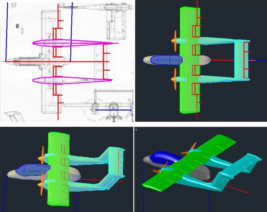
I started this session by detailing the wings and horizontal tail.  Once again, the lines were traced from the plans, copied to the model, and projected onto the surfaces to create “etching tubes”, which were subtracted from the respective solids, as shown in the images below.

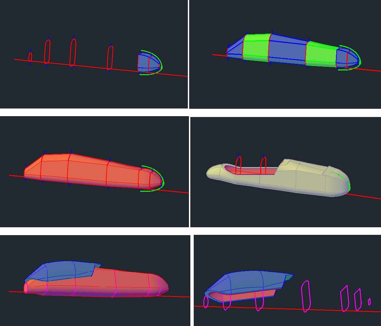
Due to the fairly low quality of the plans I am using, the slight bulge of the canopy wasn’t evident so mine was straight on the sides.  To fix this, I created new sections with a bulge and lofted them to create new solids as shown in the top 2 images below.  The pieces were joined, and then sliced to make the canopy and a fuselage segment.  The corresponding section on the airframe was cut out, as shown in the lower image below.

At this point I copied the 1/144 scale drawing file to another file and scaled it down to 1/350 scale.  Everything being done from here out will be in 1/350 scale, unless stated otherwise.  The first thing I did on the 1/350 scale model was to hollow out the fuselage.  I typically make the shells ~0.02” thick because it’s as thin as I can make larger pieces and have them maintain enough strength for handling.  AutoCad has a shell command but it often doesn’t work right, so I started by copying the sections I used to make the airframe, along with the reference line, up out of the way, then I drew 0.02” lines up from the bottom of the sections and down from the top of the sections, and scaled the sections to fit within the lines as shown in the upper left image below, which also shows the loft between the aft 3 sections.  The sections were lofted (upper right) and joined together (middle left).  The resulting solid was copied down to the airframe and subtracted from it to hollow it out (middle right).  I also hollowed out the canopy as shown in the lower images.

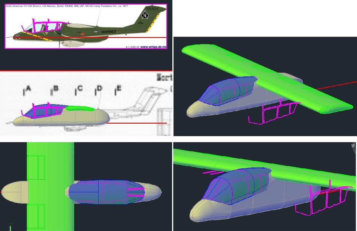
I turned my attention next to the canopy detailing.  The upper left image shows the tracings from the Wings Palette plans copied to the model, and the upper right image shows these lines projected onto the canopy.  To make the windscreen frame, I adlibbed them (lower left) and projected them down to the canopy (lower right). 

It should perhaps be noted that the projections are only used for reference, to make sure the lines are positioned correctly, and that they look right.  To make the shapes I need I extrude the tracings through the canopy part.  Doing this creates 6  shapes, 3 surfaces and 3 solids, as shown in the upper left image below.  This is because, if you extrude a closed polyline, you get a solid.  If you extrude an open line, you get a surface.  The upper right image shows it after I have sliced the canopy along the 3 surfaces, and the lower left images shows it after I sliced the forward piece along the lines I drew for the windscreen.  At this point, the 3 solids and canopy were copied up to the temporary reference line, and the intersect command was used (3 times) to create the “windows” and the 3 solids were subtracted from the canopy as shown in the lower right image.

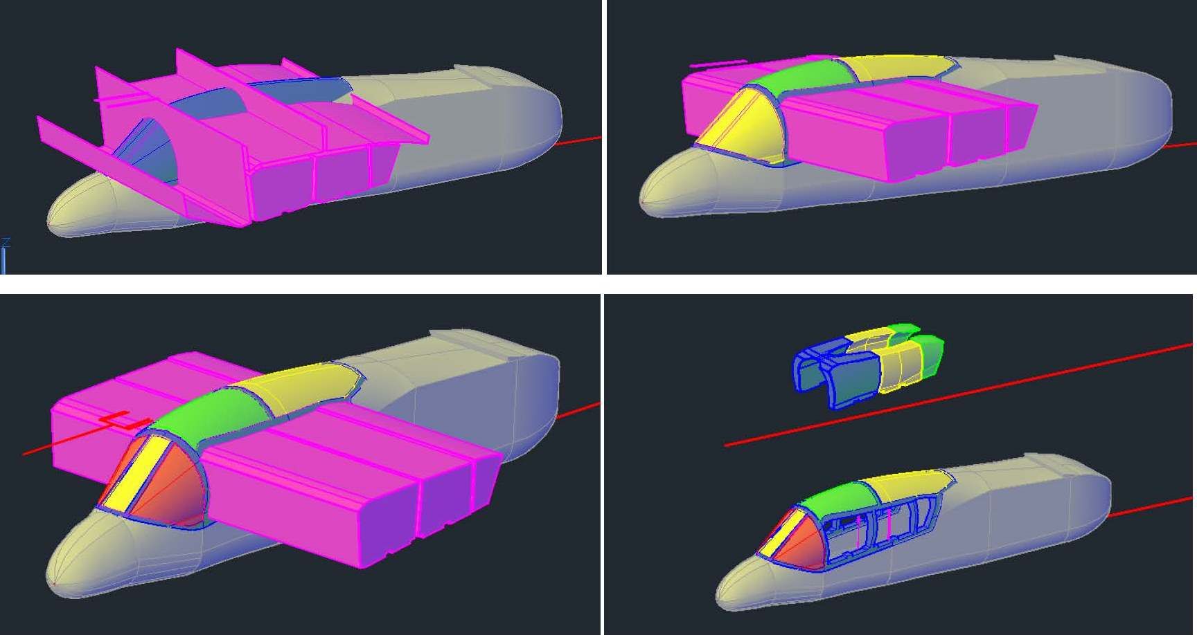
The upper left image below shows the various “glass” pieces with the frame in blue.  Each of the glass pieces was moved in ~0.004”.  Some were moved horizontally, some vertically, and some a combination of both, as needed (upper right).  Finally, the various pieces were all joined together again, as shown in the lower image.

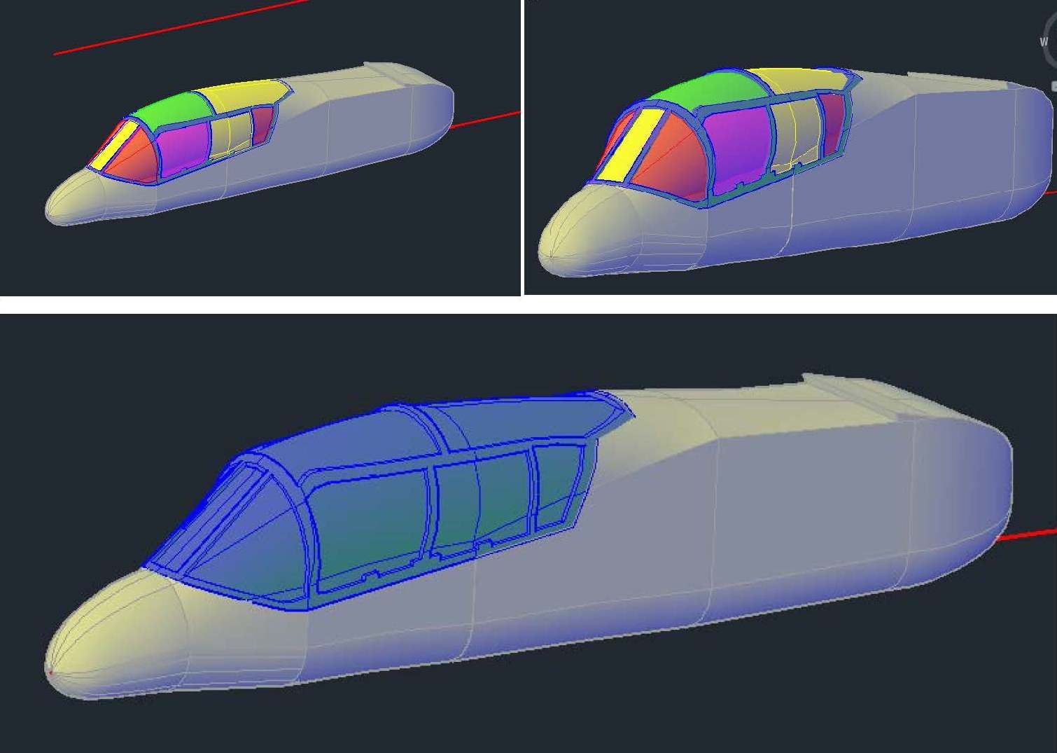
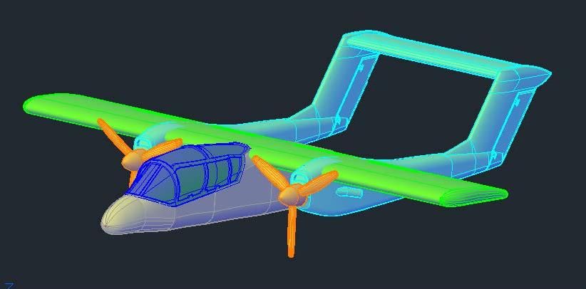
The image below shows the model at this point.

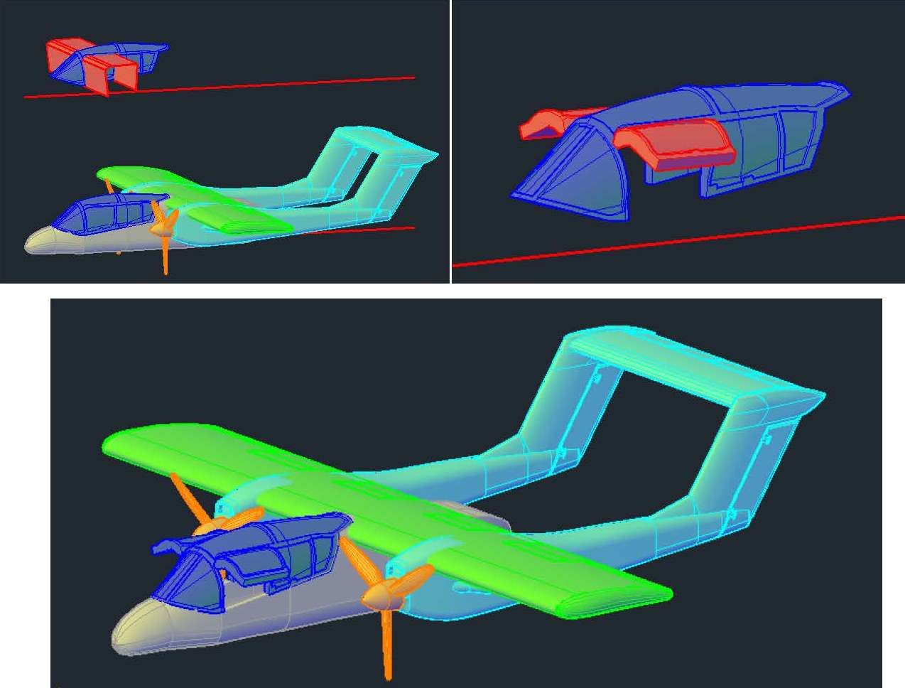
At this point I decided to make an open version of the canopy, so I copied it up to the reference line, sliced the windows out and rotated them up (upper images below).  After making separate layers for the open and closed versions, I moved it down to the model, as shown in the lower image (Note that the closed canopy layer is turned off).

At this point I turned my attention to the gear.  I started by slicing the plug to make 0.01” thick doors, as shown in the upper left image below.  To provide the modeler the option of displaying the model in-flight with the gear doors closed, I copied the doors up to the temp reference line, etched them and mirrored them (upper right).  I again made separate layers for the gear doors and the gear.  Next, I rotated the doors to the open position, (lower left), then created solids extending from the doors up into the plug (lower right).  

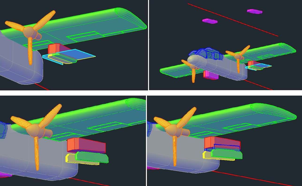
Before continuing further on the doors, I decided I needed wheels, so I opened my “Wheels” drawing and copied the blue wheel in the upper image below into the OV-10 drawing.  The wheel was then scaled to match the plans.

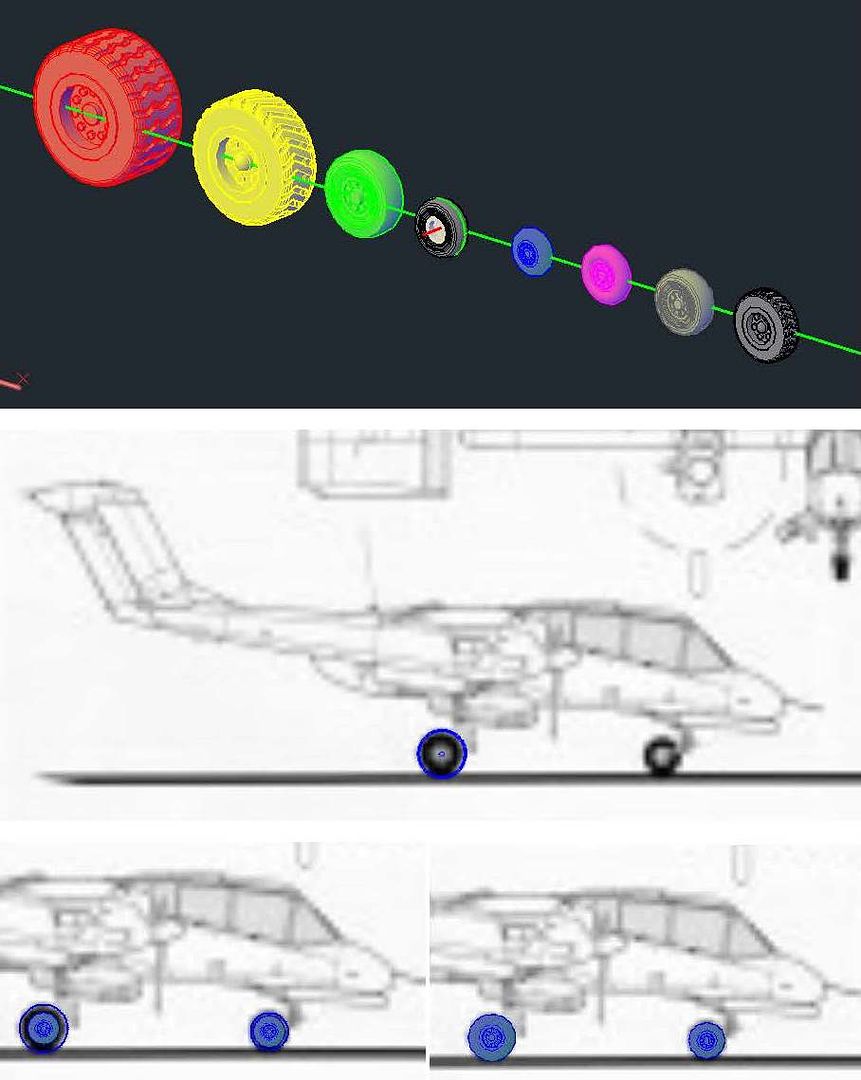
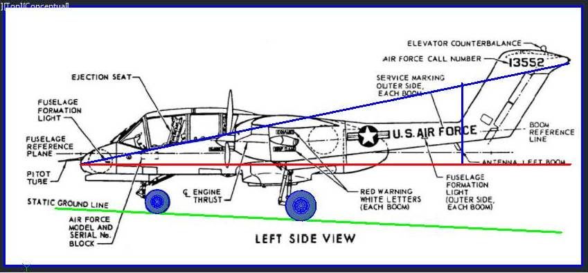
At this point I import a better left side view image I had found and scaled it to size.  I copied the wheels to their appropriate locations, and then realized that the doors I had previously cut out, etc. were wrong.  I guess I’ll start with that in my next session.

CHEERS!!!

  • Member since
    March 2012
Posted by Rdutnell on Friday, January 2, 2015 7:42 PM

UPDATE 1

Hi Everybody!

Well, my license must have expired, but I reinstalled the latest AutoCad and everything is working now.  I redid the work I lost on the boom and added the vertical tail, as shown below..

Next I added the transition section between the boom and tail (top images, below) and added the part of the foremost segment of the boom (lower image).

After this, I made the top part of the foremost segment of the boom (upper left image, below), extruded a closed polyline I made for the intake (upper right), then using the subtract command cut out the intake (lower left).  At this point I copied a propeller I had made for the 1/144 scale Cessna 421 (http://cs.finescale.com/fsm/modeling_subjects/f/48/t/162600.aspx), and scaled it up just slightly (lower right).

After moving the propeller into position, and cutting a recess for it out of the boom, I decided to redo the aft end of the boom extending it further aft.

Next I added the exhaust pipe on the side of the boom.  The image below show the tracings made on the Wings Pallette plans and copied to the model.  There is a circle, a line and an ellipse.  Note that I had to change the elevation of the lines so that they appear above the model.

To aid in construction of the exhaust pipe, I used another handy AutoCad command, Project Geometry and projected the tracings onto the boom.  I then copied the line I had projected onto the end point of the projected line, rotated the line out away from the boom about 30 degrees, and drew a circle perpendicular to the line, on the end of the line (upper left image, below), and extruded the circle along the rotated line (upper right).  The pipe was too far back, so I moved it forward slightly and added the collar by lofting between the ellipse and another circle part way up the tube (red in lower left image).  The lower right image shows it after I used the union command to join the parts to the boom.

Next, I started the surface detailing by tracing the outline of the rudder from the Wings Pallette plans (upper left image below), copying the tracing to the model (upper right), and projecting the tracing unto the tail (middle left).  To “etch” surface details I create solid tubes along the projected lines, using extruded and lofted circles, which I then subtract from the solid, leaving a channel cut in the surface of the solid.  I typically make these using 0.004”-0.006” radius circles, with the absolute minimum being 0.003”.  In this case, the model is currently at 1/144 scale, but I want to be able to print it at 1/350 scale, so I used a 0.0075” radius circle.  The middle left image below shows the beginnings of the tube.  The lower left shows the completed tubes. Note the bottom and aft parts are red and not joined to the rest of the tube in green.  This is because I could use symmetry to save time and mirror imaged the green bit to the other side before joining all the parts together.  The lower right image shows it after I subtracted the tube.

The last remaining detail that needed to be added to the boom was the main gear housing and doors.  I started, as usual by tracing them on the plans (upper left image, below) and moving and rotating one to below the boom (upper left).  After chamfering the corners (middle left), I extruded it into the boom and copied it, the boom and a reference line down a bit (middle right).  I then used the subtract command to create a cavity in the boom, and the intersect command to create a plug (lower left), that I moved up into the boom (lower right).  Part of this plug will be used to make the gear doors and some of it will be rejoined to the boom, but this will be done differently for 1/350 scale than 1/144 scale, so this is as far as I wanted to go at this point.

At this point I mirrored the boom, plug, and prop to the other side of the fuselage (upper images below), and made the horizontal tail (lower left).  To make the tail, I extruded a copied and scaled wing section.  The lower right image shows it after I joined the booms and horizontal tail.

The last thing I did this session was cut out the canopy section, which will be printed in clear glass.  I traced it from the Wings Pallette plans and copied it to the model (upper left image, below), extruded the polyline through the airframe (upper right), and used the slice command to slice the airframe along the extruded polyline (lower).

To be continued…

  • Member since
    March 2012
North American OV-10 Bronco (1/350 and/or 1/144 Scale)
Posted by Rdutnell on Friday, January 2, 2015 8:45 AM

Happy New Year Everybody!

This Christmas I learned that my brother in law spent many hours in the back seat of an OV-10 when he was in the Marines.  Since I have gotten into making small scale model kits using AutoCad, and having them 3D printed, I decided I would make a display of the OV-10 to give him next Christmas.  I also decided to document the process by posting the WIP on this Forum.

At this point I have not yet decided how I’m going to display the model, or even whether I’m going to make it in 1/350 scale, or 1/144 scale, but it doesn’t matter yet.  The initial process is the same.  I start by looking on the internet for the best set of plans I can find.  Usually, I can find fairly decent plans with 3-views and cross-sections of the fuselage, and sometimes the wings, stabilizers and nacelles.  For the OV-10, the best plans I could find have 3-views, 5 cross-sections of the fuselage, and one wing section, but the image is of very low quality.  Still, since they were the best I could find, I started by importing the image of the plans into AutoCad and scaling it to size.

Even though I am leaning towards making the display in 1/350 scale, I decided to make the initial model at 1/144 scale.  The length of the OV-10 is reported to be 41’ 7”, which at 1/144 scale is 3.47”.  With the plans scaled so that the length of the aircraft was 3.47”, the next thing I did was trace the sections, the best I could from the fuzzy plans, as seen in the image below.  When drawing the sections, I only drew one side, then used the Mirror Command to mirror it to the other side of the center axis.  I then used the Join Command to create closed polylines for each section.  Note that I also traced the top view of the fuselage and the location axes for the sections.

In the top image below you can see the sections copied to their respective axes and rotated 90o (except for section E).  Note that I have added 3 sections forward of section A (axes only shown for 2 of the sections) to define the nose, and another section between sections A and B to define the wind screen.  The sections forward of section A are just scaled down versions of section A (except the very end section that is a small circle).  The section between sections A and B was made by copying section B to the break point on the wind screen (at the top), trimming the vertical lines, moving the lower bit up to match the lower fuselage in the plans, then rejoining them.

To make the sections a “solid” I used the Loft Command as shown in the lower image below.  To properly loft between the new section and section B and between sections B and C, I drew arcs defining the upper fuselage and lines defining the lower fuselage and used them as guides.

The images below show construction of the wing.  The image on the left shows the wing as it was traced from the plans and copied to the airframe.  The image on the right shows it after the wing has been rotated 90o and positioned properly vertically.

The images below show the wing in position and the sections I had to make to complete the fuselage.

The wing tips at this point were blocky, and wings aren’t like that, so I rounded the tips by lofting multiple ellipses together and joining them (along with a sphere at the tailing edge) to the wing using the Union Command, as shown in the images below.

Due to the difficulty of distinguishing the boom outline on the plans, I found a good side view of the OV-10A and imported and scaled it to size, then used it to trace the boom.  I traced the top view from the original plans, as shown in the images below.

The images below show construction of the boom.  In the upper left image the boom sections have been copied to the proper location on the left wing.  Next I created rectangles along the axis of the boom using the sections to define the boundaries (upper right), then “filleted” the lower corners to 0.04” and the upper corners to 0.05” (lower left).  The lower right image shows it after I lofted the newly created sections together.

Looking at pictures of OV-10’s, I realized that I didn’t have the end of the boom quite right, so I lopped off the end and made a new section so that the boom would continue to taper, as shown in the upper left image.  Next I created a section for the stabilizer portion of the boom, as shown in red in the upper right image.  I then copied the section up and down along a line defined by the leading edge of the stabilizer, as shown in the lower left image, and lofted between the sections.  Unfortunately, as I was rotating the image to align it for a snap shot, AutoCAD froze up and I lost all of the work I had done on the boom.  I’m not sure why this happened, but it may be due to an expired license.  I’ll continue on the model and let you know what the issue is when I get it sorted out.

JOIN OUR COMMUNITY!

Our community is FREE to join. To participate you must either login or register for an account.

SEARCH FORUMS
FREE NEWSLETTER
By signing up you may also receive reader surveys and occasional special offers. We do not sell, rent or trade our email lists. View our Privacy Policy.