SEARCH FINESCALE.COM

Enter keywords or a search phrase below:

Tamiya 1:32 F4U1-A1 Corsair Build Thread

9357 views
75 replies
1 rating 2 rating 3 rating 4 rating 5 rating
  • Member since
    March 2012
  • From: Louisville, KY
Tamiya 1:32 F4U1-A1 Corsair Build Thread
Posted by Builder 2010 on Monday, October 8, 2018 9:14 AM

Time for a new build. After the Essex I got back to building structures for my model railroad, and finished this scratch-build freelance structure. It is a building featured in a 1957 Model Railroader given to me during that time by a long-deceased uncle. I kept this article for almost 60 years and then decided to build it with a 3D interpretation of Edward Hopper's Nighthawks masterpiece. 

I've been keeping my interest by interspersing railroad structures and scenery projects with really challenging high-end plastic kits. Up till now, I was working off a stash of kits given to me by a parent of the one of the kids in my "Grandpop's Model Building Workshop" which I held for a couple of sessions in 2012. I finally had to buy a kit this weekend when Scale Reproductions, Inc. had their anniversary sale. I've been eyeing several 1:32 planes: The Tamiya Corsair F4U-1A, Tamiya or HK Models Mosquito, Tamiya or SWS P-51, or SWS or Trumpeter A1 Skyraider. I had downloaded instructions of all of them. When wandering the hobby shop and not finding anything in the shelves (And SRI has one of the most complete plastics departments I ever seen), I asked about the Corsair. Lo and behold, it had just come in and hadn't even been priced yet. I got it with the anniversary discount.

One of the reasons for wanting this kit was a book I bought years ago. I had a Topflite Corsair RC kit that a friend wanted me to build for him. It never got built and the kit was sold. I bought the Johannsen book becuase it had some terrific fold-out pics of details not often seen in typical publications. 

Here are some other images from the book. 

Here is the wing fold detail both in color and then with specific call outs. Since I want to add the hydraulic lines to this part (I folding the wings), having this level of detail will be very helpful. For the TBM, I had actual wing-fold pics taken by an owner of an actual TBM. I don't believe I will be as lucky with this build so having these images will be helpful.


The book has several fold-out images much bigger than 1:32 showing actual color rendition and markings, some of the same VF as the Tamiya model.

Lastly, there is a full cut-away drawing showing many things that even the Tamiya kit doesn't include including all the tankage behind the firewall. I am actualy a bit surprised that Tamiya didn't include that section and give you the opportunity to open that section. Say what you will about Trumpeter, but they do like to include more 'hidden' stuff like they did with the TDM.

I'm probably going to build the plane as the "Big Dog" group leader version. I'm annoyed that Tamiya doesn't have the exterior colors (Navy Blue and Medium Blue) in their bottle paint. I don't relish using rattle can paint for the exterior since I use airbrush extensively and don't get the best results with spraying outdoors.

I will commence the build when I finish repairing some of the streets that suffered some water damage on my model railroad. That should only take a couple of days so stay tuned.

  • Member since
    August 2016
Posted by Keyda81 on Monday, October 8, 2018 9:21 AM

Looking forward to watching this one!  Too bad books like that aren't easy to come by for every build!

  • Member since
    December 2003
  • From: 37deg 40.13' N 95deg 29.10'W
Posted by scottrc on Monday, October 8, 2018 1:20 PM

I too am going to watch this build since I fancy this kit.

I have a number of Watanabe's books that I collected back in the 1980's.  He is one my most admired illustrators.  

  • Member since
    March 2012
  • From: Louisville, KY
Posted by Builder 2010 on Tuesday, October 9, 2018 5:43 PM

I also have Rikyu's Hellcat book so if I ever decide to build a large version of that bird I'll be ready. Went to hobby shop and picked up some Tamiya bottle colors for the paint job. I am partial to Tamiya for lots of reasons, none the which is familiarity using it since the 70s. I bought Intermediate Blue for the mid areas and Royal Blue for the Navy Blue parts. Tamiya makes a Navy Blue in spray, but not in bottle. What Navy Blue looks like to me is a mixture of Tamiya Royal Blue and their Field Blue. I have a little bit of Life Color's Navy Blue that was used for the Essex project. Life Color makes the Navy, but I couldn't find a good intermediate blue. So it might be a mix to do the job. Based on the recommendation by Marty Schwanbau, the head of the shop's terrific plastics department, suggested using Tamiya Retarder to keep it wetter on large spray jobs and prevent striations between passes. So I bought that too. You can't get that from buying stuff on line.

  • Member since
    December 2010
  • From: Salem, Oregon
Posted by 1943Mike on Tuesday, October 9, 2018 10:22 PM

I'll certainly follow along. It's my favorite prop fighter and, with your skills, I'll certainly learn something.

BTW, I love the structure you built for your model RR. Eduard Hopper is one of my favorite artists and, being someone who was born and raised in Manhattan, his painting of "Nighthawks" really resonates with me. Although I lived in the upper east side for most of the 29 years I considered New York City my home, when I was first married I did live close to where some say the cafe that inspired the "Nighthawks" was situated .

See here: https://farm2.staticflickr.com/1916/44305045275_0089b8e7b6_h.jpg

Mike

"Le temps est un grand maître, mais malheureusement, il tue tous ses élèves."

Hector Berlioz

  • Member since
    March 2012
  • From: Louisville, KY
Posted by Builder 2010 on Tuesday, October 16, 2018 5:43 PM

That's really neat. I went on Google Earth and street view to see if I could spot the location, but no luck. A lot has probably changed in that neighborhood since 1941.

I spend a lot of time picking up and putting down the wrong sprues especially when building a model with as many parts as the Corsair. I know that Hobby Zone makes a commercial Sprue Rack, but I had enough scrap ply and Masonite floating around the shop that I decided to build my own. I measured the smallest sprues in the kit and based the dimensions on something a little bigger, but not too big so small sprues wouldn't get lost.

I settled on 4" X 6" for the separators. I cut it all out using a saber saw and chop saw and then cleaned up the edges with my 1" belt sander. I held it all together with Aleen's Tacky Glue and some thick CA since I am basically impatient.

I started it yesterday and finished it today. Of course I only cut 15 pieces (that's all I could get out of the piece of awfully warped plywood) and upon attempting to load the Corsairs sprues I find that their numbers go to the letter "T" and I ended at letter "M". I'll make due. Most models don't have that many sprues. If I have to I'll build an extension. After marking the alpha locations, I loaded it up.

And with that, work officially commenced on the Corsair build.

I've watched some videos about this build and notice that folks like to assemble all the little bits and then airbrush the assembly. Then they go back and do all the detail painting with a brush. I decided to go that route. I already lost one part to the Quantum Rift continuing to uphold my theory that small parts do actually leave this dimension and occassionally grace us with their return (but mostly not).

All of the levers and trim tab wheels are separate parts. I'm not sure why, but Tamiya has two of the wheels in clear parts with their based called out as semi-gloss black. I looked at my color rendition and it shows these wheels to be entirely black. But to entertain Tamiya, I liquid masked the clear rotary knob and will paint the bases.

Tamiya calls for their interior green to be a 2:1 mix of Flat Yellow and Flat Green, but I already had some nice zine chromate green from PolyS that I'm going to use. I did want certain parts to show a little wear so I preparinted them silver and used liquid mask that will be removed exposing "bare metal" after the interior green goes down.

I had a little scare. I started assembling the main instrument panel by gluing the clear gauge lens piece to the back of the gray frontal piece, only to see that the instrument decal had a different gauge configuration. What the...? Upon closer inspection of the instructions I see that there is another sprue "T" that has a different instrument facing with the correct gauge design. So where is the clear part? It's on Sprue "Q". "Where the heck is sprue "Q"? I didn't remember seeing another clear sprue. I searched and searched and then called my LHS to find out how to get missing parts. I was instructed to contact Tamiya USA. I did so and was about to take a picture of my sales receipt as instructed to send off an eMail request, when I noticed the other lens piece on the same fret as the first one that I cut out. Oh... sprue "P" and "Q" and on the same tree. The model obviously has parts for several different iterations of Corsairs. I'd better keep my eyes open going forward. In the above image you see both configurations.

I put the decal behind the right one.

The images are brilliant and in perfect register. My plan is too cover the gauge faces with liquid mask and then airbrush the semi-gloss black. Since I had another gauge cluster I decided to see how this scheme works, so I made a test. There's no decal image behind it, but it does work...sort of. I'll probably have to do some micro-touchup after peeling off the mask.

It will work, but I will probably have to make the mask a bit thicker. Next session I'll continue building this beautiful interior. Tamiya has elimated most of the reasons from scratch-building all these little details.

  • Member since
    March 2012
  • From: Corpus Christi, Tx
Posted by mustang1989 on Thursday, October 18, 2018 3:16 PM

Given some of the work I've seen you turn out this should be a true joy to watch.


 Forum | Modelers Social Club Forum (proboards.com) 

  • Member since
    March 2012
  • From: Louisville, KY
Posted by Builder 2010 on Monday, October 29, 2018 5:41 PM

Hi gang! Back from our trip to the York Toy Train Show and family visits. With the last comment, the bar is now set very high. I'll try to live up to it.

Spent the day continuing to build the exceptional cockpit. Tamiya has done a splendid job with this model. I went through the two sprues "D" and "R" and removed the parts that were indicated "not used" so they wouldn't confuse me further down the road.

I mildly aged the bulkhead with some Tamiya black panel line treatment to highlight the texture.

I put some liquid mask on the foot pads (already had it on the pedals) so I could expose some 'bare' metal after the green was applied. I then airbrushed the semi-gloss black on all the instrument. You had to drill the foot pad brackets to accept the pins on the pads themselves. I used a 0.032" carbide drill to make these small holes, and then glued on the pads. After painting, I removed the mask exposing the sillver below.

The foot pads are added and some more mechanisms and then built the hydraulic hand pump assembly. This part dropped and broke and I had to put the mounting bracket back using thick CA and some accelerator.

This picture really shows how wonderful the instruments themselves look. They're so nice it almost looks like you could fly this baby.

I think I'm going to build it with the pilot inside so I needed to start building the seated figure now. After cleaning up some mild mold lines I glued the torso together, the head and the left arm. The right arm needs to have his hand on the joy stick so I'm going to hold off gluing it on until I can place him in the cockpit. You have to build the plane around him. It also affects the PE seat belts installation. The pilot has his parachute on and its straps are white, whereas the seat belts are buff colored. I'm not a great figure painter since I don't do all the shadowing and hightlighting that the experts do, but I'll give it a shot. I really like that the goggles are actually a clear part where you paint the frames and have the clear lenses. This greatly simplifies the face painting since you will only see his eyes through the goggles, i.e., not too much.


  • Member since
    November 2004
Posted by snapdragonxxx on Tuesday, October 30, 2018 5:35 AM

Really nice start to this. I am going to have to look for one of these at the Telford show at a good price.

About the exterior paint. Vallejo have a set for US aircraft in the Pacific Theatre that have the chipset correct colours you need. The colours are also available on their own and I'll post the numbers etc when I get on my main system

  • Member since
    March 2012
  • From: Louisville, KY
Posted by Builder 2010 on Tuesday, October 30, 2018 5:35 PM

Thanks!

I try and exercise every other day and this cuts my work time down a bit, but I did get something done.

I painted the pilot. It's a complex paint job due to the full flight gear he's wearing. He's wearing goggles which Tamiya includes as a separate clear part, plus he's sitting on his parachute and has a life vest on.

I started by painting the little bit of face that would show, then did the whites of the eyes, and a small dot for the pupil. I then painted some eyebrows and then went back three times to back paint all the previous work to get the eyebrows even and at the right level.

Next came the flight helmet (Buff), the straps for the oxygen mask and the goggles. The entire flight suit is buff also. The life vest is straight yellow and the gloves are dark yellow which I mixed. The parachute is Khaki. Shoes are Red Brown, and straps are white. The hardware was done with the Molotow Chrome Pen. I glued the goggles on using Bondic UV cure glue. It's great for transparent parts since the UV penetrates through and cures the glue underneath. It holds well and is totally clear. Then I did the trim painting on the goggles (Khaki). The goggles distort the facial features underneath and make his eyes look even funnier than how I painted them.

The Buff got a bit shiny due to my handling. I may give it a little dull coat to knock off the sheen. I don't do figures well since I don't do all the counter shawdowing that the real figure guys do. He's going to be buried in the cockpit and I may or may not have it closed.

Still to add is the oxygen tube which I've left off since I would have knocked it off by now.

  • Member since
    May 2013
  • From: Indiana, USA
Posted by Greg on Tuesday, October 30, 2018 7:37 PM

It goes without saying that your Corsair will be a knockout, it looks good already.

That said, your Nighthawks building in your OP sure did get my attention. I'd actually stop screwing around and build a layout if I had that to put on it. Well, maybe.....

  • Member since
    March 2012
  • From: Corpus Christi, Tx
Posted by mustang1989 on Tuesday, October 30, 2018 9:13 PM

Work looks really good so far bud. I've gotta say that these later 32nd scale Tamiya aircraft kits are off the charts in terms of detail. I don't build this scale but if I did then this kit would be first on my list.


 Forum | Modelers Social Club Forum (proboards.com) 

  • Member since
    May 2018
  • From: Louisville KY
Posted by DMX512 on Wednesday, October 31, 2018 10:51 AM

Builder 2010

I also have Rikyu's Hellcat book so if I ever decide to build a large version of that bird I'll be ready. Went to hobby shop and picked up some Tamiya bottle colors for the paint job. I am partial to Tamiya for lots of reasons, none the which is familiarity using it since the 70s. I bought Intermediate Blue for the mid areas and Royal Blue for the Navy Blue parts. Tamiya makes a Navy Blue in spray, but not in bottle. What Navy Blue looks like to me is a mixture of Tamiya Royal Blue and their Field Blue. I have a little bit of Life Color's Navy Blue that was used for the Essex project. Life Color makes the Navy, but I couldn't find a good intermediate blue. So it might be a mix to do the job. Based on the recommendation by Marty Schwanbau, the head of the shop's terrific plastics department, suggested using Tamiya Retarder to keep it wetter on large spray jobs and prevent striations between passes. So I bought that too. You can't get that from buying stuff on line.


Builder 2010

I built a smaller Corsair ( quite poorly ) earlier this year.

Vallejo has the colors you seek. Vallejo can be a bit finicky but I found that adding some retarder helped quite a bit.

I have certainly found that Tamiya with Mr Self-Leveling thinner sprays like a dream through my AB.

When I get home from work I will get the numbers for you. I think SRI had to order the intermediate blue in for me so they probably have more.

  • Member since
    May 2018
  • From: Louisville KY
Posted by DMX512 on Wednesday, October 31, 2018 1:07 PM

Builder 2010

You might want to check out these paints. I have read very good reviews.

https://www.missionmodelsus.com/collections/us-aircraft

Next time I am over at SRI I will ask if they are interested in getting/stocking some.

  • Member since
    March 2015
  • From: Streetsboro, Ohio
Posted by Toshi on Wednesday, October 31, 2018 1:35 PM

As always the case, exceptional skills my friend! 

Your friend, Toshi

On The Bench: Revell 1/48 B-25 Mitchell


Married to the most caring, loving, understanding, and beautiful wife in the world.  Mrs. Toshi


  • Member since
    May 2018
  • From: Louisville KY
Posted by DMX512 on Wednesday, October 31, 2018 4:59 PM

Toshi

i hope you and Mrs. Toshi are doing well and each day gets a little better for you both.

TOSHI if you could have seen the hood hinges that Builder 2010 fabricated for a fellow modeler / hobby shop owner here in Louisville you would be floored.

I greatly admire the skill you both have aquired.

  • Member since
    May 2018
  • From: Louisville KY
Posted by DMX512 on Wednesday, October 31, 2018 5:02 PM

Builder 2010

The colors you are looking for, I believe, are these in the Vallejo Model Air line.

71.113 US Intermediate Blue

71.295 USN Sea Blue

  • Member since
    May 2018
  • From: Louisville KY
Posted by DMX512 on Wednesday, October 31, 2018 5:44 PM

Oh and these Vallejo Model Air colors as well....

71.119 White Grey

71.121 Light Gull Gray

I did not name the colors I am just using Vallejo nomenclature. LOL.


  • Member since
    March 2012
  • From: Louisville, KY
Posted by Builder 2010 on Wednesday, October 31, 2018 6:52 PM

Thank you all for the encouragement and good thoughts! I've purchased some Tamiya paints which I suspect, when properly mixed, will give me the shades I need. I've used Vallejo on the Avenger, but don't like how long it takes to fully dry. I use both paints all the time and the work you see here does include mostly Tamiya paint and some Vallejo (flesh mix, white and insignia red). 

I finished up what makes up the cockpit today.

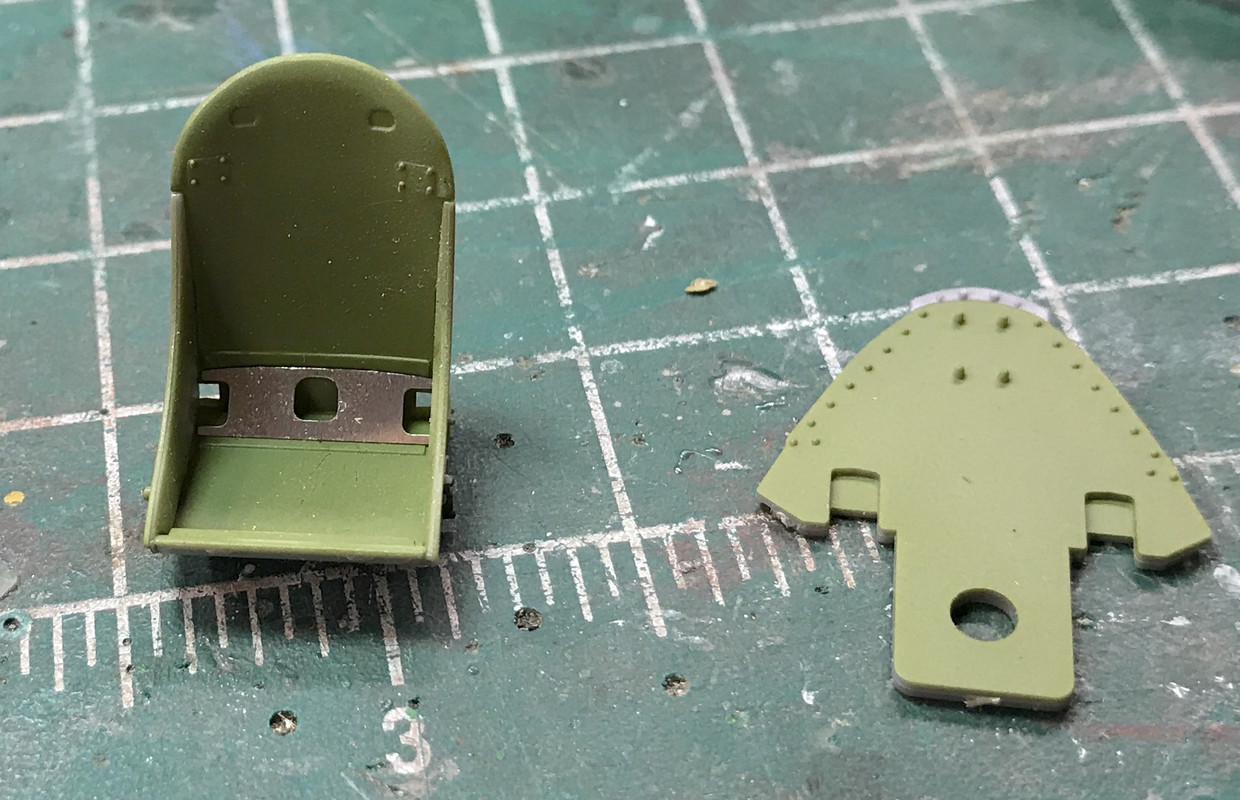
It started with building the seat. It's five plastic parts plue one PE. Unfortunately, the PE part is completely hidden with the seated pilot. 

I airbrushed all the interior green parts that were included up to this point plus the interior of the fuselage and some other bulkhead parts for the aft of the aircraft. As noted before, the engineering on this kit is exceptional. Where you have fit challenges with Trumpeter, this one is amazing. And being 1:32, you can pick out details that would be almost impossible in smaller scales. Case in point; the skull and cross-bones decal on the pilot's flight helmet, and a decal on the instrument panel.

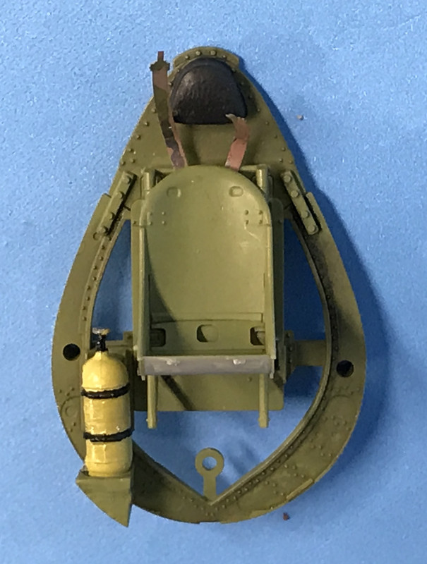
I glued the seat in place, and painted and installed the oxygen bottle. It called out semi-gloss black, but I painted it zinc-chromate yellow.

The underside of the seat is unpainted, but does not show at all. Getting the PE seat belt to stick using medium and thin CA was a challenge. It is VERY springy material and took more time than I would like to finally get it in place. All of the other PE seat belt material is not used when having a seated pilot. I also didn't put the wash on the seat since, that too, would be occulded by the pilot.

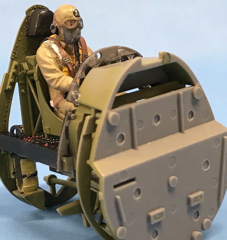
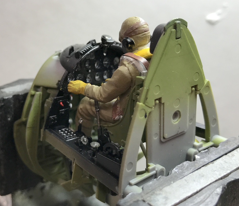
I glued the aft cockpit bulkhead in place trapping the control column and then, using thick CA, glued the pilot in place. Only then did I glue the right arm in place in such a way to grasp the control stick's handle. For this I used standard Testor's tube cement since it has some bulk and would fill any gaps between the arm and the body.

Now I had to get those pesky PE seat belts to join with the molded-on belts, which I now had to repaint from the white of the parachute seat belts to the dark tan of the cockpit seat belts since I didn't realize that some of the molded-in details were seat belts, not parachute belts. This was a wrinkle I wasn't expecting. 

The PE parts are probably stainless steel and are very difficult to shape. I tried to pre-bend them so the tension would be reduced a bit so the CA had a chance to hold them in place.

I scraped the paint off the pilot's seat belts so the CA had something to which to hold and then held them in place and hoped for the best. The first belt glued quickly, but the second was a different story. My experience with CA is if it doesn't glue the first time, any further attempts get worse. Each attempt had me scraping the cured CA off the plastic part so I wasn't putting new CA over old CA. Eventually it stuck and I repainted all the distubed areas.

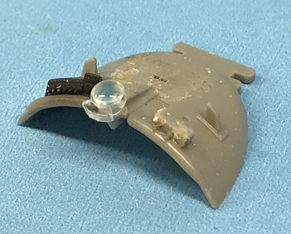
The instrument panel cowling had several small parts that glue to it before attaching to the instrument panel. Out of the five parts needed to be glued, I had two take off to the quantum rift: the little two-toggle panel on the right side and the clear gyro-stablized gun sight optic. Of the two, I finally found the clear part which would have been the worst one to lose, but couldn't find the little switch panel, so I scratch-built it out of piece of sprue and two pieces of high-E guitar string. I used a Xuron hard-wire cutter to cut small pieces of the piano wire, and if I need two pieces, I end up cutting 8 or more since they are microscopic and fly into the rift without warning.

After painting and assembly the panel looks okay. There is a conduit that comes out of a hole in the instrument panel and goes to the bottom of the gun sight that is not included in the kit. I attempted to make it out of a piece of wire insulation. It didn't work, couldn't really be seen, so I scraped the idea. 

I used some Microsol Liquid Mask on the gunsight's lens and airbrushed the cowl semi-gloss black, picked out the toggle switches with the Molotow Chrome Pen and then glued it to the cockpit assembly. My source book shows the leather front edge of the cowl to be a brown shade which I may paint tomorrow just to add more intereset.

With the addition of the canopy cowl, the interior is complete and ready to be installed in the fuselage. I notice that I've worn some black off his headphones that needs to be touched up.

The cockpit of this model was the singular most complex and complex cockpit model I've ever built, and believe me, I've built a ton of them. Tamiya is to be congratulated for doing it this way. In later versions of Corsairs, a cockpit floor was installed. It was a real pain when the pilot would drop something in the cockpit and it would end up on the bottom laying on the fuselage skin. It would be most difficult to retrieve something there. Kind of like fishing something out from between a car seat and a console. 

Next up: more interior fuselage stuff in preparation for joining the halves. Can't wait to build the engine... I love radials and this one's a beauty.

  • Member since
    March 2015
  • From: Streetsboro, Ohio
Posted by Toshi on Wednesday, October 31, 2018 9:44 PM

DMX512

Toshi

i hope you and Mrs. Toshi are doing well and each day gets a little better for you both.

TOSHI if you could have seen the hood hinges that Builder 2010 fabricated for a fellow modeler / hobby shop owner here in Louisville you would be floored.

I greatly admire the skill you both have aquired.


Thank you so very much for your kind words DMX512!  

On The Bench: Revell 1/48 B-25 Mitchell


Married to the most caring, loving, understanding, and beautiful wife in the world.  Mrs. Toshi


  • Member since
    May 2017
  • From: Denver, Colorado
Posted by MrStecks on Thursday, November 1, 2018 11:18 AM

Builder 2010

...when I noticed the other lens piece on the same fret as the first one that I cut out. Oh... sprue "P" and "Q" and on the same tree.

I've had that happen too.  I search and search for a missing sprue only to find there are several sections molded into one sprue.  Arghhh....

Your corsair is looking fantastic.  Great work in the cockpit, and the figure too.  I keep wanting to add figures into my builds, but always chicken out.

Cheers, Mark


On the bench:  Revel 1/48 B-25J Mitchell

In the queue: Tamiya 1/48 F4U-1A Corsair

  • Member since
    March 2012
  • From: Louisville, KY
Posted by Builder 2010 on Thursday, November 1, 2018 5:46 PM

Thanks! Tamiya includes nice figures. SWS has great figures too, but you have to order them on the after-market (+$$$).

Today was a milestone day: fuze joined. Before doing that there were a bunch of details that needed to be installed on one side or the other. In the aft portion, there were brackets, blocking pieces for the tailplane joining area, and four bulkheads and added details including the elevator bellcrank and actuating lever. Some of these pieces I had airbrushed on the sprue, but still had to hand paint some interior green to finish it all up. 

On the cockpit starboard (R) side there was an group of switch boxes held on a piece of flat PE with some CA. Two of the three pieces were dropped. I found one on the shelf at the bottom of my roll around work bench. The other was apparently gone and after I swept about 25 square feet I gave up. Then later, I see a little black speck at least 10 feet away and there it was. So I got all three installed and mounted to the fuze side. There's even the flare pistol which I painted exactly according to the plans plus wooden grips.

But... all of this wonderful detail is totally invisible as evidenced in the next group of pics.

Joining the fuselage was a joy! Even with all that stuff inside it just popped together. The seams are almost invisible. If any filler is needed, it will be very little. Then there were several panels that also fit perfectly. 

The cockpit opening is narrow (almost claustrophobic) and you can see almost nothing of all that fancy painting I did. I pity the guys that go the next step and run simulated wire runs to all the side switch boxes, also which will never be seen. The only seam that may need some work is the one immediately in front of the cockpit.

Here's looking up in the tail section. When the tail wheel and arresting gear are installed and then partially occluded by the gear doors, most of this won't show up either.

The last work I did today was paint the fire wall Tamiya Bare Metal Silver spray and install it. In this image you can see the beautiful fits on the front panels.

This same step had the exhaust pipes joined to the fire wall... at least 2/3 of the 6 pipes. The last two get installed just before the engine is mounted. I wanted to air brush them Tamiya Dark Iron as a base coat and needed to hold them. While the outlets are beautifully molded with the impression of an opening, I drilled them with a 0.032" drill and use some wire of the same size to hold them for paining. I will enlarge this hole just a tad to complete the illusion that these are, indeed, exhaust pipes.

After painting and weathering I will mount them to the firewall, which itself needs some weathering before the pipes go on. This model is moving along nicely.

Last night I gave the okay to laser cut my next model railroad building, so after the Corsair is built, I'll be back at railroad work.  

  • Member since
    October 2010
  • From: North west Wise county Texas
Posted by Pj's thunderbolt on Thursday, November 1, 2018 8:01 PM

its coming together and looks great.

Ole
  • Member since
    October 2018
  • From: Central VA
Posted by Ole on Saturday, November 3, 2018 11:06 AM

That looks great! Another kit on my short list. I'll be following this one.

  • Member since
    March 2012
  • From: Louisville, KY
Posted by Builder 2010 on Monday, November 5, 2018 5:26 PM

It's a great kit. Now I have my eye on either the Tamiya FB-VII DH Mosquito, or an SWS A-1H Skyraider. I have limited display space and I really need to build things with folded wings, which the Mossie has not. Either way, they're all fabulous models.

Went to the LHS to get some maintenance items: Tamiya masking tape, CA glue tips and some graduated plastic mixing cups. So I got to work around 2:30. Got the exhaust pipes air brushed and installed on the firewall.

Before installing the pipes, I dry-brushed some flat black and added some weathering powder to the sheet metal trough where the pipes exit. Then I air brushed the pipes Tamiya Dark Iron rubbed with some Rusty Brown weathering powder; not much, just enough to change the hue. And or course, you won't see anything but the tips which I painted flat black. I used my new Point Zero detail air brush for this. The nozzle is very fine and keeping it clean is not easy. There is another set that doesn't get installed until the engine is installed.

Instead of painting the engine parts separately, I sprayed/air brushed/brush painted all the ones that I could while still on the sprue. This pic shows the color selection. The cylinders are rattle-can sprayed Tamiya Bare Metal Silver. I then sprayed the intake pipes and pushrod tubes Tamiya Semi-gloss Black and the exhausts the same as the pipes on the firewall. I looked up the R-2800 on the web and saw that the gray can vary quite a bit. I took Tamiya Neutral Gray and added a lot of white and made a light gray. 

Some very fine details need to be picked out before removing the parts from the sprue such as the bottoms and tops of the push rod tubes are shiny, there is a black band around the bottom of the cylinder head to the lower cylinder, the valve covers are shinier than the cylinders, and then there's the provisions for spark plug wiring.

I have some Albion Metals very tiny brass tubing that is going to serve as the ends of the plug wires entering the cylinder heads. I used these the first time when detailing the wing fold area on the Avenger, so I'm comfortable cutting and handling it. It's best to cut it on some masking tape so the pieces stay where you cut them. You roll a sharp #11 blade back and forth to cut it. If you don't add any extra piping or wiring on a model, the least you can do it put the sparkplug wires on a 1:32 kit.

The lower cylinder has a slightly different cast than the heads, and all the fins need some seam treatment to set them off.

  • Member since
    March 2012
  • From: Louisville, KY
Posted by Builder 2010 on Tuesday, November 6, 2018 5:32 PM

My daughter asked my wife and me to help her do some election day canvassing and it was a beautiful Fall day here in the L'ville, so we did it for a couple of hours. It took away some of the stress of waiting for election results and gave us a chance to get some fresh air. But I did get to "work" on the Corsair at around 2:30 and got to work on detailing the R-2800 engine.

I started by drillig the spark plug locations on the front cylinder (part 5) using a 0.021" carbide bit which is the hole size to recieve the piece of small brass tubing for the spark plug wire. I also, drilled out the two lugs up near the valve covers which will be the mounting place for a cross-over tube, that I don't know what they do, but it's a neat detail to add. This is a photo of a 1:16 scale R-2800 model that was offered (built-up) by Fine Art Models a few years ago.

Here's another pic of the actual engine.

And here's another shot showing how the spark plug wires lead to the back of the front row and the other set to the back row. Notice, the wire goes through the black sheet metal shield (which the model includes) which completely obscures the plug connection to the back of the front row. So I'm not going to worry about any super-detailing anywhere but the front of the front row. Notice also that from the side of the cylinders all the way back there is another sheet metal shroud that directs airflow closely around the front cylinders and provides a more uninterrupted path to the rear cylinders. These shields are never provided in model engines. Modeling with wine bottle foil would be possible, but not necessarily useful.

The R-2800 has two distributors and two plugs per cylinder, not for system reduncdency, but to manage the flame front across the cylinder and prevent engine knock. By firing plugs on both sides of the hemispherical combustion chamber it precludes the flame front from compressing the charge to pre-ignition temp before you want it too. And, NO, Chrysler was the inventor of the Hemi...

After drillig the holes I tinted the fines starting with Brown Tamiya Panel Liner to color the lower cylinder area and Tamiya black liner for the head areas. I then hand painted that black connecting seal between the head and cylinder body.

The Albion Metals tubing I'm using for the spark plugs has a 0.021" O.D. and nicely accepts a 0.010" plug wire. To cut this tiny tubing I laid down a piece of double-sides Scotch tape and rolled a single-edged razor blade back and forth until the tube separated. The sticky tape contains the tiny tubing piece so it doesn't go into the quantum rift. I then threaded them onto a piece of high E guitar string so they wouldn't get lost.

Not only did the guitar string contain the parts, but it served as a guide to enable me to place the tubing over the hole in the engine and push the tubing in using a tweezers.

The only thing I didn't get right in putting the tubes in is some are in deeper than others. I should have had a gauge to stop the pushing at just the right moment. If I do it again, I'll do it different. Funny thing happened... I had a bunch of tubes cut and threaded onto the guitar string, but not at the back, up front. I had the string on the cutting pad arranged for a photo, when the string fell to the floor, and, of course, every single piece of tubing was launched into the rift never to be see again. So I had to cut a whole bunch more to take the new picture.

For the cross-tubes, I originally was going to use the brass wire I'm thinking about using for the ignition wiring, but it was too soft and couldn't hold shape. I measured the distance between the holes using the tapered jaw width of my ChannelLock long-nose pliers, and marked the jaw at the selected width. I then was able to bend many copies of high E guitar string (piano wire) to the hole spacing. I drilled these holes with the #86 (0.011") carbide and it was an expensive operation. These tiny drills are about $1.50 each and I broke three of them.

After inserting the wire I put a drop of thin CA at each hole to hold everything in.

  • Member since
    December 2002
  • From: Northern California
Posted by jeaton01 on Tuesday, November 6, 2018 5:53 PM

Nice work here, as usual.

The tubes are oil drains for the rocker shaft housings.  The two independant ignition systems surely have a effect on the flame front during ignition but the main reason is in fact redundancy. 

John

To see build logs for my models:  http://goldeneramodel.com/mymodels/mymodels.html


  • Member since
    August 2013
Posted by Jay Jay on Tuesday, November 6, 2018 6:03 PM

WOW  your engine detailing is amazing. TY for the W.I.P. on this as I want to build oneof these puppies and I'll use this as a referance if you don't mind.


 I'm finally retired. Now time I got, money I don't.

  • Member since
    March 2012
  • From: Louisville, KY
Posted by Builder 2010 on Tuesday, November 6, 2018 6:08 PM

I'll accept your input. I did read that the two sparks were essential for operational effeciency, but certainly redundency was equally as important. And I did find that in the R-2800 maintenance manual they're referred to as "Inner-Ear Drain Tube" which almost sounds comical.

Part of the reason I wanted to build this model is building this motor. And the cockpit. One of the real bummers about building UCAVs is no cockpit... Boring! They have landing gear, but otherwise, there's not much going on.

  • Member since
    March 2012
  • From: Louisville, KY
Posted by Builder 2010 on Wednesday, November 7, 2018 6:10 PM

One of my pictures yesterday was not an image of the Fine Arts Models r-2800. Instead, it is an image from a company that produces super-realistic 3D computer images. That firm is TurboSquib, an Internet-based company that offers very fine 3D models to the trade by various artists world-wide.

Today I almost finished installing the ignition wiring. I erred in not drilling the spark plug holes in the forward face of the back set of cylinders, since I now had to do it with the engine assembled.

I used the Molotow Chrome pen to pick out some bolt heads and the upper and lower clamps on the push rod tubes.

I assembled the engine starting with assembling the inter-connecting intake and exhaust pipes to the back of the forward bank. These are two-part affairs that are glued together and then you need to touch up the semi-gloss black of the intake tubes if you do what I did and airbrush the exhaust parts when they were on the sprue. Part of that piece is a section of the intake tube.

The rear cylinder bank went together very easily. Tamiya has been doing something that Trumpeter ought to learn. They connect the sprue gate to the rear of the part, not the side. There is no nub on the side that, when removed, can damage the part. Instead, the nub is on the rear gluing surface and is very easy to remove. To this rear bank I first installed the rear pushrod tubes, and then the rear engine case that has the intake tubes that exit from the supercharger housing. The rear engages with the front bank with a keyed inner ring and engages with the intake tubes that are coming from the front bank. When they do, the whole deal just pops together.

With the engine assembled I needed to prepare the ignition harness ring. This part is smaller and more frail than I would have liked. In fact, before I got it fully removed from the sprue it broke in half. I repaired this break by carefully drilling 0.021" to both ends of the break and CA'd it back together with a piece of same-sized phosphor bronze wire. I then had to drill the very small connection points (16) with the same sized drilled. Two wires eminate from each connection point. It was very dicey since the top of the connection point was wider than the little tube that connected it to the ring. Some of the holes went down the center, but a couple broke out of the side. I was almost going to plan B, by using and actual piece of copper wire to make this part, but I persisted with it.

For the wires, I chose 0.010" brass netting that was on the top of some Italian Montepulciano D'Abruzzi Tuscan wire. It was a twisted net with all the wires intertwined with each other. The two wires twisted together were 0.021" which is the same size as the holes I drilled and I actually wanted to use the twisted part too. 

To keep the twisted part from unraveling I soldered the twist just before it separates into the individual wiring. I was able to use the twisted part to anchor the wires into the holes in the ring and then captivate them using thin and medium CA plus a bit of accelerator.

I planned ahead with the cylinder head baffles by drilling the ignition wire pass-through holes before painting and separating them from their sprues. I then airbrushed them semi-gloss black and, when dry, glued them in place.

The rear wire for the front bank goes through the hole and then bends down out of sight. The front wire for the rear bank goes straight back to the plug since it's right in the middle of the cylinder facing you... although it's tricky to get the wire into the hole. The rear wire for the rear bank goes through its hole and drops down behind the cylinder. It could be belayed into the spark plug area in those cylinders if your inclined to insanity since it will be completely hidden by the cowl. Even if you use the transparent cowls included in the the US version of this kit you probably won't be able to resolve where these wires are ending up. Although if I have a cowl in an open position you might see this termination, so I may terminate those that would be seen.

Here are the first four wires in place. 

I got all but two wires in place before my session ended today. 

What still needs to be done is touching up the ring, the junction of the wires and the ring, the baffles (where the sprue connection was) and anything else that got worn. I'm also going to specifically paint the rocker covers a shinier metallic finish to differentiate them from the rest of the cylinders.

JOIN OUR COMMUNITY!

Our community is FREE to join. To participate you must either login or register for an account.

SEARCH FORUMS
FREE NEWSLETTER
By signing up you may also receive reader surveys and occasional special offers. We do not sell, rent or trade our email lists. View our Privacy Policy.