SEARCH FINESCALE.COM

Enter keywords or a search phrase below:

Rye Fields Sherman M4A3 76W HVSS with Full Interior: Start-to-Finish Build

23787 views
107 replies
1 rating 2 rating 3 rating 4 rating 5 rating
  • Member since
    November 2009
  • From: SW Virginia
Posted by Gamera on Wednesday, August 12, 2020 7:19 AM

Steady or not that's some impressive work! 

I've built transmission housings for M10s and M36s but nothing with that level of detail- wow! 

"I dream in fire but work in clay." -Arthur Machen


  • Member since
    March 2012
  • From: Louisville, KY
Posted by Builder 2010 on Wednesday, August 12, 2020 5:39 PM

I've been building kits since 1954 with a short hiatus during my late teen years (I even built while in college), and this kit is the most intricate plastic kit I've ever built. I'm viewing it as a nice challenge.

With little over an hour in the shop I got the "brass" painted on the fire bottles and built the gear case. While the gear case was not high in part count, it did present its challenges.

I mixed Tamiya Clear Yellow and a little bit of Clear Red. It's a bit orange, but won't be seen anyway. Remember: this was on a base coat of Molotow Chrome Pen.

While the gear case should have been a slam dunk, it was not. Instead of having the end plates inset into a rabbet around the edge like normal plastic companies do, they had both edges of the joint as a miter and little or no alignment aids. You have to get it aligned and started on one edge and then gradually position it around the perimeter. Solvent cement was applied from the inside and pulled through the length of the joint.

The gear covers on the ends were mislabeled in the instructions. Part E23 should have been E22 and vice versa. There were tiny alignment pins on both pieces that were on alternate sides. When I tried to put the parts called out in position, the two pins were direct opposing each other making it impossible to properly seat the part. When I looked at the other piece, the pins were on opposite sides helping align the joint. I made the change and noted it on the instructions.

The outer hubs slipped into poly cap and do rotate.

Underneath the cover goes the similar arrangement that you saw in the back, simulated welded on brackets holding a movable tow hook. Also note that tiny piece of plastic forming the guards on both sides.

Lastly there was part E6. When I first put it on according to the instructions, it seemed upside down. That's because it had the bolt detail facing the bottom and I thought it would be hidden when the gear case was joined to the hull front. So I reversed it with the bolts up. This idea was reinforced in my mind since there were matching bolts on the vertical surfaces of the gear case mating to the assembly.

Then I tried the whole assembly to the hull and found that the forward edge of the hull bottom had the bolts that I thought should be part of E6. Clearly, the instructions were right all along, so I ripped it off and re-glued it with the bolts facing down.

Here's where I had the bolts facing up... WRONG! You can see the vertical bolts that I assumed incorrectly had to match those on part E6. BTW: those bolted on bulges on either side of the foot board are the covers for the steering breaks. They're adjusted from the inside of the vehicle and are fully enclosed from the compartment.

Here's the part correctly installed and showing the bolts on the front face of the hull floor. The arrow is showing the bolt detail that is alread part of that flooring. So my concerns were unfounded. BTW: according to that gear box illustration on last night's post, the generator and it's drive system is painted black, not interior white like the rest of the trans. I'm painting the trans assembly BEFORE I glue it into the gear case and before that gear case is glued to the model's front.

As an aside, having an iPhone in my pocket to document all this work has so streamlined the ability to produce accurate build threads like this one. 10 years ago, taking the thousands of pictures that I have in creating these build stories would have been much, much harder. Imagine doing it when you only had film cameras. On average I take between 100 to 400 images per model that I document. This one is at 110 already and we're far from finished. The Typhoon took 124 and the Essex was 440. Technology is wonderful, ain't it!

I don't find it tedious to do this every day. I find it invigorating. It keeps me interested and helps me plan for future work. I thoroughly enjoy the interaction with many folks who I probably will never meet, and yet I have some who have followed my railroad build (now at 8 years) from the very beginning. I "know" these people and we share family stories and birthday wishes.

And one more thing: I've reduced my stress in finding these ridiculously tiny pieces that constantly keep responding to gravity and ending up on the floor. I bought a set of three LED utility lights for $15 on Costco's Impulse Aisle. I felt they could come in handy and they have. They're very bright. But this use I started doing yesterday. It lights the floor at such an angle that anything taller than a grain of sand now stands out. I used to try and use the iPhone's light for this purpose, but this Duracell baby really does the trick. Arrow is pointing to the tow hook bracket that I was searching for. It used to be when the floor was freshly painted that parts were easier to find. Now with all the paint spatter and other markings, it's getting harder. I really need to repaint...

  • Member since
    September 2013
  • From: San Antonio, Texas
Posted by Marcus McBean on Thursday, August 13, 2020 10:01 AM

Really been enjoying your build along with the trial and tribulations.  Have every thought of making a jewelers apron?  I made one out of an old pillow case, best thing I every did.  Great for catching parts I seem to drop all of the time.  Granted it won't catch everything but it I don't waste hours on a build looking for parts like I used to. 

Marcus Beer

  • Member since
    November 2009
  • From: SW Virginia
Posted by Gamera on Thursday, August 13, 2020 11:25 AM

Oh wow, that's incredible. Like Harold I hope you've got some way to display all this detail other than looking though the teenty tiny hatches. 

"I dream in fire but work in clay." -Arthur Machen


  • Member since
    October 2019
  • From: New Braunfels, Texas
Posted by Tanker-Builder on Thursday, August 13, 2020 11:57 AM

Hey! 

     Why are you tryin ta ruin me eyes? That'sa neat bunch of Widdy Biddy parts!

  • Member since
    March 2012
  • From: Louisville, KY
Posted by Builder 2010 on Thursday, August 13, 2020 10:20 PM

And as they say, "just wait, there's more!"

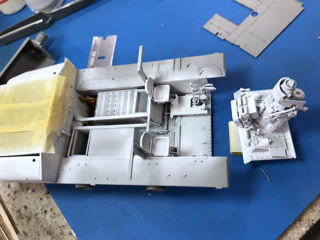
Continued building the interior with the Driver and Asst. Driver's seats. As per Ryefield's M.O., each seat was a complex assembly in itself with multiple little and sometimes ambiguous partrs. Notice that I subsitituted some guitar string with a Bondic end for the tiny, thin plastic seat adjusting lever.

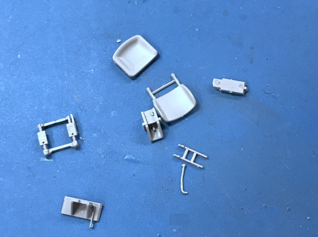
You assemble the parallelogram lift mechanism first which insludes some mock suspension springs molded into the plastic. And then you build the seat and connect the two. I drilled the mounting spots for the seat back to make the hole deeper and more pronounced. Remember when I commented about how small the alignment pins were? Just look at the two on the flat part on the right assembly that are supposed to engage in the two holes on the seat bottom. BTW: I had already opened those holes to ensure the pins find their mark. Gluing the scissor assembly to the base was a real hit-or-miss operation since there was not an apparent alignment guide.

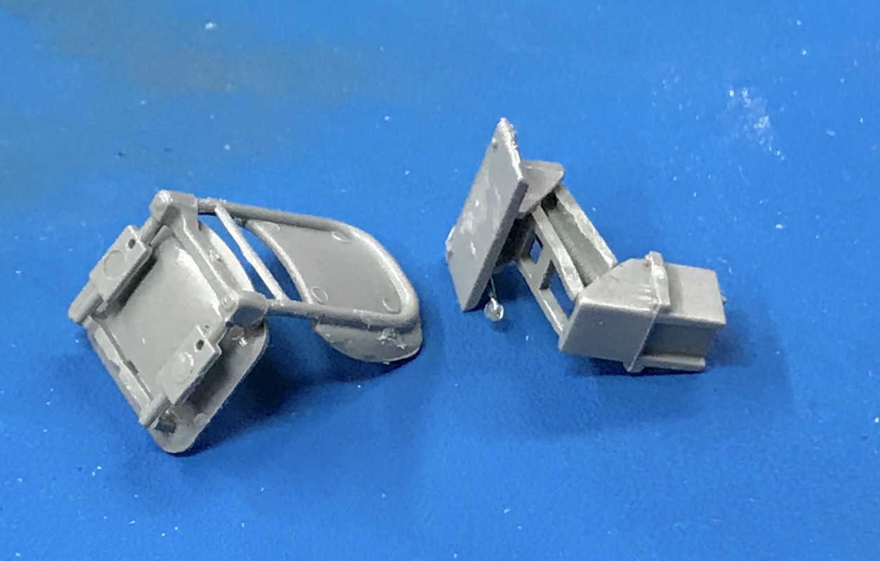
I glued the seat in place after they had a couple of hours to set up. They are very delicate. 

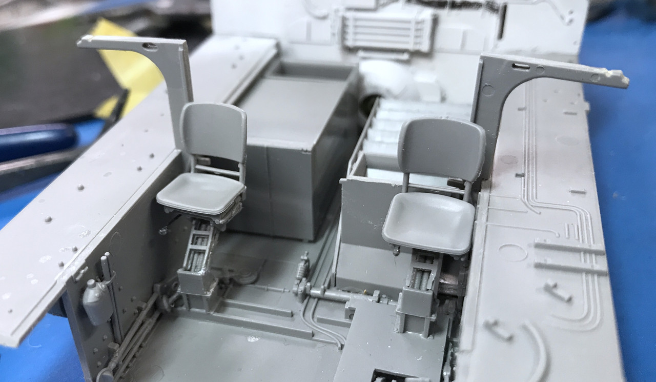
Behind the seats are other assemblies that go under the fighting floor, including the ready ammo rack, another ammo storage locker, an open-topped container, etc. Then there is a frame that supports the turret comparment subfloor. Only one of these things will be visible, the ready-ammo rack. These were sealed containers since this was the 76mm W for "wet" and they were filled with ethylene-glycol.

The frame was a very difficult piece to get settled in. One of the free ends in the back middle/right had a notch that was supposed to clip under the bar that was on the firewall, but just didn't want to go there so I clipped it off. 

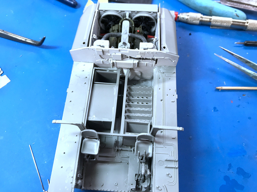
I re-installed the fire bottles in the back right corner. 

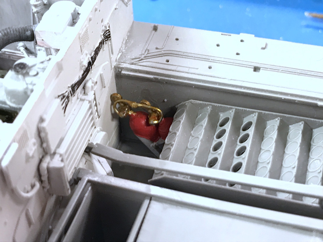
Incidnetally, that pipe rack thing on the firewall is the oil cooler, not a heating radiator. The air is drawn through the cooler fighting compartment by the main engine fans and exhausted out the back. By putting the cooler on the fighting compartment side would keep it much cooler than being in the engine bay.

It was time to paint some more white. I masked the engine compartment and stuffed some foam down the area where the fire bottles were since they were finish painted. I also wrapped a reversed loop of masking tape around my finger and stuck the trans assembly to it so I could airbrush that along with the rest. I only wanted to paint the drivers comparment and the fuel tanks that were also added that are now flanking the engine bay. I didn't worry about the sponsor tops. There are ton of detail that goes there and will be painted later. I just needed to get the lower parts painted before the floor goes in.

This is all that will be seen when the floor goes in.

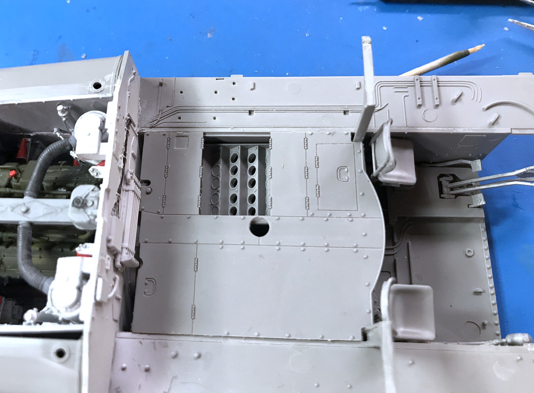
Do you see the fire bottles? Neither do I! Bummer! I have a choice to maybe open up the  hatches directly next to them so they're visible. It's my Sherman. I can do anything I want. The problem is that the doors that cover the ready-ammo locker, flop over the same area that the fire bottles are, thus blocking them anyway.

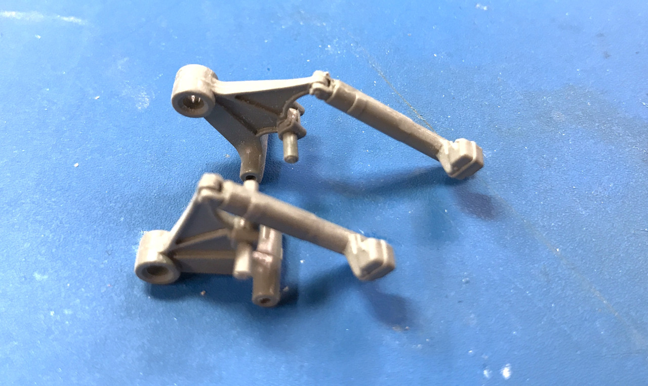
The instructions have starting to build the bogies. Lots of parts! And a bunch of silly parts. While many of you have built armor, I doubt that the bogies had this many parts. At least the ones I built didn't. The indidual swing arms have two parts. 

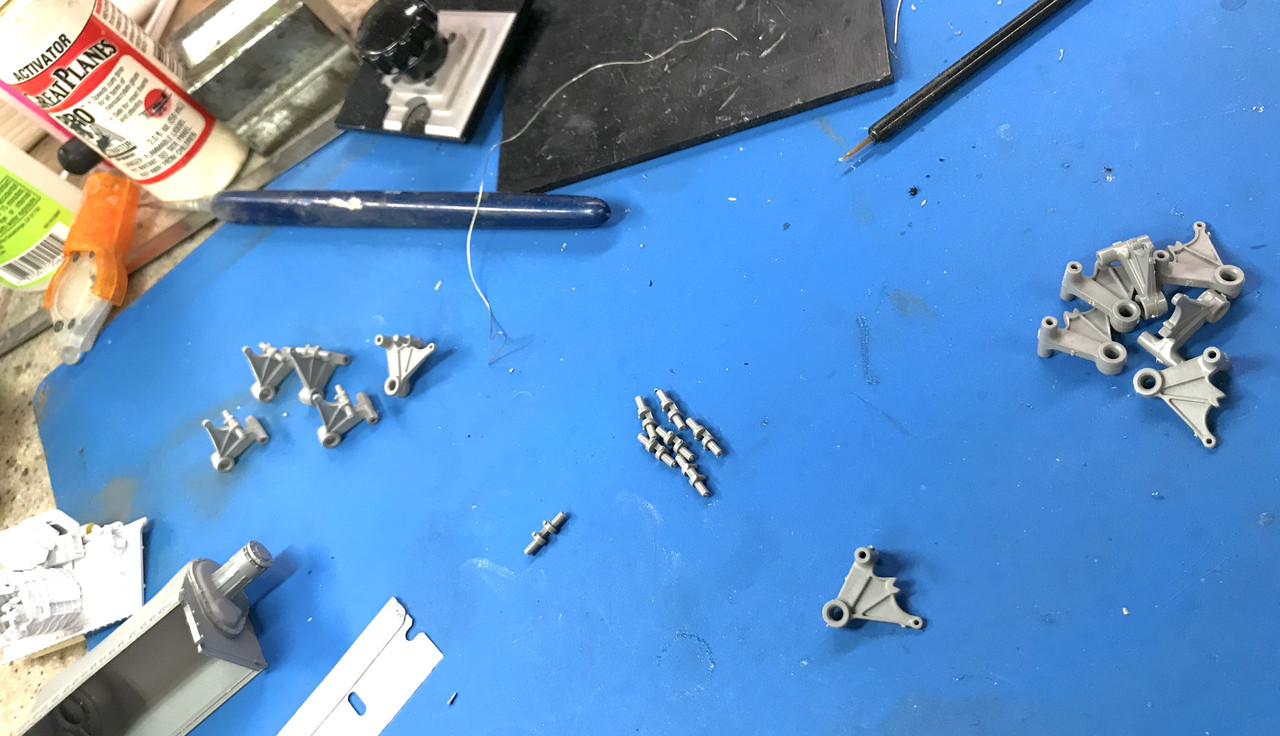
The little round part glues to a notch on the half-arms. Took a while to clean all the parts. No flash, just sprue nubs and some parting lines.

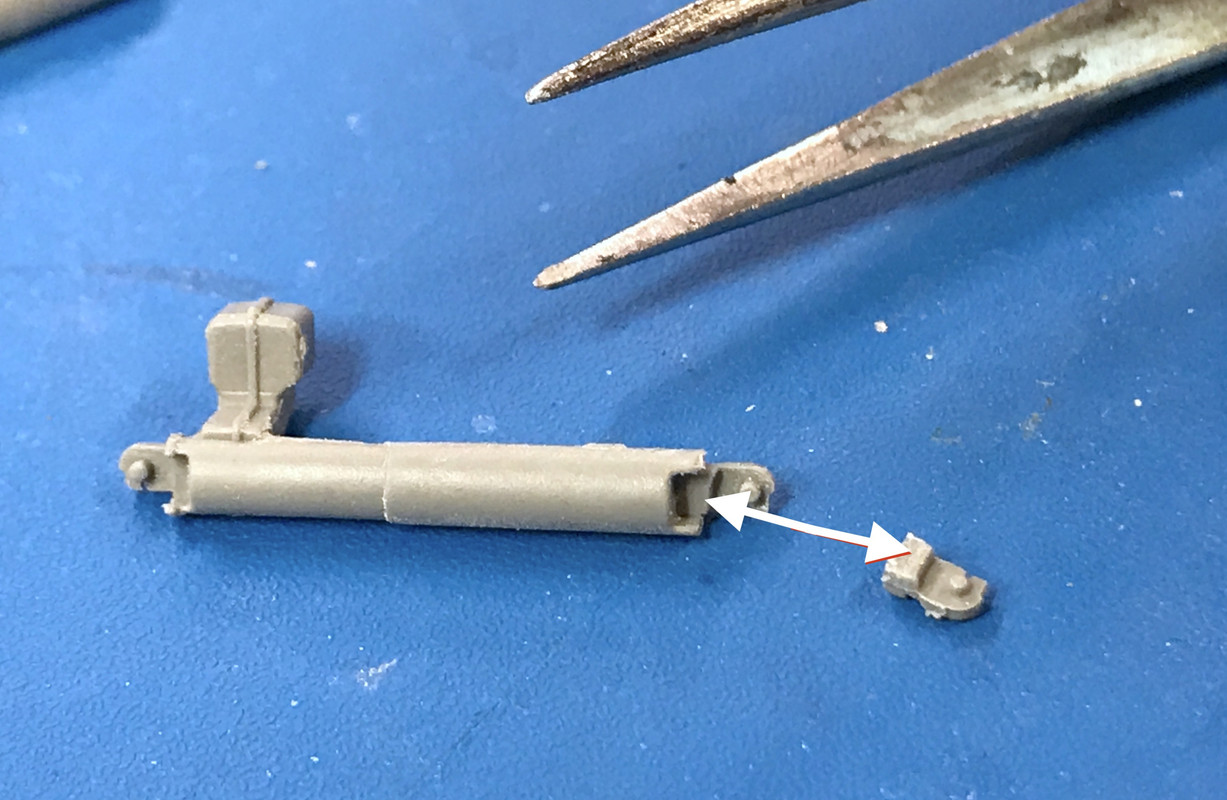
Then comes the shock absorber that is one of the members that holds the two sides together. The shock is three parts: the main shaft and two very little other halves of the two ends. These ends are supposed to be movable if you want the suspension to articulate. I was able to successfully get all of the part 58 (6) onto the one end and captivate the arm.

The arrow shows the notch that the part goes in. The part is laying upside down in the image. BTW: that very large tool in the picture is a very fine-pointed pair of Swiss tweezers. You can only get glue in the notch so the pivot remains free. That was not easy. And the gluing surface is small. The only way I could figure to get it together was to glue the part in place, spread them enough so they could pass over the pivot holes in the shaft and then squeeze them back together. Sounds simple, but it wasn't because the solvent cement would cure too quickly so when I spread them apart to slide them over the end, the little part would fall off. It wasn't too bad one the single arm.

Here are some completed first end connections.

Things have gotten much uglier when I attempted to add the second end and connect the two sides. Again the quick drying cement was causing trouble and I even had the first ends starting to come apart while I was manipulating the parts. And then I kept flying them all over the place as they launched at of those aforementioned tweezers. I'm now down two, hopefully I'll find them, but if not I'll figure something out. My guess if this was Tamiya, they'd made the clevis as part of the shaft and make it flexible enough to spread to snap over the end. Or it could be drilled and pinned. That may not work here because the ends don't have much meat and the holes will probably break out. If worse comes to worse, i could actually make them out of brass. Where there's a will...

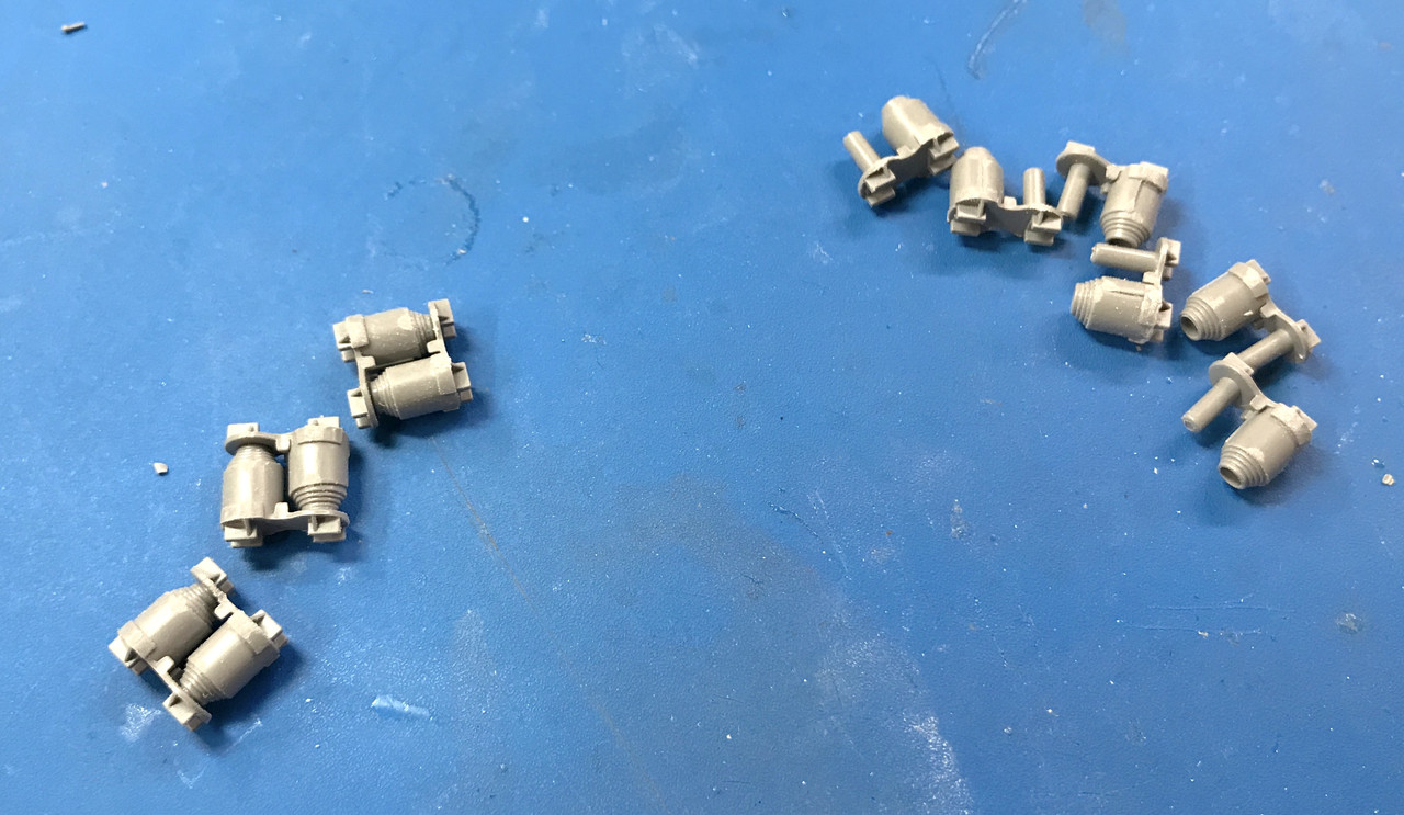
The easiest parts so far were the horizontal volute spring assemblies. These two identical parts just slip together. They don't actually expand and contract via the spring action. But they're not supposed to be glued to that cylindrical cross shaft and I'm not sure how they'll hold there. In the 1:1 Sherman, the springs are pushing outward with signifcant force.

I'll keep going on this tomorrow.

  • Member since
    November 2009
  • From: SW Virginia
Posted by Gamera on Friday, August 14, 2020 8:23 AM

Oh wow! That detail on the hull floor is incredible!

Again, my hat's off to you sir!!!  

"I dream in fire but work in clay." -Arthur Machen


  • Member since
    March 2012
  • From: Louisville, KY
Posted by Builder 2010 on Friday, August 14, 2020 9:36 AM

Thank you!

This is how Ryefield should have engineered this suspension part. The shock should have been split down the middle with a large pin on one side and a locating hole on the other. The glue surface would be huge and it would have been very easy to keep the glue out of the hinge zone. If Tamiya would have designed it, it would have looked like this. I'm going to flatten a larger area of the shock (it's in the back) and crearte a longer more substantial piece out of styrene and then use a steel pin. It will work better.

  • Member since
    November 2009
  • From: SW Virginia
Posted by Gamera on Friday, August 14, 2020 10:18 AM

As I remember the swing arms on the Asuka/Tasca M4 kit are designed more like that. 

"I dream in fire but work in clay." -Arthur Machen


  • Member since
    March 2012
  • From: Louisville, KY
Posted by Builder 2010 on Friday, August 14, 2020 7:32 PM

As you probably have surmised, when I set my mind to doing something, it probably gets done. I did get three out of the six bogie shocks built with the kit parts. And I found a way to glue the ends on with more success than I was having. 

I placed the tiny end in its slot and then held it in position trapping the suspension arm. I then add added a very small amount of solvent cement to the back of the end and continued holding the tweezers until the glue set. I had to add the glue with my left hand, which for you non-ambidexturous (spelling... this site does not access the MAC spell checker) that was a challenge in itself.

This technique worked well for the three ends that I had left. I was three ends short! That meant Plan B. I had to add a styrene end with phos-bronze rods to replicate the missing ends. This activity took most of the afternoon. It was not easy and it was not linear. The first attempt worked great, which gave me a false sense of accomplishment. The next two took almost an hour and half.

I made a micro-saw cut some distance back from the shock's end and then removed the material down to about half the diameter. I then cut a piece of 1/8" square Evergreen styrene, notched to fit into the cut on the shock. I glued this with solvent cement and let it dry.

The size of stock I was using was obviously oversized, so I used various methods to reduce the size and blend it into the existing shock strut. After shaping, I cut the slot for the existing suspension arm with two strategically spaced razor saw cuts. I then removed the piece between the cuts with the point of a very new #11 blade. The first attempt was perfect, although the slot wasn't quite deep enough and I had to fudge it a bit to get the suspension arm to sit deep enough in the slot. I then drilled the 0.022" hole through the clevis and tied the two parts together with the phos-bronze wire. 

Piece of cake... NOT! The second shock decided to rupture in half at the end of the flat cut due to putting too much stress on it when sanding the square styrene to make it round. This was another side trip. I drilled and reinforced the joint with the heavier 0.032" wire. It didn't come out perfectly straight. It will be noticeable.

Then I had one of the clevis ends let go due to being such a small cross section and when manhandling the wire to get it installed. This was not repairable and it meant ripping out the entire piece of styrene and starting over.

The other thing that happened was I cut the slot on the wrong axis not looking at the clevis on the other end. And then the other end clevises started letting go due to all the handling. They didn't break, luckily, but they were troublesome to get back together. To avoid overstressing them, I cut some relief notches in the suspension arm eye's edge to guide the pins so they could snap into positon with less pushing.

Finally, I was able to get all six bogie arms connected with shock absorbers. Their ends are different and a little fatter. If I attempt to reduce their size to the kit parts, the Evergreen styrene would have fallen apart. Evergreen's is a much softer composition and wouldn't hold up.

When painted they won't look too bad. Considering the alternative, meaning three incomplete bogies, I'm okay with the solution.

Then you have to attach these arms to the suspension frame that ties it to the hull. These elements were also 3-part affairs. More details. The flat backing was a single part, and the arm was another, in addition to that other part with the bolt heads.

Putting this all together was annoying. You had to put the volute spring into the crotch between the arms, but there do snap in. They just lay there. They're not supported until the swing arms are captivated by the frame. So you have to keep pressure on the arms pressing against the volute and then getting the pins on the frame into the arm holes. My first attempts were clumsy. Later I realized that if you hold the arms to their inner most position with you finger tips, then slide the frame up between the two lugs and get the pins in. Then you have to keep pressing them together while you put the end cap on that locks it all together. 

The cap goes on one way, so you need to orient it while doing all the other stuff. And you can't put too much pressure on the arms or the kit clevises will pop out from their location. Ask me how I know about that... After the cap is on, I put a tiny drop of cement  in the center of both sides being careful to not let it run into the hinge points.

I just took this picture. I went downstairs and took it. I also checked to see if the joints moved. NONE OF THEM DID! Not to worry, I was able to wiggle them back and forth, carefully, and got them moving. One of the kit clevises popped off, but I got it back together. I have two more to build and the bogies are ready for road wheels. To make this bogie truly operate like the original, in addition to the spring having to be compressible, the shock had to be able to telescope. I would be fun to make one that actually articulates as it should. Now these things only rock back and forth.

I also got the transmission details painted, but not weathered.

Y'all have a nice, safe weekend. Work will recommence on Monday.

  • Member since
    November 2009
  • From: SW Virginia
Posted by Gamera on Saturday, August 15, 2020 7:57 AM

Great job there on the bogies. 

Though I think I'd have given up on the working suspension and just cemented everything together. I mean once the model is attached to the base I'm never going to move the running gear again.

"I dream in fire but work in clay." -Arthur Machen


  • Member since
    March 2012
  • From: Louisville, KY
Posted by Builder 2010 on Monday, August 17, 2020 5:41 PM

Thanks! I did break down and fuse one of them where the shock end wasn't able to stay put. I'll put that in as a center bogie.

Short session: I had to prepare 24 road wheels by sanding off the sprue nubs and the parting line. I used this tool which I don't remember what it's called. It's very helpful in sanding round surfaces since it conforms to the curve and prevents flatening the shape. It loads up pretty fast. At first I was just wetting it, and then turned on the ultrasonic cleaner and immersed it for a few seconds to remove the swarth.

Next I prepared the wheels for painting the tires. I had to snip the ends off the round toothpicks so they penetrated deep enough into the axle hole to firmly grip each wheel.

I airbrushed Tamiya Rubber Black. Used some IPA and a few drops of Tamiya Retarder so it would flow better and not dry in the airbrush. I stuck the painted wheels into a chunk of floral foam which makes a very good gripping surface.

While this was drying I started making the masks to paint the wheel hubs. Instead of painting the hubs first and masking to paint the tires, I chose to paint the tires and mask to paint the hubs. It was easier to make a secure mask for the tire. I first measured the diameter with the digital calipers, divided that number in half and re-set the calipers to the new dimension, and then set the dividers to that number. My first attempt came out a little small. I then guesstimated the center point of the hub and adjusted the calipers to the wheel rim. I then kept slightly adjusting until the calipers perfectly circumscribed the rim's diameter. Tomorrow I will paint the hubs and the bogies, and then combine.

Rather than mess aorund with scaping paint off the bogies to prepare them to glue to the hull, I masked the bogie's glue surface. 

The bogies will be done tomorrow. After they're installed it's time for a tedious step: building the track from its 900 parts. There are 79 links per side (that's like 5.5 parts per link). I don't know how long this will take and it won't create a lot of interesting pictures, but hey... it's a tank and tracks, especially movable ones, are fundamental.

  • Member since
    March 2012
  • From: Louisville, KY
Posted by Builder 2010 on Tuesday, August 18, 2020 5:30 PM

In cleaning the floor looking for another part, I found the headlight assembly. I didn't even realize that it broke off. As I've been saying, Ryefield connecting points are very skimpy. I immediately drilled it for a pin and installed it with med. CA.

With that out of the way I spent the better part of an hour masking 24 road wheels 4 idler wheels parts and the glue area of the bogies. It's always this way. Masking takes a lot of time and the air brushing is over in minutes.

I used straight Tamiya Olive Drab for the first coat and then mixed a slightly lighter shade by adding some Tamiya Khaki to the O.D. This was air brushed also.

The first coat was Tamiya Rubber Black done yesterday. BTW: I sharpened on leg to a chisel edge on the dividers I use to cut the circular masks. This acts like a razor to cut the perfect circles. Periodically, I touch it up on a sharpening stone. You need to do this on a machinist dividers which have a screw adjustment. Otherwise it could easily change size during the operation. 

There's still some very minor touchup on the tires, but generally the road wheels came out very well. 

The idler wheels consisted of two halves and had a slightly larger diameter and hub so I needed to reset the dividers and cut those masks. They DID NOT have an alignment counterbore to keep the two halves in line when glung. I put them on a tooth pick to align them and added the liquid cement. I also used tooth picks for the bogies. The axle holes were just a little larger than the tooth picks so a couple of wraps with Tamiya Tape enlarged them so the parts were a nice tight slip fit. 

When the cement cured I slipped the idlers off the toothpicks.

To glue the road wheel axles you had to be careful to get the glue in the hole and not on the hub area. I put the axles in one side first, let it dry, then put them on the bench face down and placed the bogie over top, then I applied cement in the axle holes on the outer wheels and put the two together. I used my finest pointed Tamiya glue applicator to put the cement just in the hole. If any got on the outer surface I set that part aside and let it dry before re-gluing and installing. 

One of the axles broke without provocation. Really! I didn't do anything to it. I think the glue weakened the styrene. I drilled and pinned it (not shown). 

When all the bogies were assembled, I needed to paint the hull before installing. I had to entirely mask all the interior so I wouldn't wreck all that previous work. Like the road wheels I pre-coated rubber black, then O.D. and finally the highlight O.D. Masking again took much longer than painting.

I installed them on the hull. I noticed that the bogie brackets that were to join the hulls didn't form a perfect right angle. I don't know whether the bracket was out of square or the gluing up of the hull sides since all of these were separate parts. This made gluing less than optimum. I used tube cement to better fill the voids. Even so, two of them let go and had to be re-glued. It mess up my paint on the bottom a bit. I will touch that up later.

Here's the bottom paint. I didn't mask the return rollers. I was careful airbrushing so I didn't coat all their tires with black and where I did, I will brush paint later.

I gloss coated the trans assembly so I could effectively use Tamiya Panel Accent. I thinned the material with low-odor mineral spirits. The gloss prevents the accent from absorbing into the surface and gives more definition. The result was good. I painted the grease gun and the outlet vents. I then installed the trans assembly into the gear case and then the gear case to the hull. It's a shoe horn fit and requires manipulation. You need to be careful so you don't put stress on the rest of the very fragile hull assembly.

I picked out details on the control handles after gluing the control handle cranks to their respective locations. The tank now has steering. I stil have to paint the canteen and the 50 cal. tripod that's hung on the right side. And I have to paint the seats!

I masked the tail so the radiator outer is O.D and the inner remains haze gray.

So here are all the boggies in place. All the wheels rotate and the bogies do articulate.

Now that the gear case in on, I can install the drive sprockets and start working on the tracks. I just noticed, by complete randomness, I have all the bogies with the jerry-rigged shocks on one side and all the factory ones on the other. This side is the fixed one. You have to spend some time staring at it to see it.

  • Member since
    November 2009
  • From: SW Virginia
Posted by Gamera on Wednesday, August 19, 2020 9:49 AM

Oh wow, that's a pile of work but your results look spectacular! Heart

"I dream in fire but work in clay." -Arthur Machen


  • Member since
    March 2012
  • From: Louisville, KY
Posted by Builder 2010 on Wednesday, August 19, 2020 5:02 PM

It sure is, and the track work commenced today and Whoa!... It's a real pile of work. The first six-piece section took over an hour, but there was a learning curve. I'll walk you through it and explain.

They give you an assembly jig of sorts that holds the individual track pads. Instead of simplifying it as maybe they could, they made the left and right track pads separate pieces, but made the pivot pins and end caps on piece. The track pads lay in the jig very loosely. So loosely that I was constantly knocking them out of kilter when attempting to place the next piece. The link pins are connected to a piece of sprue that holds them in alignment.

You see the little divot in the back of the track pads? That's where the inner piece engages and captures the link pin part. You have to get cement ONLY on that little land if you want the track to move when built. That's tricky! When I started to glue the first inner piece in place, I was unsure if they were gluing in place since the pads below were still moving all over the place, and the sprue alignment piece was tipping them out of the jig due to its weight. I wasn't happy, so I cut off the alignment piece. BIG MISTAKE! The result was this.

The whole freaking thing went all over the place. Then things really went wrong! I started bebuilding it and then noticed that I had some of the links upside down. They not only have a right side up orientation. They also have a left-right orientation. I popped open the few glue joints that were completed and switched them around and glued all the rest of the inner pieces. The track moved. It was time to glue on the track alignment lugs in the middle. But where to they go? There didn't seem to be any place to glue them.

That was because I screwed up again! I have oriented all the links upside down. The correct way presents a little square notch in the middle where the alignment lugs go. Luckily, the glue hadn't cured hard yet. I was able to pry all the parts apart, reverse all the links and build it all for the third time. This excercise took almost an hour to build 6 links. There are 79 links needed per track. At that rate, I'd get the tracks done by Christmas... maybe.

Notice on the above that the pin ends have a dimple. This denotes the outside of the track. That means that after the first 79 links are make with one orientation, I have to have the presence of mind to reverse it for the next 79.

The second go around was much, much better. I had already solved one problem. The jig was also moving around. I fastened it down to the work surface with double-sided tape. I also did not remove the alignment sprue on the links. I also had confidence that I could glue the inner pieces carefully and still have flexibility. The second 6 links took about 10 minutes. That's more like it.

So now I have two whole track units. The tracks units are combined with another set of outer and inner track pads, but without the benefit of the jig. The jig has a top half which is supposed to align the lugs before they dry. I suppose it works, but I'm not so sure. The track seemed to get stuck in the upper part and to remove put too much stress for my liking.

And if the assembly wasn't tough enough, all those parts had to have their little sprue nubs removed. So far I only lost one inner track pad. If I was able to get my arms around this deal, I was prepared to buy an aftermarket set from Frulimodel or equivalent. So far, I sticking with it, now that I have it sort of figured out.

I got the seats painted and touched up any damage to yesterday's painting session.

  • Member since
    November 2009
  • From: SW Virginia
Posted by Gamera on Wednesday, August 19, 2020 8:04 PM

That gives me a headache just to look at it...

Asuka/Tasca's Korean War M4 has a somewhat simular track design but not as complex. And it's still a little too much for me. On a tank with tight tracks I'm happy with the 'rubber band' style.

"I dream in fire but work in clay." -Arthur Machen


  • Member since
    March 2012
  • From: Louisville, KY
Posted by Builder 2010 on Thursday, August 20, 2020 9:14 AM

The annoying thing is the prototype track was a single piece with the pins on both ends and the lock link on the ends. This is a much simpler way to build the tracks. The metal tracks are done this way. Instead, Ryefield uses five pieces per link. I can guarantee that some of those links are going to freeze due to some glue leakage. Hopefully none will fall on the curves. If murphy has his/her way, they most certainly will.

  • Member since
    February 2011
Posted by GreySnake on Thursday, August 20, 2020 10:42 AM
Very impressive work! The interior is coming along nicely and the OD on the outside of the hull looks really nice.
 
 
Those tracks look like a real headache to do. The Miniart workable T-51 tracks I built look simple in comparison to the Rye Field tracks.
  • Member since
    March 2012
  • From: Louisville, KY
Posted by Builder 2010 on Friday, August 21, 2020 9:12 AM

Thank you!

There's a silver lining... my local hobby shop, Scale Reproductions Inc. (one of the finest privately owned full-line hobby shops in the country) has a couple of separate Ryefield's track kits for the Sherman. So if I continually lose parts, which I am wont to do, I will have a source of additional parts to finish them. And I'm getting the hang of building them. Need a couple of shots of Bourbon to steady the hands real nice.

One of the members of the very fine Military Modelers Club of Louisvile (MMCL) is the technical director of the University of Louisville's Advanced Manufcaturing Institute. And he and I collaboratively designed a simple holder for my CA glue collection. I don't know about you, but those tall skinny bottle don't like to stand vertically. They're constantly tipping over and are a pain in the butt. This holder provides a slot for each of my normal CA's (Thin, Medium, and Thick) and the bottle of accelerator, which also is never where I want it.

We had three variations. The first was a two tier design with some angled supports. He simplified that to this cup design. Of them one has a solid bottom and the other is opened up. I chose to use the open-bottom version since I anticipate the bottles gluing themselves into the hole due to material on the outside of the bottle.

This little rack will make my work easier. It's all part of the ongoing "workplace optimizaton program" or WOP, that I'm undertaking to finally get my chaotic workspace under control. At the hobby shop yesterday I had my eye on the AFV Club Bradley Fighting Vehicle with TUSK armor and FULL INTERIOR. I'm really getting into this full-interior stuff. And my LHS owner can probably get the Ryefield Abrams with the full-interior. This will occur after I build this model and another major railroad project.

  • Member since
    December 2005
  • From: Goteborg / Sverige
Posted by Svenne Duva on Friday, August 21, 2020 10:03 AM

Hello Builder
Thank you very much for sharing your progress and the pros and cons on this build.

Have to admitt:
Bought the Typhoon before you started yours but you made me pick it up from the SOD.
Same with this build - My Dragon M4 is back on the table after +10 years in the twilight zone.

XLNT and most inspiring!
Keep them coming and late Good Wishes on your 75th!

Very Best Regards
Svenne

sic transit gloria mundi

  • Member since
    September 2018
  • From: Vancouver, Washington USA
Posted by Sergeant on Friday, August 21, 2020 3:04 PM

Gamera

That gives me a headache just to look at it...


Builder2010, I enjoy watching you work through the incredible detail in this kit, but like Gamera said it would give me a headache if I attempted to build this kit. I think it's safe to say this sets the bar at a new height for interior detail in a Sherman.

Harold


  • Member since
    March 2012
  • From: Louisville, KY
Posted by Builder 2010 on Friday, August 21, 2020 11:04 PM

Thanks! Yes... I suppose it does. Today I really got down to business on making the tracks. First I completely cleaned and reorganized the work area. I had a pile of miscellaneous crap on the left side, and more at the back and on the right as well. It made it hard to find little bits when they launched. I also put up a cardboard wall on the right size as a backstop to "catch" hyper-velocity little parts. I put quotes around "catch" because it's working more like a richochet board that reflects the projectiles to other unknown places. I hear them impact the cardboard, but then it's anybody's guess as to where they actually land.

I noticed in my picture of the lastest interior work that the angular support on the driver's side was no longer there. I didn't realize when it broke. I did find it on the floor. To repair it I reinforced the joint with a piece of 0.032" phos-bronze wire and some CA. The fracture zone was too small to just reglue it. Then all hell broke loose when I was working on the hull to fit that part. The front left bogie came off the tank! The little plastic part that glues to the bogie strut and the bogie then fell apart since this little piece is the key to keep it all together. To make matters worse, one of the pins that serves as the pivot point for the right swing arm was broken off in the swing arm. 

It took almost an hour to repair it all. I had to drill and pin the right arm pivot and then drill and pin the retaining plate itself since its glue joint was getting too munged up to be effective. The shock pivot on the left side (one of the kit hinges) kept separating. Each time that happened the volute spring would fall out. This happened over and over. I finally glued the volute to its resting places. This stabilized the assembly. It reduce mobility, but at this point mobility was the least of my worries. I was beginning to doubt if I could get it back together at all. Once it was stable, I could get the pinning done, got it all back together and touch up painted.

Then I got back to the tracks. I've got it down to a more fluid thoughtful process. I found that pre-staging everything made it go much faster. In fact, the fine cleaning of all the little bits took much longer than the assembly.

I found that supporting the sprue that has all the pivot rods kept it more level and made it easier to glue the inner tread pads, although it was holding it a little elevated. I eventurally went back to just letting it lie there while gluing in the first couple of inner tread pads. Once a few were in place, it stabilized. In this image you can see that the pivots are sitting a little proud of the right side tread pads (on the bottom).

I found that staging the inner pads so they all face sideways I was able to grab them in the right spot with the tweezers and get them in position quickly. The amount of liquid cement I'm using is very litte and it evaporates very quickly. If I fumble with the parts, but the time I get them in place there's not enough to hold the part. You have to be quick and precise. Often those two things are mutually exclusive.

Here's the caps lined up ready to glue in place. Remember: the glue can ONLY go on that little ridge with the open divot in it. If it runs down the side of the ridge it will get into the pivots and freeze the tread at that link.

I took another one of the jigs (there are four, one for each of the tread sprues) and removed the end lugs. Those lugs line up the upper part of the jig. This let me use it as an alignment jig for joining the 6-link track segments.

Joining the segments is easy with this method. I ended up fastening the jig to the table with double-sided tape so it wouldn't move around. You have to make sure you're fastening each segment in the proper orientation to the rest of the track.

I've completed 44 links so far. Each track requires 79 links. So I'm halfway to the first track. I think I'll be done the tracks by next Friday. They are getting faster. I did four this afternoon and that included fixing the that pesky bogie. The track is nicely flexible, but it's not very strong. In fact, I really wouldn't want to put any stress on it. I've already had some links break loose when the inner pad glue joint wasn't secure.

Everyone have a nice, safe weekend. See y'all on Monday.

  • Member since
    February 2011
Posted by GreySnake on Sunday, August 23, 2020 7:42 AM
Those tracks are coming out really nice. I can see how those tracks would be fragile once completed. I don’t envy you putting those on the model once completed.
  • Member since
    March 2012
  • From: Louisville, KY
Posted by Builder 2010 on Monday, August 24, 2020 6:09 PM

You ain't seen nothing yet. I finished track one today and started track 2. Several things occurred. I found one tread that was somehow reversed. I attempted, briefly, to break it and replace the shoes correctly, but quickly realized that I'm make that errant tread is not easily seen. 

Next, I produced all the links needed for track one. It needs 76 links.

Unfortunately, I overcounted by 7 links. So I made the track with the correct number. Then there's this: The instructions clearly show you create a full loop and lock it in place by adding the idler roller to pull the track in place AND use the eccentric to tighten the track properly, much like the real one.

Unfortunately, THIS DOESN'T WORK! The track won't fit over the return rollers. You can't get the darn thing in! You will break this fragile track if you try and force it. The only way to get the track on is to have it NOT CONNECTED. This is troublesome becasue of how tricky it is to install the top and bottom tread halves even when they're in the jig. Doing so when the tread is on the tank will not be fun.

Lastly, those 7 extra links can't be used on track 2 because they are backwards. The track is to be installed with the simulated hollow connector pins facing outwards, and the tread pattern needs to be consistent of both sides. I thought about breaking all the glue joints and reversing the treads, but quickly found out that the glue joints only let go when you don't want them to. If you want them to, you have to destroy the parts in the process.

I've gotten much faster building the track. I think I did 6 or 7 sets today. And I'm going to change my plan to not assembly any of the track to avoid the miscount from the first track. I'm going to produce the series of 6 links and when I get close to 76, I know exacly where I'm am. It's easier to count by 6s, than individual links.

  • Member since
    November 2009
  • From: SW Virginia
Posted by Gamera on Monday, August 24, 2020 6:45 PM

Oh gee friggin' whiz... Bang Head

Good luck with getting the tracks on there, I have no idea what to do. Looking forward to seeing how you solve this..

"I dream in fire but work in clay." -Arthur Machen


  • Member since
    March 2012
  • From: Louisville, KY
Posted by Builder 2010 on Wednesday, August 26, 2020 5:46 PM

Believe or not, the tracks are finished and two days before I said they would. I really did get into a groove and perfected all the little actions that streamlined the process. By not connecting the sub-groups until the end served two purposes: it gave them a chance to fully set before messing with them, and it was easy to count the number needed to complete. As it were, there were enough extra parts to complete both tracks AND have some pieces left over including all the pieces I lost and that extra chunk that I couldn't use. I believe the track is actually sized for the Jumbo Sherman which was a longer vehicle than this version. It worked out that 10 sets made the length. Even though 10 X 6 is only 66, there is one additional link between each set, so the total is actually 76.

In this image, all the segments are complete and I've cut and cleaned the tread parts needed to join the 10, 6-link sections which include the pins and center guides for the connnecting tread pieces, equalling. I cut 10 left and right outer treads and 20 inner treads. I actually only needed nine. The 10th will be used to loop the tracks.

So here are both tracks at 76 links per. Since there's one more link that joins them, it's actually 77. The instructions said make the length 76 links. I hope that they were talking about the track in the flat. Otherwise, I'll have to add two links. I have materials to do this. I bought the track kit, but thankfully don't need it. It was $20.00 and that's a lot of dough to spend if I only needed a handful of parts. It was a provisional buy and I'm glad I did it.

For the base coat, I airbrushed the track Tamiya Dark Iron. It's a very slightly metallic color and looks like a deep brown rust. I will add some more color in further operations. When this totally dry, I'm going to Dullcoat it to serve as a barrier for further treatment.

While this was drying I got to work on the next steps: assembling more details for the top of the sponsons. The tank has all kinds of storage compartments. One, which you can see, has three jerry cans for fuel. This is all for the right side except for that odd-looking thing that goes on the bulkhead in front of the left fuel tank. These get painted which initially and have some decals.

I also built the auxiliary power unit. There was a part that went on the front that got into the Rift so I faked it with a piece of styrene. This get's painted O.D.

Tomorrow is an exercise day so I'll have a shortened session. I will continue work on the tracks and then back to the interior details. I'm thinking of actually cutting away part of the turret to show the interior. I'm still thinking...

  • Member since
    November 2009
  • From: SW Virginia
Posted by Gamera on Wednesday, August 26, 2020 8:09 PM

Whew, that's a relief to hear the tracks went that well.

I like the idea of doing a cut-away. Not sure how I'd do it, looking forward to seeing what you come up with.

"I dream in fire but work in clay." -Arthur Machen


  • Member since
    March 2012
  • From: Louisville, KY
Posted by Builder 2010 on Thursday, August 27, 2020 6:01 PM

I won't have to cut away the hull since when the lid is off it's completely open. It's the turret that needs to be exposed. The turret has a top and bottom half. It also has interior walls. If I glue the two halves together including all those internal walls, I can then cut through both. There will be a gap between the inside and outside wall that should be filled to simulate the thickness of the turret armor. I would probably make the cut from the loaders side since there's more stuff on the walls on the commander side that would be sacrificed to make the opening. The other choice would be to just use the upper and lower parts separate, but you have to look up inside the upper half to see all the cool stuff and you'd be looking at the gun from the bottom, not the side.

All I got done on the tracks today was the Dullcoat layer, but I did do some stuff. I painted all those compartments that I glued together yesterday and built some more. I painted and installed the fire extinguisher that sits in front of the asst. driver. I applied some neat little decals and decaled the instrument panel. I also did some finicky little PE...is all PE finicky and little...just say'n.

There is one particularly complext compartment that has all kinds of stuff going on. It has a rack with what looks like machine gun ammo boxes. These boxes are a two-piece molding, but the spring clips that keep them in place when the tank is bouncing around are PE! There are 7 of them. They are folded 90° and glue to the back of the upper box. Again, those are really fine-pointed tweezers in that picture.

I used thick CA for gluing PE. I've discussed this before so I won't waste time here. To put these pieces on, I first positioned the part next to where it will finally reside, add a dot of CA and then slide the PE sideways until it seats properly. I went back over them with some thin CA to further secure these delicate pieces.

After gluing them in place I put a razor blade across of them and bent the forward lip up as it would be if it is a spring clamp. Notice also the folded PE shelf holding up that electrical looking device at the back.

If this wasn't enough there is more PE. This unit also holds PE brackets that support replacement black out headlamps. The lamps on the tank's front are clear lenses. The black out lenses were also carried on board. These and that relay device are painted O.D. along with all those ammo boxes.

Here are those cute little interior decals. I can drive this beast since the shift pattern is now clearly displayed on the generator shield. The others are name plate decals. You can see the fire extinguisher too. There's another relay device on the sponson that also gets painted O.D. which is why it's not white.

Lastly here's the instrument panel. Almost screwed this up just before I was quitting for the day. I decided to add another coat of MicroSol. And of course my brush caught a edge and turned the end under. I was able to pick it out sort of. This image was taken before that happened. I had gloss coated the panel before decaling. I will add some Bondic gloss to the guage faces. The kit's decals seem to be pretty good. They're not too thick and came off the backing quickly. More than I can say for the decals in the Airfix Typhoon. Those took 3 minutes or longer to break loose of the backing.

I think I may be able to get the tracks onto the return rollers without removing any guide lugs. I did a little experiment and think I can flex the sponsor lip just enough to get the track to go over the front roller. We'll see. Track and other detail work tomorrow.

  • Member since
    November 2009
  • From: SW Virginia
Posted by Gamera on Friday, August 28, 2020 11:36 AM

Oh that sounds cool! 

And again, great work there with the interior details. 

"I dream in fire but work in clay." -Arthur Machen


  • Member since
    March 2012
  • From: Louisville, KY
Posted by Builder 2010 on Friday, August 28, 2020 5:23 PM

Thanks! Today was a milestone day. The hull is done and I WAS able to get the tracks over the return rollers by flexing the sponson just enough to get it in. There really was no choice. There is not enough working room when the track is installed to connect it together using the complex arrangement it requires.

Before the floor pan could go in I had to install the ammo into the wet magazine. Because this was already painted, the gluing was more troublesome than it should be. For the brass color I airbrushed flat aluminum yesterday and overcoated it with Tamiya clear yellow today. It does a good job simulating metal to do it this way.

While most of them are just stub ends, the middle rows are full projectiles which they give you elaborate painting instructions and decals, and then you bury them into the magazine and never see all that work, so I didn't do it. You can see that I picked out the details needing O.D. painting. I painted those PE spring clips semi-gloss black just so they'd look different. I have no idea what color they really were.

I airbrushed the floor plan white and then went to pick out the panel lines. I did this after gluing the open hatches that would expose the magazine. I made a mistake of putting on the diluted panel accent (diluted with low-odor mineral spirits) which I thought would not dissolve the white since it's solvent-based. It did not, but the flat paint absorbs and spreads the accent where you don't want it. I removed it and then gloss coated the whole deal and went back and did the accent again. Then I hand brushed Tamiya clear flat to dull it done, but it was still too glossy so I shot it with Dullcoat. With the addition of the floor, the hull IS DONE!. This shows all the stuff on the right side.

And here's the view of the left side. I repainted the forward left section since there were some little parts that I didn't paint while, the first box of storage units looked terrible and the sponson itself was almost unpainted. I just masked around the area and kept the airbrush at a narrow stream. I have two airbrushes. I have my veteran (40 years old) Badger 150 which Badger reconditioned for free several years ago. And a fine line Badger 250 top feed for detail work. I seem to have lost the shift pattern decal... hmmm. I guess I won't be able to drive it now since I don't know where its gears are.

I had recently received the Kalmbach Armor Detailing book and learned that you can use pencil lead to create a worn surface for the inside running surface that contacts all the wheels. I first used A-K Interactive Real Metal paste to produce worn metallic surfaces on the center guides and the connecting links that make contact with the sprocket teeth. This is a wax-based paste that doesn't dissolve the paint beneath and can be polished. If you're familiar with Rub-n-Buff, this is very similar. It took a few minutes to apply the pencil. I then flipped the track over and added a bunch of brown weathering powder. I'm not sure just what effect it gave... I then highligted the grouser teeth with the same A-K product. I used a makeup sponge to just catch the tops of the tread. I like this effect a lot.

Here's one view.

An another;

I then fastened the ends together using pre-painted tread parts. This went well since I have literally hundreds of trials learning how to do it. I was able to carefully apply pressure to the sponsor just enough so the track passed the double return rollers and it was installed. I placed the idler wheels in the track, but ran out of time before putting in the idler shaft and the eccentric adjustment part to properly tension the track. That will wait for Monday.

Here's a nice front-end shot. This tank is mildly weathered so the track seems right to me. I'm not putting this on a diorama, but I may get some crew figures. I made some custom decals for a friend and he's getting MiniArt and Tamiya US WW2 tank crews for me.

The tracks are perfectly flexible and miraculously, the tank can actually move. We'll see how this works when the idler is on and there's more tension. So far so good.

Once the idler is on, I two paths to travel. I have to finish the exterior hull with the painting and adding some more details. And then there's the highly complex turret. I've looked at it regarding cutaway ideas, but still not sure how this will work.

JOIN OUR COMMUNITY!

Our community is FREE to join. To participate you must either login or register for an account.

SEARCH FORUMS
FREE NEWSLETTER
By signing up you may also receive reader surveys and occasional special offers. We do not sell, rent or trade our email lists. View our Privacy Policy.