SEARCH FINESCALE.COM

Enter keywords or a search phrase below:

Rye Fields Sherman M4A3 76W HVSS with Full Interior: Start-to-Finish Build

23785 views
107 replies
1 rating 2 rating 3 rating 4 rating 5 rating
  • Member since
    February 2011
Posted by GreySnake on Friday, August 28, 2020 9:16 PM
Amazing work! Those tracks came out really well and glad you were able to get the tracks on. The weathering on the tracks came out really well. The interior looks great as well. I’m interested to see how much work will go into the turret.
  • Member since
    April 2020
  • From: Central CT
Posted by xenon55 on Saturday, August 29, 2020 10:18 PM

Excellent work. I read your comment about the road wheels and this may help 


http://cs.finescale.com/fsm/tools_techniques_and_reference_materials/f/13/t/186174.aspx

  • Member since
    November 2009
  • From: SW Virginia
Posted by Gamera on Sunday, August 30, 2020 12:05 PM

Great to hear the hull is finished! 

And good luck with the tracks, they look good. 

Yes

"I dream in fire but work in clay." -Arthur Machen


  • Member since
    March 2012
  • From: Louisville, KY
Posted by Builder 2010 on Monday, August 31, 2020 6:15 PM

That's a good technique. I have lots of things that spin things including a Taig Micro-lathe. I will do that on my next tank... Possibly the Meng Bradley with TUSK and full interior. I'm really getting into this interior stuff.

Tracks are officially on. The spindle and eccentric adjuster are more fragile than I would like. It precludes heaving usage as a "toy" and relegates this to a static model. I did get the idlers in place and reasonably adjusted. Being thin and styrene, they just don't have the strength to handle too much manipulation. If they broke (and one almost did), I would machine a pair out of brass. Like I said, I have a Taig lathe and the correct holding devices that I could do it. Notice also I got the PE Headlight Brush Shields bent and in place. Not as easy as I would have wanted, but it's done and the upper hull can be painted inside and out. I will add the tools after the hull is painted so I can detail them all around.

For the upper hull to be actually positioned properly, that row of bolts on the gear case should overlap the row of holes on the hule glacis. They are not, and it's going to take a lot of forcing to get it together, which I ain't gonna do because I will break something. I'm not planning on gluing the upper hull down anyway. I'm not particularly happy glue PE edge-wise to the hull. The actually contact surface is negliable and should be more. I would have been nicer if slots would have been provided for the PE to enter. I bent the PE radius around a 1/4" drill. Close, but not perfect.

I started on the turret. Like the hull, every little tiny bit is there. The left and right inner walls are separate from the turret so they could properly mold the mounting holes on everything.


The reason for the limited progress today was due to not getting started until after 3:00. I was at the LHS (too long... I got the dickens for being indoors with others too long.) I will be glad when the virus is under control, like all of you.

  • Member since
    July 2014
  • From: Rifle, CO. USA
Posted by M1GarandFan on Monday, August 31, 2020 10:22 PM

Been following this build along with all the others and I can identify with some of the problems you've noted. I admire your perseverance and I'm sure it will be an outstanding build when done.

It seems to me that when you're done and find a time machine, you'll be able to go to work on the assembly line in 1943 and build M4's since you will have all the experience necessary.

  • Member since
    February 2011
Posted by GreySnake on Tuesday, September 1, 2020 11:41 AM
Glad you were able to get the tracks on. I’ probably be afraid to touch it now for fearing of breaking something now.
 
 
It’s really odd seeing a Sherman turret molded in multiple pieces.
  • Member since
    March 2012
  • From: Louisville, KY
Posted by Builder 2010 on Tuesday, September 1, 2020 6:28 PM

Thanks guys and for following along. Today I worked from after 1:00 to about 4:45. Of that three hours and 45 minutes, I'll bet I spent at least one hour of it on my hands and knees looking for lost parts. And that wasn't all. I needed to move the table (a drawing board screwed to an IKEA stool I made in Germany when living there) and knocked off a bottle of Tamiya Clear Smoke paint. Usually they bounce. This one fractured in half spilling about half of the paint onto the floor. My shop floor has been spilled on so many times it's looking like a Jackson Pollack painting. I emptied one of my smaller bottles used for the airbrush and cleaned it in the ultrasonic cleaner so I could salvage the remaining paint. The bottle came out spotless. Then I dropped it while wiping out the insides with a rag and it broke into smitereens. Then I found an old Tamiya Thinner bottle. I did the same drill again and this time didn't break anything else.

Speaking about full-size armor. From the Summer between freshman and sophmore years until my first year teaching I had the pleasure to work as a mechanical technician at American Electronic Labs (AEL). They manufactured military electronic countermeasure gear. I started as a rank amatuer and eventually was making experienced wages. It was great experience for me. One of the coolest things was the APC project. They received 15 brand new M-113 APCs into which they were going to create mobil jamming vehicles. It was a $4.5mm (1964 dollars) project and took three years to complete. The tanks were built by FMC. They were fully equipped regular M-113s. They even had the 50 cal in a crate inside. But this was not what AEL needed. They had to be completely stripped down to their bare aluminum. Yes! M-113s were made of welded 2" aluminum. So all the seats, hardware, everything had to be removed. This also meant air-chiseling all the little attachment brackets that line the walls for soldiers' gear.

It was a hot summer and the boss gave me the air chisel and told me to start breaking the welds to remove them. When the chisel hit the weld the entire vehicle rang like a bell and I was inside! It was intolerable. I told the boss this was not a job I was willing to do. He said okay and got a bunch of poor souls on manpower roles to do the work via per diem. We did provide jet muffs for them so they wouldn't go deaf. The boss was one of the best supervisors I ever worked for, and the team were some of the most clever and resourceful mechanical craftsman I've ever known. They could do absolutely anything.

But the best part of the gig was running the tanks. These tanks did not have any preservative in them so they needed to be "exercised" on a regular basis. AEL built a test track in the back lot and we all took turns driving them. They were very easy to handle and the steering levers is very intuitive. I got to do it once during my tenure.

The project was completed after my fourth summer. When I returned in summer 1968, the APCs were back. What happened? It turned out that they were so comprehensive and complex that they couldn't train operators in the 10 week cycle the military had. So they gave them back. We stripped out all the gear and AEL was using them in subsets mounted in standard equipment enclosures that would be mounted on trucks. 

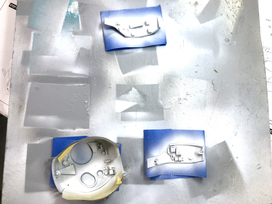
Okay, enough story telling. I got the upper turret painted and assembled and made a big dent in the gun. The gun body has 24 parts itself, not counting the 30 cal coax gun. There is a connecting link that was the elevating linkage, that if you include it, the gun will not elevate. I left it out since I want it to be movable. There are poly caps in the gun trunion to permit rotation so why not take advantage of it. 

I based painted the white on the upper turret parts before assmbling them. It made detail painting much easier.

I picked out all the little boxes and things. There are three canteens and a binocular box that I paint kahki. The canteen caps are semi-gloss black. I picked out the electrical wiring with better luck than I did on the hull. 

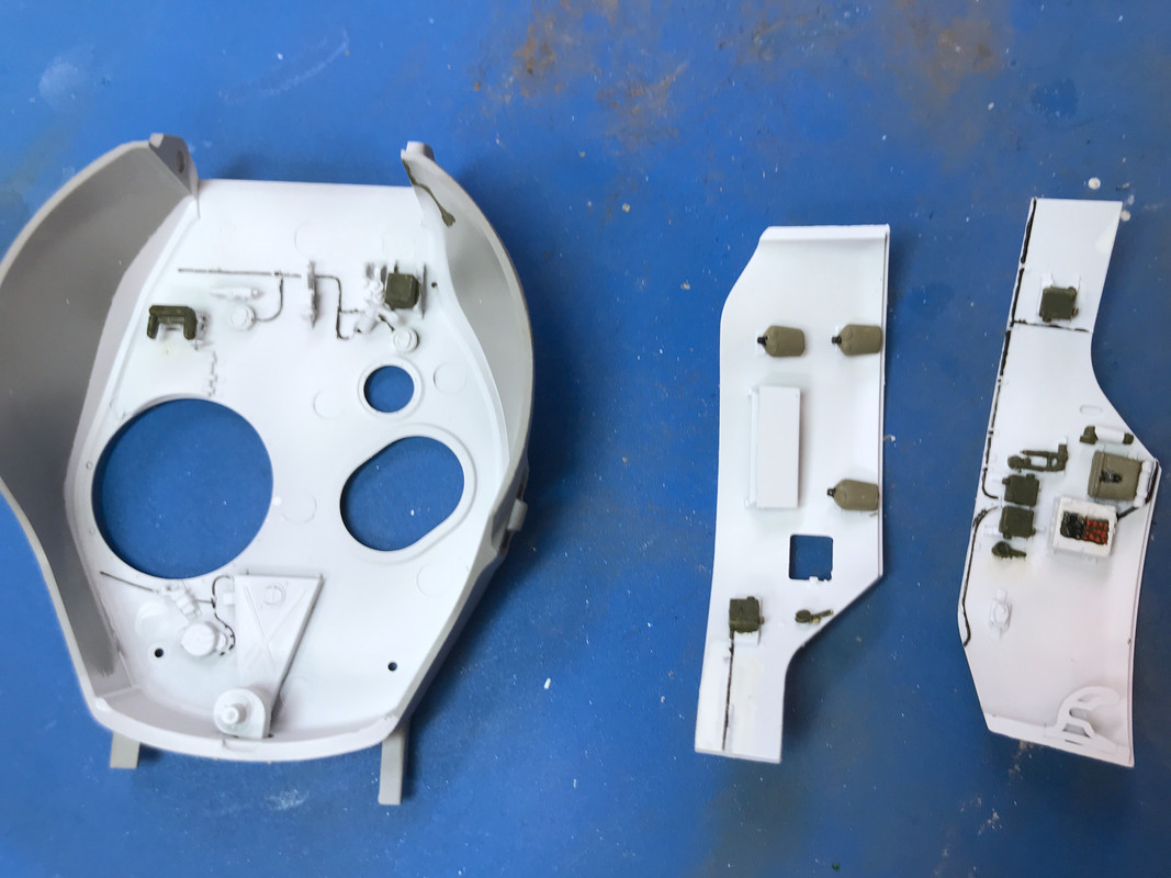
I was surpised that the commander's fixed periscope was not a clear part like the driver and asst driver's. I picked out the lenses of the overhead light fixtures with the Molotow Chrome Pen. 

I glued the side panels in with tube cement, again since it gives longer working time for large surfaces. I did a lot of back painting on all these little bits so everything came out clean. 

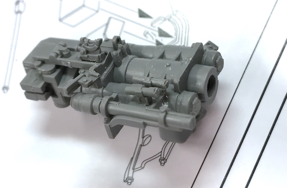
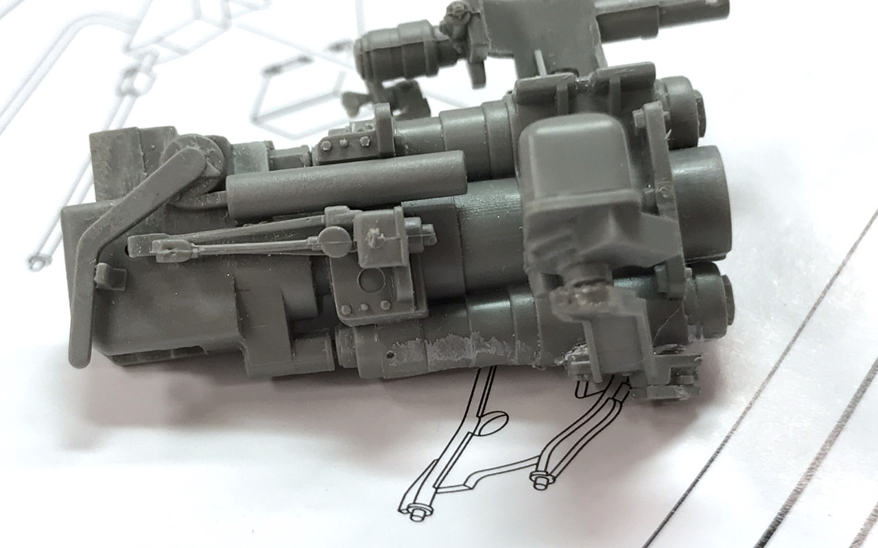
Onto the main gun. This is an enormously complex assembly. Many are delicate and require a lot of location testing to ensure their in the right spot. The recoil mechanism does work! Part G35 is this link I mentioned in the prolog. It connects to that clevis on the roof, but doing so would lock the gun since the rest of the linkage is non-working. I was looking forward to the gun build since I've always had a fascination with artillery pieces. 

When in Junior High School, the amazing Franklin Institute in Philly had a fully working model of, what looked like, a 5" deck gun from the WW1 era. It even had a step-thread break modeled. WW2 High Angle 5" guns had sliding wedge breach blocks not step thread. That model impressed me so that my friend and I found plans for it in the Institute's library. We had delusions of grandeur. We were going to build it as shop project. Of course we couldn't do it and the project never got out of the planning stage, but my interest remained. Only recently I found just how tricky it is to machine a step-thread breach. It's done on a special lathe that can engage the cutter for the short distances of each thread on each step. It's not something a kid's going to do in a junior high metal shop.

Here's a perfect example of a step-thread breach. This is the center 16" gun of number 2 turret of the USS New Jersey Iowa-Class BB. Very impressive indeed! The threads themselves do not seal against the blast pressure. That the job of the "Mushroom", the bulge in the breach plug center. The threads apply the tremendous pressure to hold the mushroom in place. As an aside (this post is full of asides...) if any of you ever saw Steven Segal's "Under Siege", the guns in that turret weren't real. Each Iowa gun was in its own "room". You can see the walls flanking the breach block. Each compartment is isolated from the other for obvious reasons. In the movie, the gun room was wide open. You can't make good movies in the rear Iowa turrets.

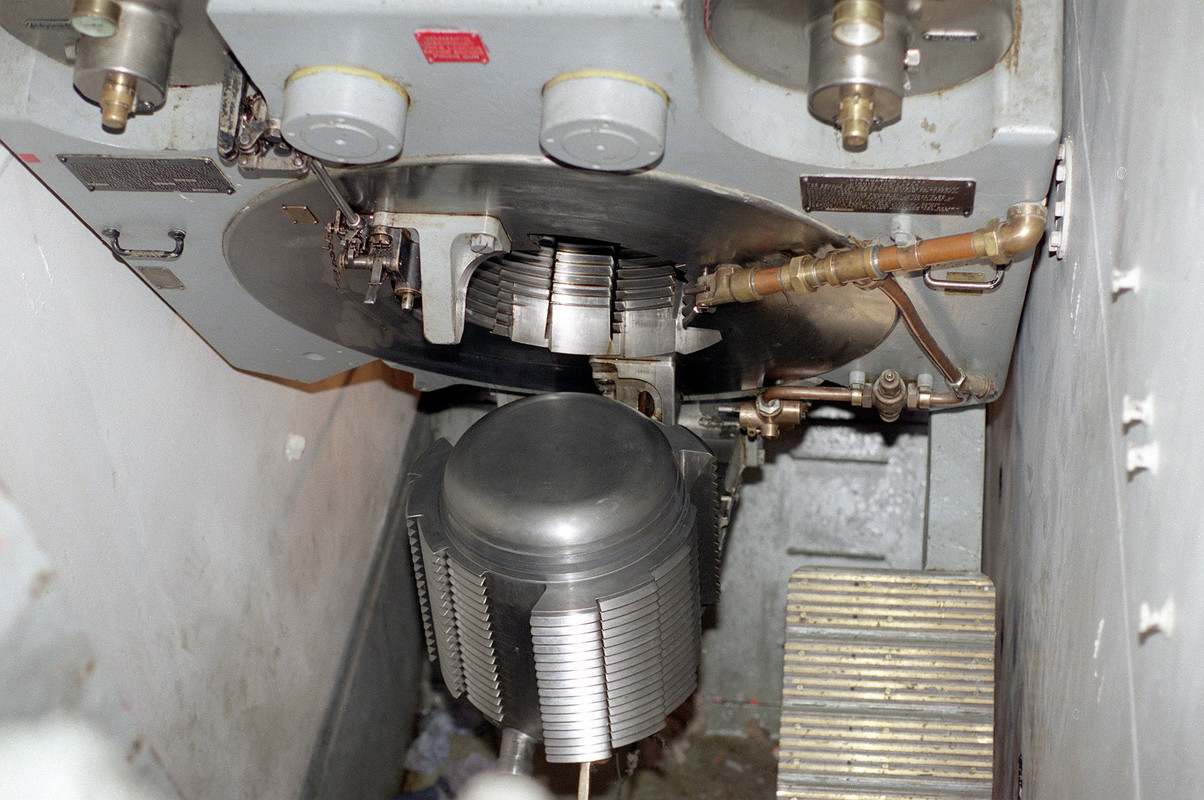
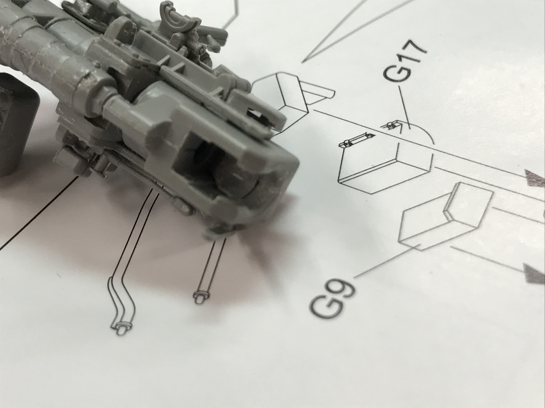
Tank guns are not step-thread breaches. They are sliding block affairs and the breach block iteself is in two parts for the model. If any other model would use one part for something, Ryefield is going to use three. This is the gun top. In the foreground is the optical sighting system. 76W Sherman's had a stabilized gun system and were the only one during the War.

Here's the bottom view.

And here's a view of the breach itself.

The Manlet went on next with its polycaps. The 30 cal coax gun is also built at this point. Again, it's a delicate, very detailed assembly. When I took this picture I hadn't glued on a diminuitive plate that connects the two prongs of the gun's mount to the mantlet cover. I had it in place, went to adjust it and launched it out of the tweezers. This was a high-velocity launch off to the right and I spent 20 minutes looking for it. Ended up making one which I didn't finish by the end of the session. I found a lot of parts (treads) that were lost days ago. They came out of the dimensional rift when this small part entered.

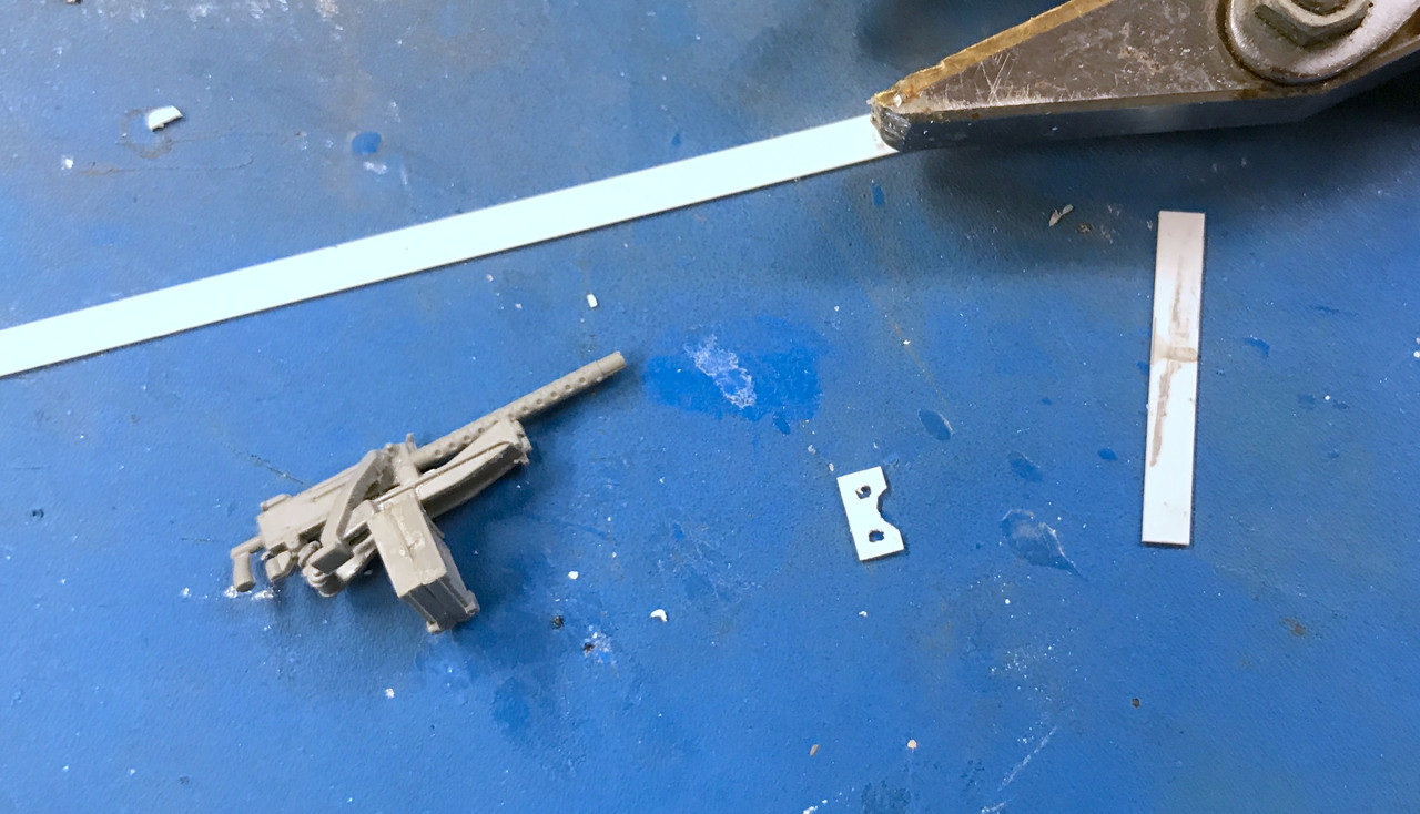
Hopefully, this styrene will be strong enough to do the job. The Ryefield styrene is pretty hard an tough. The Evergreen styrene is not. With all the fine parts I really haven't broken many. I've dropped and searched for many more than I've broken.

I now have a MiniArt WW2 US Army Tank Crew to go along with this model. Trouble is, they're all in poses outside of the tank. I wanted a driver and asst. driver for inside. I may have to do some kit bashing to get them to work. I looked at the Tamiya set, but all of the insde folks were half-bodies meant for tanks without interiors.

Tomorrow the guns get painted and then mounted into the upper turret.

  • Member since
    September 2018
  • From: Vancouver, Washington USA
Posted by Sergeant on Tuesday, September 1, 2020 9:10 PM

Builder2010, I have enjoyed watching you work through all the details in this kit and many times wanted to say 'I did that too' referring to tiny tiny parts that fly out of your tweezers or however they get launched into space.

After last Christmas I got really frustrated with dropping parts on a grey carpet floor and looking for them. I finally decided there has got to be a better way of controlling what's on my work bench.

I read an article online that another model builder had similar issues and he made two very simple suggestions that changed my life and saved me a lot of time on my hands and knees. First I taped a large white dish towel to the edge of my work bench top, so when I sit down the table cloth is over my lap like a skirt. It catches 90% of parts I drop or that fly out of my tweezers. The second thing I did is create an enclosed work area, that is to say I use my paint both as an assembly area when I'm not painting. This stops parts from going the other way and the LED lighting in the paint booth is much better on my eyes. As a last resort I get a lint roller and down on my hands and knees I go... I often find other parts I didn't even know I lost.

It's not fun getting old.

I agree with John (M1GarandFan) by the time you finish this project you will know every part of a Sherman tank.

Harold

  • Member since
    September 2018
  • From: Vancouver, Washington USA
Posted by Sergeant on Wednesday, September 2, 2020 12:36 PM

Builder 2010

I now have a MiniArt WW2 US Army Tank Crew to go along with this model. Trouble is, they're all in poses outside of the tank. I wanted a driver and asst. driver for inside. I may have to do some kit bashing to get them to work. I looked at the Tamiya set, but all of the insde folks were half-bodies meant for tanks without interiors.


Builder2010, I came across this kit of full body Sherman tank crew: https://www.scalemates.com/kits/nemrod-n35082-us-crew-sherman-europe-1944--223929

I don't know anything about Nemrod products. I did find one of these kits on eBay for $117.00. It must be a very rare find to charge that much money.

Harold

  • Member since
    March 2012
  • From: Louisville, KY
Posted by Builder 2010 on Wednesday, September 2, 2020 7:01 PM

Those look pretty good. Did a search for them and they cost around $40.00. They have the steering levers and seats already attached which is a small problem. The heads are the hardest thing to model in small figures. Since I have the MiniArt figures, I may be able to use their head and some body parts and sculpt the rest. We'll see. 

The dish towel idea is good. On my main work bench, I build a pull out tray with a curve cut out to go around my belly. I cover this tray with a white T-shirt. It worked pretty well when doing all the PE work on the Missouri and Essex. I should probably go back to working on it. Right now it's the overflow area for bottles of solvent, all the drills and on and on. I also like enclosing the whole space. Perhaps I can do it with cardboard with a clear acrylic roof to let more light in.

Very limited work time... had to do a ceiling touch up painting job after I went to the hardware store to have a paint chip matched. I got that front support remade for the 30 cal. coax. My first attempt looked like this.

This attempt had some holes to fit over the oval pins on the gun's supports. When I tried it in the space, it tried to push the gun further into the mantlet than it is supposed to go. That piece was 0.015" thick. I substituted another piece what was 0.040". This piece will work, but I had to let it dry overnight so it was a very good, strong joint. It will be stressed a bit. The thicker styrene makes up for the softer consistency of the Evergreen styrene.

I removed the pins and sanded the supports flat so I didn't have to worry about it.

This needs to be painted before assembling it the main gun part. I will be painting the gun assembly tomorrow or Friday.

  • Member since
    March 2012
  • From: Louisville, KY
Posted by Builder 2010 on Thursday, September 3, 2020 6:44 PM

Let it never be said that I don't follow the advice of the folks who read all my stuff. Before doing anything today I made up my mind to do something about the crawling around looking for tiny parts. While not a full enclosure, I've greatly cut down on the exit routes. I first added another piece of Masonite onto the right edge and then added significantly higher cardboard barriers. The parts can still escape vertically. If I enclose that I'll need to add more lighting. I have some LEDs that I could press into service. I'll have to decorate that cardboard with something... perhaps box art?

This view shows the attachment method. Again, I used SPAX star-drive screws with dress washers to hold the Masonite. White Duct Tape holds the cardboard which sits down flush with the work table on the inside making hiding places scarce. I also sealed the corner with duct tape on the inside to further elminate hiding places.

Then I took it further as Harold suggested. I installed a generous parts catcher that is stapled to the work surface underside and is ample enough to cover my entire lap. It already paid back the effort. When ladies used to wear full dresses they had automatic parts catchers in their laps.

This was created from some surgical field covering that my orthopedic surgeon son in law gave me years ago. Armed with this new environment I got back work.

I painted the gun receiver and recoil slide and the white on the coax gun. For the gun reciever, I airbrushed it flat white. For the slide and breach I airbrushed my "steel" mixture of flat aluminum and flat black. 

After painting the breach and slide, I treated the equilibrator slides to chrome adhesive foil and the gun slide to brushed aluminum Bare Metal Foil. The chrome foil was not a Bare Metal product. This really makes it pop!

Here's what the slide looks like inserted in the receiver body. Paint rarely simulates metal like real metal. I went over all the details that will need further painting with some Dullcoat to seal it and prevent the white undercoat from dissolving into the color. I also did this for the Coax since the gun is flat black and the ammo box is O.D. The gunner's telescope and other sighting aides are dark gray or black too.

This image attempts to show the insides of the breach area. There's really no way to view this when the tank is build I'm thinking, but it was fun to do. 

The breach interior was painted chrome silver and the breach block a combinaton of steel and silver depending if it was a wear surface or not.

I started to assemble the recoil shield assembly. It's a multi-part structure. Then trouble came. One of the very thin (0.026") styrene legs broke without any provocation. I immediately went about making a phos-bronze facsimilie. I had either 0.022 or 0.032 not the exact size so I went with the heavier. Fielder's choice...

After bending based up the measure of the plastic part, which I temporarily glued together so I could accurately note where the bends were, I filed the contact surface flat to increase the bonding surface and glue it to the plastic backing with med CA. I also had to drill out the mounting lug on the receiver to accept the larger diameter wire.

Later in the evening I went downstairs to do something unrelated to the model. I was cleaning something in the ultrasonic. While this was going on I went about cleaning up the other half of the guard and the other plastic leg broke off. DOH! These both broke in pretty much the same spot and I'm suspecting a molding flaw. In both cases, I did not stress the part. So tomorrow, I will make the other half too. Knowing that both were going to break, I would have made the entire assembly out of metal and soldered it together.

Luckily, I'll long since lost my anxiety about scratch-building anything so this too will work out okay. It's all part of the hobby as my wife always reminds me when I complain about somehting not working out in the shop. She defines "hobby" as a pursuit where you do what you choose to do. She defines "work" as a pursuit where someone else is telling you what to do. That someone else could be a boss, a customer or client. It's a pretty good definition.

  • Member since
    November 2009
  • From: SW Virginia
Posted by Gamera on Friday, September 4, 2020 8:49 AM

Great job there on the gun and turret interior!!! 

And cool story about the M113s, that musta been a blast! 


"I dream in fire but work in clay." -Arthur Machen


  • Member since
    March 2012
  • From: Louisville, KY
Posted by Builder 2010 on Saturday, September 5, 2020 12:43 PM

Thanks! It really was a unique experience. I was also taught how to climb a telephone pole using pole spikes. Not easy! As I said, these guys did everything. Besides being terrific mechanics and sheet metal workers, they also climbed up into the mast superstructures of warships to install antennas that were being tested. 

I got the recoil guard completed by fabricating the other broken rail, getting them all CA'd into position, and then joining the other styrene half to make the complete unit. I had to trim and finagle the fit becasue the added thickness of the Phos-bronze impinged on the joint.

I marked the extra metal that was protruding through the eyes with a Sharpie and then cut it off so the fit correctly. I did this off the model since there wasn't clearance for the cutters to do their job. Even if there was, I was afraid the shock would have fractured those, now-thinner-walled eyes.

There were some minor gaps that I filled with med. CA and accelerator, and then used Tamiya filler for the last bit of discontinuity. After sanding it smooth I airbrushed it white.

I dodged a bullet on this one. When those two rails broke I was dubious about getting this fixed correctly. All's well that ends well.

I installed the guard on the gun using thin CA to hold the metal rails and solvent glue for the plastic end. I was very lucky that the lugs held up even after enlarging the holes to accept the wire. If they had failed I would have rebuilt them with Bondic. Thankfully, that wasn't necessary.

After this was installed I attached the completed coax gun. The scratch-built pad was extending out from the side making it impossible to install into the mantlet trunion bearings, so I carefully ground it off with the Dremel and then filed it. I sprayed the entire assembly with Testor's Wet-Look Gloss in prep for detail painting and some minor weathering with accent liquids.

While the gloss was drying on the bottom side I started on the turret bottom. Like the upper half, this is a complete highly detailed assembly starting with the "sheet metal" (PE) ring gear guard. I don't know of any model that would have included this component. It was four parts of PE that needed to be specifically positioned in the ring's i.d. Here was the instructions depicting this.

It all starts with properly positionong the real ring so it coordinates with the drawing. I started by putting on the small pieces Y-2 and Y-56, to establish a good starting point. I then followed up with Y-1 and Y-55. I used thick CA. They curved nicely, and surprisingly, this step went really well. I was not anticipating that. On the long pieces I tacked one end with the CA and then worked my way around carefully putting some CA under the band as I went along. Here is the finished assembly. The two long pieces ended in a perfectly aligned butt joint meaning that I positioned them correctly. There were tiny locating pins (one per PE part) that supposedly guided the installation. I had to slice the last one off so they would settle down properly.

Next up was the large radio set. This was another multi-part job. Everything went along swimmingly until one of the tiny L-shaped grease gun-support-arms, twanged off of my tweezers. I thought I saw it go off to the right into my newly-protected area. So I searched and searched, but no joy. I finally scratch-built the part out of two pieces of styrene. I drilled a hole in the base piece so the small vertical piece had something upon which to glue. You're looking at the radio's bottom. Those two vertical brackets behind these supports are the only gluing surface to hold the radio to the turret. A little too scale for my liking. The radio gets painted O.D., but the supports, etc are white.

This whole effort took about 20 minutes. And then I was cleaning up the work space before shutting down for the weekend and then I see this; not to the right, but directly straight ahead. It may have hit the right-side backstop and ricocheted to this place. Who knows. All I know is, it was a dollar short and a day late.

The part twanged away when I was attempting to remove that very tiny sprue nub. That's a #11 blade tip in the image. This part is really small and I shouldn't have given a hoot about that nub. AMS rearing its ugly head again!

Have a nice weekend. Weather here in Louisville is spectacular for the Kentucky Derby, which for the first time, is being run on Labor Day Weekend and not the first Saturday in May. No audience, but that won't stop the betting. I had just written a political statement about potential clashes between protestors and armed militia, but erased it to keep my thread apolitical. 

Everyone have a safe, fun, socially distant, Labor Day celebration. The virus is not over! Don't let this holiday be a repeat of July 4th weekend.

My grandson's attending University of Illinois. The school is on lockdown after the students decided to not pay attention to the distancing rules and they now have 770 positive cases. My grandson's fraternity house suite mate just tested positive. My grandson tested negative. It's concerning. Young adults are notoriously careless about their personal safety thinking they are somehow immortal. They're not. Campuses all over the country are showing big spikes. They can do their classes virtually, but that doesn't stop the socializing. Heck... it was my favorite part of going to Michigan State (That and my R&B band). One college town has a 45% positivity rating. THAT'S THE ENTIRE TOWN! This virus is very, very contagious! Don't fool around.


  • Member since
    September 2018
  • From: Vancouver, Washington USA
Posted by Sergeant on Saturday, September 5, 2020 8:57 PM

Builder2010, I look forward to reading your posts and seeing how your mind works through all the challenges. You appear to be making good progress with a very difficult and highly technical build.

Below is a link to a picture of my workbench enclosure and lighting system. The only problem with this setup is I need to clear everything off in order to paint.

https://live.staticflickr.com/65535/49916591412_a8c9296d93_b.jpg

My wife and I left the heatwave behind yesterday on Friday. It has been in the mid 90's which is unusual for the Pacific Northwest in September. We arrived at our place on the Pacific coast about 100 miles from home where the temperature had dropped to 66 degrees with over cast sky. Later the clouds cleared and the temperature went up, but the humidity also went up to 76 degrees about 8:00 PM. These kind of weather fluctuations are not normal for this part of the country. I expected a lot of traffic with people heading to the coast for the holiday weekend, but was surprised to find nothing out of the ordinary.

Have a good holiday.

Harold

  • Member since
    March 2012
  • From: Louisville, KY
Posted by Builder 2010 on Sunday, September 6, 2020 10:12 AM

That is a terrific spray booth. It's the one appliance that I DON'T have in the shop and I need it. Not too bad when spraying acrylics, but I can't realy paint solvent-based in the house. The AC picks up the odor in the basement and quickly sends it upstairs.

Here's my latest design. It's a custom holder that I'm going to 3D print to hold MicroScale products (Microset and Microsol). These two are in those tall, light-weight plastic bottles that spill if you look at them the wrong way. I swear they sell product, not because people use it up putting on decals, but by spilling half of it. This is just the right size to get onto my printer. 

To be able to print it without a lot of supports in the tubes I chose to do it in two parts. I will glue them together after printing. I designed in a generous groove for gluing. I will either use CA or actually use the same resin as the part and cure it in the post cure UV box. In UV the gray resin is almost transparent so the light should (could) penetrate into the joint.

If anyone's interested, I can send the STL files to you via Dropbox. STLs tend to be big files.

  • Member since
    March 2012
  • From: Louisville, KY
Posted by Builder 2010 on Monday, September 7, 2020 6:28 PM

Happy Labor Day!

I labored in the shop.Smile I got the upper turret finished with the installation of the big gun and the elevation drive. I then started building up the lower turret and, as you'll see, ran into a problem, which I left unsolved at the end of the session.

Before installing the gun I did the weathering. I used thinned Tamiya Panel Accent Blank (with low-odor mineral spirits) and then wiped off a lot of the excess with Q-tips like I did in the hull. I added some silver paint to show wear on the recoil guards rods. I picked out the details such as the optical sight and other little bits. I painted the exterior end of the gun sight with Molotow Chrome over-coated with Tamiya Clear Green and ending with some Bondic UV-cured clear resin. You won't see much of this through the outer mantlet.

There was one more assembly that got glued into the upper turret: the elevating gear assembly. The bracket was installed earlier,  but now that the gun is installed the elevation hardware needed to go in. Tricky little deal and a great detail. This needs to be painted!

I wanted to get an idea of how much you'll see of this beautiful gun detail if the turret was installed, and it's not much. It makes it even more critical to NOT have the turret permenantly attached. BTW: the gun elevates beautifully!

I airbrushed the radio stand white and then brush-painted the radio O.D. I then picked out all the details and added some edge wear. The grease guns were subsequently painted flat black. These too will be hard to be visualized. Those brackets are very frail and I used some CA to further strengthen the gun/bracket joint.

The radio bench glued to the inner turret with just those two supports. Again, a fragile assembly. You don't want to drop this puppy!

Speaking of dropping, my newly modified work space worked like a charm. I dropped two parts and they neatly fell into the apron which I'm holding to my body with some clothes pins to further reduce the open areas for missile launch.

If my memory serves me, Mark Twain, had a passage in Huck Finn where he's dressed as a girl. He's helping a lady with some sewing and something dropped and he clomped his legs together to catch it. She immediately figured out his ruse since any lady of the day would simply let her dress' lap catch anything that fell. Only a guy would depend on his clomping reflexes to catch stuff. That is, unless you drop an Xacto knife, then you need to resist that reflex with all your might.

I glued the gear ring onto the turret bottom as per instructions. There is one very small alignment lug that is used to register this ring to the turret. I did my best to get it to key correctly. I then applied solvent cement around the perimeter to afix it.

There's a lot of stuff that gets attached to this ring. The most critical is the traverse gearing. This little assembly had 7 PARTS! It goes into a specific spot on the ring. In addition there were four other parts that went in.

The commander and loader's seats go in at this time. You could pose them up or down. I chose to have them deployed. I then attempted to fit the upper and lower turrets together. That's when the trouble reared its head. The traverse gear should fall behind the elevating gear IF the turret halves were properly aligned, but mine was impacting directly onto the elevating mechanism. In order for the gear to settle in properly, it had to be assembled as shown in these images.

The arrow shows how the two gear assemblies have to bypass one another.

But this is the way, the parts are aligned to get them to do that.

I pulled off the offending appliances to see if I glued them into the wrong slots. Nope! They're where they're supposed to be. All that's left is the ring itself is out of registration. It's almost an 1/8th inch out of alignment. I ran out of time today. Tomorrow, I will pry off the ring without destroying anything...hopefully... and re-glue it to the turret bottom in such a way to ensure that the gear is in the right location. As I said, the registation lug was very small. Considering how important this fit was, that lug shouldn't have been ambiguous in any way. That plastic wire coming from that electrical box has almost broken three times. It will break! And I will replace it with metal. That's not a prediction. That's a promise. Frankly, if were to do this again, I would leave off the PE gear shields. It adds very little in the realism realm and makes it very difficult to get good glue joints with all the parts hanging on that ring.

  • Member since
    September 2018
  • From: Vancouver, Washington USA
Posted by Sergeant on Monday, September 7, 2020 7:50 PM

Builder 2010

Happy Labor Day!

I airbrushed the radio stand white and then brush-painted the radio O.D. I then picked out all the details and added some edge wear.

Happy Labor Day to you Builder2010. You made significant progress today. I especially like what you did with the radio set. I was a Battalion Radio Sergeant during the Vietnam War, so I always look to see how modelers think a AFV radio should be painted and you did a first-class job.

I feel a little guilty reading about all your hard work while sitting around watching the ocean and drinking a glass of red wine. Maybe tomorrow I'll get something done?

Harold

  • Member since
    November 2009
  • From: SW Virginia
Posted by Gamera on Tuesday, September 8, 2020 10:19 AM

That looks fantastic Builder, I'd swear I were looking at the real thing. Good to see you made good use of your holiday. I got a lot done over the three day weekend too, a British tank crew and a F-51D. Best of luck getting the turret ring loose to re-cement.

Harold: Cool, glad to hear you had a great vacation. Looking forward to taking one myself. 

"I dream in fire but work in clay." -Arthur Machen


  • Member since
    March 2012
  • From: Louisville, KY
Posted by Builder 2010 on Tuesday, September 8, 2020 5:25 PM

Thanks guys! I really appreciated it! And never feel guilty. 

I woke up pre-visualizing breaking that glue joint and repositioning the ring. I was able to get the #11 almost all the way around without difficulty. The only place that required any coerxing was the training gear which had glued itself to both the lower and upper rings. I broke it loose without damaging anything. The long PE piece came off during this event, but I got it back on without complication. 

I glued the training gear back together and onto the lower ring, and then I positioned the ring on the lower turret and pivoted it until the alignment was correct, regardless of where that notch was. It turns out that the hand grenade case that hangs on the back of the ring is dead center at the rear of the turret. I marked with Sharpie in three places to keep the registration and then re-glued it with tube cement.

Here's how it all aligned now.

With the lower ring correctly assembled, which I would suggest you do before gluing. The notch isn't big and it's very easy to have it glue with the notch not engaged properly. Trying it on is a good idea.

After separating them again (they weren't glued yet) I installed another seat assembly. I painted the seats off the model. I also added some decals to the radio rack. I prep any decal areas with some Tamiya Gloss. 

The turret basket, like the rest of this model is highly detailed with small appliances that contain many parts. The gunner's control stand is one of those assemblies with 7 parts.

Another assembly was the ready ammo box and the gunner's seat.

A lot of stuff goes on the turret basket floor. I put an arrow to the small part that makes the gun go BOOM!

I may be wrong. I will have to do more research on this and re-watch "Fury" for the 3rd time.

I airbrushed the entire basket white, let it dry and before ending shot it with the high gloss in prep for the weathering and detail painting. There are some brass PE pieces to make the cartridge ends of that ammo look much better. The basket hangs from the turret ring with those two pieces of channel and the rails behind the control stand. These will be delicate. I did reinforce them with med CA and my pin then to the ring.

While the clear was drying I started work on the commanders cupola. Six vision blocks go into the lower ring and this gets glued into the outer ring. My new parts apron caught four out of 6 parts that headed to the floor today. Of the two that got away, one was found (a vision block-whew!) and a blocking cover for an turret antenna that doesn't go on this version. I will add the second antenna even though it's wrong... or I could easily scratch-build the cover I think as I write this.

Got all six in place without getting any glue on the optical surfaces.

This ring glues up into the outer cupola. After gluing I masked all the optics with Microscale Liquid Mask. It was too difficult to use making tape.

Onward and upward. Getting that turret ring fixed was a big deal. Getting it apart, repositioning it and gluing it correctly worked out as good as I could have expected. "Never give up, never surrender!" When the turret hatches are on, you'll even see less of the turret interior making it even more imperative to keep the turret entirely removable.

Editors Note: The firing triggers are the box in front of the pedal. The right button fires the main gun and the left the 30 cal. coax. The pistol grip on the stand is the traverse control. I'll pick out these buttons with red paint. The pistol grip appears to be black as do some of the other power equipment. 

  • Member since
    November 2009
  • From: SW Virginia
Posted by Gamera on Wednesday, September 9, 2020 7:32 AM

Glad to see you were able to remove and replace the turret ring without any problems. 

I love that interior, looks like Rye Field didn't leave anything out.  

"I dream in fire but work in clay." -Arthur Machen


  • Member since
    October 2019
  • From: New Braunfels, Texas
Posted by Tanker-Builder on Wednesday, September 9, 2020 8:01 AM

Hi;

 You are doing a great job. BUT, Knowing me, all I see after the fact is lots of greeblies for scratch building. Maybe it's worth the price just for that? I am not kidding. But all in it's proper place, your work on this beast is awesome!

  • Member since
    October 2019
  • From: New Braunfels, Texas
Posted by Tanker-Builder on Wednesday, September 9, 2020 8:04 AM

Hi

 This too; Do you have a Butchers supply shop nearby. It's actually more like a Restaurant supply house now. Get a Cook's apron and use that Then put some snaps on the bottom corners and snap to the table edge

  • Member since
    March 2012
  • From: Louisville, KY
Posted by Builder 2010 on Wednesday, September 9, 2020 5:17 PM

That's a good idea too. Right now the drape I'm using is working. I dropped two tiny PE parts and it caught them with no fuss. 

The Turret basket is fully detailed and installed in the lower turret. And the lower turret is glued to the upper turret. You really can't leave these two loose becasue it's a bit fussy getting them to key together and it would break stuff if you did it too often. At least having the turret removable would let you see all the cool stuff from underneath.

I attempted to use the little PE rings for the ends of the six cartridges in the "ready rounds" box, but they were such a pain to install (read that...failed!) that I used my chrome pen/clear yellow treatment to make them look metallic.

After looking a lot of interior images last night I saw that some of the appliances were not white and I altered the color-scheme to reflect this. The handgrip is the power traverse control.

It was time to glue this complicate thing to the turret bottom. Incidentally, the M4A3 76W was the only Sherman to have this truncated basket floor. It was necessary to access the magazine that was now below the floor. The turret had to be rotated to the proper position to open to that place. I imagine the loader would grab some rounds and put them in the ready box since once the turret was rotated, the magazine may not be accessible.

I didn't even think about using solvent cement to hold the three support posts to the ring edge. I went directly to medium CA and accelerator.

I then glued this whole deal to the turret top. And then I attempted to glue in the commanders seat. I can understand why they had you glue half of the seats supports to the bottom first, but frankly, getting it to settle into the hole in the top half seemed dubious to me, so I held off and put the seat in place when the turret was whole. It took a couple of tries and then I resorted to tube cement since the solvent stuff just wasn't cutting it. I inserted the seat through the commander's hatch opening. I tried from both directions, but this one was the best.

I kind of munged up the turret walls, but it actually makes it look more real (to me). This is a hugely enlarged image.

I took some shots looking into the various opening to see what you can see. Unfortunately, the iPhone camera can't resolve the contrast ratio that our eyes can. To expose the interior to see it, I had to expose the outside surface. You can see some things if you pay close attention. This is the right side of the gunner's station.

Here's looking through the loader's hatch and you can see the two firing switches.

Lastly here's as much as you can see of the main gun and the open ammo magazine lying below the floor pan.

The turret just plopped perfectly into position on the tank body. I was happily surprised to see the basket lug drop right through the hole in the floor. On the real tank, that lug contained the contacts and slip rings to get power to all the turret equipment while letting the hole thing rotate through 360°. It even cogs when you rotate it with the ring gear teeth actually providing some tactile feeling.

  • Member since
    March 2012
  • From: Louisville, KY
Posted by Builder 2010 on Thursday, September 10, 2020 6:07 PM

Before I get into tank production, I'd like to share a holder to prevent Microsol and Microset from constantly spilling. I drew this on SketchUp and printed it on my Elegoo Mars Resin 3D printer. The tubes and the base are separate parts which enabled me to print them with a minimal amount of supports. I grew the base traditional, on an angle with lots of supports on the bottom (actually the top since it prints upside down) and then printed the two tubes directly on the build plate with no supports at all. I designed a recess into the base that the tubes slipped into. I glued it together with the same resin from which is was created. The resin was cured in the UV Curing Box that I use to finish cure the objects. When objects come from a resin printer, they are about 3/4 cured. It took about 40 minutes to fully cure the object since the light had to penetrate deeply into the object. To 405nm UV the object almost appears transparent.

Here was the base as it came on the printer.

And here's the finished product.

No more spilled Microsol products. As I noted in an earlier post, I never use this stuff up, I always ended up spilling it. I resorted to clamping the bottles into a woodworkers vise to keep them upright. Now I don't have to worry about that.

I exercised today so my work time was curtailed a bit. I did work on the turret top details. The rotating periscope ring had the capability to actually rotate if you were nuts. I chose to glue it in the forward facing position. You were supposed to glue the inner periscope holder to the hatch only contacting a 1/64" wide PE ledge. You were supposed to captivate the PE ring with the holder and NOT get any glue on the hatch itself. It was fundamentally impossible. And this was the size of one of the separate detail pieces.

And notice too those tiny PE pieces supposedly being the clamps that hold the periscope in place. Ridiculous!

The loaders hatch also had provision to make it openable with a little plastic piece that captivated two little hinge pins. I was able to make this work. But, surprisingly, the commanders hatch itself DID NOT have provision for hinging. So I made it myself by cross-drilling and inserting a piece of 0.022" phos-bronze from both sides. The hatch now operates.

I added a couple more doodads on the turret top. I also filled the one seam that ran around the turret back with Tamiya Putty. The commanders hatch lid interior is probably O.D. like the front hatches so they don't flash white when opened, but the inside of the rest of the commander cupola would be which. I think the loader hatch too should be O.D. on both sides for the same reason. I also built the loaders periscope which gets glued in its own hole. Notice too the tiny PE angles on both sides of the loader's hatch. Looks like it could take a little tiny 1/35 Master Pad Lock. Cupola and Loader Periscope are not yet glue in.


  • Member since
    November 2009
  • From: SW Virginia
Posted by Gamera on Friday, September 11, 2020 10:05 AM

That's a good looking decal setting solution holder. I always brace mine in a box with the edge on one side and some tool on the other to keep them from flipping over. Your solution is much more elegant! 

And the detail there is incredible. If I were a surgeon or a watchmaker I might try to make the parts workable. But I'm not so I agree with you!!!


'Dammit Jim! I'm a modeler not a doctor!!!'  

"I dream in fire but work in clay." -Arthur Machen


  • Member since
    March 2012
  • From: Louisville, KY
Posted by Builder 2010 on Friday, September 11, 2020 6:11 PM

Today's session was two steps forward and one backward. I got all the interior painting on the upper hull done and brush painted the inside of the hatch lids O.D. or white depending on their use in getting ready to paint the exterior. I detail painted the periscopes with the bare metal sleeve and the O.D. heads. And I got all the rest of the doodads on the turret. 

You see that lift ring on the mantlet. That little SOB cost about 20 minutes of aggravation. Again, Ryefield doesn't provide a seriously deep pin hole or a reasonable pin to go into said hole. Therefore, I was wrestling with this little part until almost destraction. It keep rotating in my tweezers and getting stuck in the wrong position. Persistance paid off and I got it in place. As usual the second one went much faster. Incidentally, these rings were not to used to lift the turret, only to help to remove the gun from the tank. The movable hatches are closed, but not glued so I can open them after painting. At the turret rear are faux spring clamps that would be used to hold the 50 cal in its stowage position. I'm putting the gun deployed. They're also delicate details.

I forgot to photograph the inside of the hull and it's now fully masked for the exterior painting. 

Then there as a radiator guard system that hangs on the rear of the tank. This was another ridiculous assembly since the part is glued to only one edge at the rear and then is suspended with a single very thin plastic rod. I got the parts transposed since there is a left and right, and the notch to receive the rod was in the wrong position. I made a new notch. But in the constant handling of the tank, one of the tracks decided to shed those annoying tread pieces. I had to break the track apart, force off the idler wheel and get ready to rejoin it on Monday. It was a definite bummer!

In this picture you can see, the armored radiator guard (left side) the track and the little bits of tread pieces that I must now re-attach. Nothing broke, it just fell apart. I said before that the track assembly process is not very robust and here's a good example. The radiator shields also are supposed to glue onto the back place of the upper hull which would give them much more purchase and strengthen their attachment. But... and it's bit BUT, that would mean permanently attaching the upper hull to the lower and I'm not going to do that especially since I have provided no way to view the beautiful engine by gluing the engine covers in the closed position. They're just going to have to hang there and be delicate.

  • Member since
    November 2009
  • From: SW Virginia
Posted by Gamera on Sunday, September 13, 2020 7:47 PM

Ouch, looks like you've got things in hand though!

"I dream in fire but work in clay." -Arthur Machen


  • Member since
    March 2012
  • From: Louisville, KY
Posted by Builder 2010 on Monday, September 14, 2020 6:21 PM

I'm flattered by the confidence you have in my abilities. Hopefully, I won't disappoint.

I finished installing those pesky radiator shields. Since they're not going to be affixed to the upper hull, they were not stable. They're only glued on a thin line on their outside edges, and then there's that truss rod that goes to the lower hull rear plate. Without gluing to the upper hull they sagged downwards and inwads. I needed to cantilever them against one another and that required a 0.100" styrene spacer. With this glued to both shields, the truss rods and the edge glued, they became self-supporting. I also lost one of the truss rods and had to cobble one using some 0.022" phos-bronze rod. It's a minor detail and needed to be there for support.

Notice that I did get the track repaired and replaced on the tank, and then I lost another track pad. Unlike when I reconnected the track off the tank on the fixture, this time I had to replace the tread pieces on the tank since the other hald of the link was still intact. I was able to roll the track to a place where one of the road wheels was directly under the missing tread so I could put some pressure on the glue joint to set it. The first attempt I didn't hold the pressure long enough and the track separated on one side. The second try was successful and the tracks are one again fully intact.

From the top, these are just hollow plastic parts that don't make sense unless the upper hull is in place.

With this part in place, I was able to paint the upper surfaces. I started painting the NATO Black undercoat and then abruptly stopped. I hadn't masked the head and tail lights. I used MicroScale Liquid Mask to do this and then continued painting the black. The color dried quickly and I put on the next coat of regular Tamiya O.D. followed on with a coat of my aged O.D. mix (O.D. and Khaki) to highlight panels.

When dry, I glued the hatches in the open position. Prior to doing that I had to do some extensive work on those hatches. One of the periscope shields fractured and didn't respond well to re-gluing. I also lost one of the exterior hand grabs. I replaced the hand grab with phos bronze and replaced the destroyed periscope shield with one of the kit's PE ones. It actually took two to get it right. I brush-painted the damaged areas O.D. and then did the same to trim the edges of the hatch openings. I glued the hatches in with Med CA.

The paint looks okay. I had to brush paint the bearing race area of the turret since the masking was too severe. One of the reasons why gluing the upper hull on is counter-indicated is that fit at the gear case cover. The upper hull is supposed to slide under that row of bolts on the cover. It does not want to go and I'm afraid I would break something if it forced it. I took of some of the vision pieces masking, but not all. The turret's pieces are still masked, as are the fixed periscopes for the front crew. There are miniscule rear view mirrors that get mounted on a more miniscule PE bracked. I've left this off until last since it is sure to get whacked and broken.

I have to prepare and install all the tools and the tow cable, plus the extra tread pieces that go to the side of the upper hull. All the hatches will be open including the gun port on the turret side. It's not glued.

Tonight I'm going to design a set of display holders to show the upper hull and turret in positions so their undersides will be visible. I'm going to 3D print them. I almost hate to have to gloss coat all this beautifully flat paint so I can use panel accents. Can't use them on flat surfaces. There are also some more decals that need to go on. The end is near.

  • Member since
    February 2011
Posted by GreySnake on Tuesday, September 15, 2020 4:48 PM
The Sherman looks amazing! I’ll say all the work you’ve done on this kit has inspired me to finally finish my Dragon Sherman that’s been on the shelf since April.
  • Member since
    March 2012
  • From: Louisville, KY
Posted by Builder 2010 on Tuesday, September 15, 2020 5:37 PM

I'm glad I inspired you to get into action. I have a friend here in Louisville who's very active in community stuff. I said to him the other day that he's so busy doing good deeds and all I'm doing is working in the basement building stuff. He reminded me that all the articles I've written and the forums on which I am a very active contributor is affecting people positively too. I shouldn't sell myself short. So your comment reaffirms that belief.

I started today with building and installing the big gun. It doesn't get glued in. It's a press fit. There's a spring that goes in first and the gun and the receiver actually recoil. Before that it had to be assembled. There's the barrel, and the flash suppressor. The suppressor consist of four styrene and two PE parts. The PE is basically invisible as a series of two toothed rings that go between the front plate and a plastic ring. The back of the suppressor housing which simulates the muzzle end actually has some rifling grooves, but they too are really hard to see. I painted the gun while mounted in the turret and used more of the weathered O.D. on the top surfaces than the bottom simulating some mild fading.

Only one problem. When I tried the recoil it peeled the paint off the barrel at the slide end. I'll touch it up later. I did some research on these appliances and found their main function was to reduce the recoil by venting combustion gases out sideways. This was necessary to use the 76 mm higher velocity in the same turret. If it didn't have the suppressor the recoil would have pushed the gun too far back. This was one of the main limitations on simply installing larger and larger guns. 

I hand painted all the track tools while still on the sprue. I'll have to touch them up after installation to cover up the sprue nubs. These will need a little more work to make them really good.

I also took the time to paint the spare track links that flank the outer hull.

I built the 50 cal Browning. This was major assembly comprised of 17 parts. It is extremely delicate. I'm letting dry thoroughly overnight before painting.

This picture shows the separate trigger, hand holds and cocking lever. 

There's parts for several ways to mount this gun: on a tripod separate from the tank, in the pintle on the turret roof (as I'm going to do) and in separate pieces stowed in the clamps on the turret rear.

Here's the finished gun waiting for paint.

The fit in the pintle was a bit tight meaning I would have to apply too much unwanted pressure onto the delicate gun, so I checked the spindle size in a drill gauge and opened up the pintle with a #53 drill. It's now a nice slip fit.

I really haven't built many armor kits by the new manufacturers so even though I think this 50 cal had a ton of parts, it may be normal. You'll have to tell me. It seemed to be a bit excessive and this leads to it being really fragile.

Even the Jerry cans are a big deal. The kit has two distinct types and they have four parts each. One style has a small ridge around the top, the other is plain. And they have two different kinds of caps. The only thing in common was the handle and that too was separate.

The last thing I installed was the gun's travel lock (in the down position). Tomorrow I'll continue with adding these details Even the tow cable is a big deal being held to the tank with some micro-PE clips.

I also removed the liquid mask from all the transparents including head and tail lights and vision blocks. Regardless of my concerns with this kit's difficulty and crazy engineering, you have to give them credit for the mold accuracy. Notice that the "screws" holding in the vision blocks actually have clearly defined slots in them.

Till next time...

JOIN OUR COMMUNITY!

Our community is FREE to join. To participate you must either login or register for an account.

SEARCH FORUMS
FREE NEWSLETTER
By signing up you may also receive reader surveys and occasional special offers. We do not sell, rent or trade our email lists. View our Privacy Policy.