SEARCH FINESCALE.COM

Enter keywords or a search phrase below:

Sloop-of-war, PELICAN model scratch build.

9269 views
71 replies
1 rating 2 rating 3 rating 4 rating 5 rating
fox
  • Member since
    January 2007
  • From: Narvon, Pa.
Posted by fox on Wednesday, August 23, 2017 7:50 PM

You are doing some very fine work here Anthony! This is going to be a great looking ship.

Jim  Captain

 Main WIP: 

   On the Bench: Artesania Latina  (aka) Artists in the Latrine 1/75 Bluenose II

I keep hitting "escape", but I'm still here.

  • Member since
    August 2007
  • From: back country of SO-CAL, at the birth place of Naval Aviation
Posted by DUSTER on Tuesday, August 22, 2017 5:03 PM

I gladly join in the enjoyment of watching the ship come together. Most impressive and your explanations make the process understandable and interesting for me, an old plastic modeler.


Steve

Building the perfect model---just not quite yet  Confused

  • Member since
    December 2006
  • From: Jerome, Idaho, U.S.A.
Posted by crackers on Monday, August 21, 2017 11:14 PM

 The figurehead in place. Carving this item took plenty of patience with foul words in the background.

With hand carving chisesl, a rough outline of the figure was cut out following a pencil drawing on the rectangular stick. Then, the closer details followed by tools attached to my Dremel cordless drill. I prefer this drill, because there is not the problem of the power chore interferance.

Happy modeling     Crackers      Confused

Anthony V. Santos

  • Member since
    December 2006
  • From: Jerome, Idaho, U.S.A.
Posted by crackers on Monday, August 21, 2017 10:54 PM

The name PELICAN on the stern of the ship. The ring under the letter "I" is for towing the ship's boat during battle, so that the vessel will not be shot to pieces, or the crew will have an escape craft should the PELICAN be in a sinking condition. The scroll work is made by squeezing very soft and malleable wire under a vice. It took a number of frustrating tries before the desired results were accomplished.

 The name PELICAN was set by 1/8th" size transfer letters, which I happend to find at a stationery store years ago. I do not know where to find this size lettering here locally.The transfer is accomplished by placing the desired letter over the intended surface and rubbing that letter with a blunt pointed dowl. Scrubbing has to be very thorough, or else parts of the intended letter will come up missing.

Happy modeling    Crackers   Stick out tongue

Anthony V. Santos

  • Member since
    December 2006
  • From: Jerome, Idaho, U.S.A.
Posted by crackers on Friday, July 28, 2017 11:37 AM

Thanks Don for your reply. I take pictures with my Samson digital camera. Transfer the images to flicker gallery, where it is placed on the Finescale Modeler Furum.

Happy modeling       Crackers    Surprise

Anthony V. Santos

  • Member since
    November 2009
  • From: Twin Cities of Minnesota
Posted by Don Stauffer on Friday, July 28, 2017 11:16 AM

Wondering who you are posting your images with. A click on image properties brings up a URL with staticflicker.  Can you tell us more?

Don Stauffer in Minnesota

  • Member since
    December 2006
  • From: Jerome, Idaho, U.S.A.
Posted by crackers on Friday, July 28, 2017 12:56 AM

Carving the PELICAN's launch and rowboat took some carving skills from a block of wood.

These are the tools that were needed for the carving procedure. Ising the elongated stick, a pencil drawing was made on the stick the basic outline of the craft, as noted on the Hahn plans. Most of the hollowing out of the boat was accomplished with my cordless Dremel drill aided with wood carving gouges.

Here is the PELICAN launch from the side view and the bottom view. The extra piece of wood attached to the stern of the launch is a holding grip that was held while carving the vessel. The Dremel drill with carving attachments did most of the carving work.

The top view of the launch. The right hand side of the picture is the paper ribs with a 10 mesh plastic canvas grating for the floor bottom of the launch. The penny denotes the scale of the carved launch.

  l

The hollowed out launch to be and the completed version at right. The penney is for scale.

The completed launch with the attached rowboat. The rowboat was the more difficult task, because of its small size after three attempts of carving. The determination of the depth of carving on both crafts was by holding the carving close to a naked light bulb. The brighter of the light shine through the carving indicated how close it would be to puncture through the wood.

To be continued.

Happy modeling     Crackers     Cool


Anthony V. Santos

  • Member since
    December 2006
  • From: Jerome, Idaho, U.S.A.
Posted by crackers on Monday, July 24, 2017 9:10 PM

Thank you CapnMac82 on your explanation of the position of the capstan on the PELICAN model. On this warship model by Dan Holmes, the capstan is visable without protuding deck furniture obstruction. The grating can be walked on as long as crew members did not stub their toes as they trod across this deck feature.  Ship builders were practicable people by constructing common sense things, especially on warships, where efficiency was a necessity, especially during battle. When viewing the Harold Hahn plans of the PELICAN, the skylight and the companion way somehow did not seen logical as obstruction to the crew working the capstan. I was tempted to remove these obstacles, but decided to remain true to the Hahn plans. Any comment on this question ?

Happy modeling       Crackers  Indifferent   2 cents

Anthony V. Santos

  • Member since
    November 2005
  • From: Formerly Bryan, now Arlington, Texas
Posted by CapnMac82 on Monday, July 24, 2017 8:21 PM

crackers
how could this be accomplished with a skylight and companion way in place ? Would the crew have to have long legs to step over these structures ? Inquiring minds want to know.

According to the smart people, the fundamental answer is that you had enough men on enough bars to be able to let loose when there was a deck obstruction.

But, also remember that such things as sompanionways were built of panels that were just pegged to the ship, they could be struck down to clear the capstan.  Ditto the skylight.  Gratings to fill the holes was probably lashed up under the overhead below decks.

A windlas is similar, there's only about a 45º arc that the windlas bars can be heaved through, since you need room to pul them out before they touch the deck to be passed forward again.

The capstan was clearly superior to the windlass, as it could be "run" in either direct by merely reversing the pawl.  However, it was manpower intensive.  Slightly faster, too.  A windlass usually could only be worked by four men pulling, and having a mate to mind the pawl, and boys to pass the bars.

  • Member since
    June 2007
Posted by jrb53 on Monday, July 24, 2017 5:47 PM

Glad the PELICAN is back and really enjoyed the wood bending class.  Before we get too far, I noticed the varied cannons.  Did you scratch build some of those?

Jack

  • Member since
    December 2006
  • From: Jerome, Idaho, U.S.A.
Posted by crackers on Monday, July 24, 2017 4:40 PM


Thanks guys for your support. Appreciate your good input. As this thread is continued, the dialog will focus on how the completed hull was achieved to the stage where the rigging process will begin.

When the deck of the hull was completed, the next step would be to add the bulwark with the gunports. Cutting out this section would be impossible on wood, as the wood would splinter. Thus, sections of the bulwark would have to be cut and glued together like a puzzle, as is shown in the above picture. Before creating this bulwark from wood, a cardboard template was made on a trial run on the hull to see that the bulwark is a correct fit. The cardboard template is above the wooden template section.

The completed port and starboard bulwarks are in place. The holes between the gunports are for the insurtion of rowing sweeps on the real ship, to be used in calm weather.

When the bulwarks are in place, the next task is to make the black cap rail that goes on top of the bulwark. A piece of scap wood is needed. The overhead profile of both the port and starboard side of the hull is drawn on the scrap wood.  Penny nails are inserted along this line that is the correct width of the cap rail. Thin stips of wood that will bne the cap rail are soaked in hotwater with a touch of bleach. When this wood is completely soaked and plyable, it is VERY carefull bent between the nails and dried overnight. When the desired shaope of the cap rail is achieved after drying, it is painted with black acrylic and glued into place on top of the bulwark.

This is a closer view of the procedure outlined above. Perhaps this is a better explaination. The hull profile in cardboard with the penny coin for scale.

Here, the cap rail is glued in place on the port side of the model. To be continued.

Happy modeling    Crackers  ConfusedYes


Anthony V. Santos

fox
  • Member since
    January 2007
  • From: Narvon, Pa.
Posted by fox on Monday, July 24, 2017 2:36 PM

Great work! Toast  Thoroughly enjoying this build. Learned a lot so far and looking forward to learning a lot more.

Jim  Captain

 Main WIP: 

   On the Bench: Artesania Latina  (aka) Artists in the Latrine 1/75 Bluenose II

I keep hitting "escape", but I'm still here.

  • Member since
    June 2014
  • From: New Braunfels , Texas
Posted by Tanker - Builder on Monday, July 24, 2017 1:57 PM

Ay !

   Quite criticsizing yourself . I see a lot of work that says you are driven . Now that said I have to remind you .On your case , 3 to 4 inches on each end and 1 to 2 inches from any Yardarm tips .

 Oh , keep on keeping on , I love it .

  • Member since
    September 2012
Posted by GMorrison on Sunday, July 23, 2017 10:37 PM

Wonderful. 


 Modeling is an excuse to buy books.


  • Member since
    December 2006
  • From: Jerome, Idaho, U.S.A.
Posted by crackers on Sunday, July 23, 2017 9:26 PM

Hi folks, I'm back again. Just about a year ago, I started  the thread on scratch building, the British sloop-of -war, HMS PELICAN, the ex-French privateer, FREDRICK captured by the British in 1781 and payed out of service in 1784 at the conclusion with the war with France. The model is based on the plans of the late Harold Hahn. I got bored with the project and just now decided to return to the Forum.

All the deck furniture is NOT secured in place. The guns and other deck gear is just for show and tell for this thread. They will be removed so that my fingers can belay the rigging lines to their respective places on the belaying racks. From past experience, deck furniture only impeded the rigging task.

Closer detail of the mid-section of the PELICAN deck The gun tackler will not be rigged in place. My fingers just do not have the ability to complete this task.

Close detail of the stern section. The capstan is that dark brown dot on the deck in the center of the picture. A skylight is on the left side of the capstan, while a companion way is on the right side of the capstan. This is the arrangement as shown on the Harold Hahn plans. When it came time to insert ther capstan bars in place and have the crew heave on the capstan to haul in a rope, how could this be accomplished with a skylight and companion way in place ? Would the crew have to have long legs to step over these structures ? Inquiring minds want to know.

Stern detain of the PELICAN. The ship's name was accomplished with transfer letters that are rubbed into place at the end of a blunt dowel. The ring by the letter "I" on the PELICAN, is a ring to tow the ship's launch during battle. During engagement, the ships boat, or boats were often towed behind the warship, so that the boats would not be damaged during the heat of battle.

Bow detail of the PELICAN. The windlass is not my best work. I had to struggle to make it as it is. The bell is from an eyelet of an old boot that had to be pounded and shaped into place. The deck flooring are popsicle sticks cut to size with simulated tar caulking by rubbing a black felt tip marker along the edge.

My next entry on this thread will be on how the model arrived with details on this present stage.

Happy modeling    Crackers    Confused


Anthony V. Santos

  • Member since
    December 2006
  • From: Jerome, Idaho, U.S.A.
Posted by crackers on Sunday, February 28, 2016 10:00 PM

Sorry for the delay in upgrading my thread. Been out of town and required to complete some honey-do projects around the house.

On the top panel, are two small model supports made out of beads that will hold the hull in place on ther surface of the display case base. Next to these supports are four dowels carved in a spiral configuration to support the sea diorama. Carving these spirals on dowels required a study hand on my home made lathe powered by an electric drill. A gouging head was chucked into my Dremel MotorTool and applied to the rotating dowel on the lathe. Moving the Dremel slowly with my right hand in a study slow motion, a spiral was carved into the dowel. After several disappointing tryouts, my task was finally accomplished.

These supports were then painted with acrylic sea green to match the proposed aquarium environment beneath the model.

Holes were drilled on the center of the display base for the beaded supports, top panel. To make sure the model hull is on a true horizontal position with the model base, a carpenter's leveler was placed on the model deck. The bubble found the exact center.

After the hull has be situated in place, it is time to consider making a template of the sea surface that will surround the hull water line.

The hull was turned up-side down. A scrap block of wood was placed next the the hull, as seen at left. Thin scaps of wood were placed under the larger wood block until the top surface on the block of wood was on the same height as the model water line. A metal right angle square was positioned around the hull to make sure the model water line agreed with the block of wood top surface.

Next, long rectangular strips of cardboard were cut out with scissors. On one end of this strip was trimed to conform with the model water line, then glued onto the wood block. This task continued until both port and starboard water lines were covered, as seen on the right panel.

When all the card board strips were aligned with the model water line and glued, the wood block was flipped up-side-down and placed on a fresh card board surface where both port and starboard sections edges were traced with a pencil. The water line profile was cut out with a pair of scissors, then placed on the upturned surface as a water line template for the future clear plastic sheet that will become the diorama sea.

Here is the completed card board template that will be the future clear plastic sea. This template is supported by the four spiral supports seen earlier. When this sea is completed, the "aquarium" sea life will be displayed under the surface. Shopping at Michael's craft store, my wife selected these denizens of the deep. Granted, they are all over scale in size. If these creatures were in correct scale, they would be too small to be seen. The Sculpey polymer clay will be used to create an octopus and a sting ray, plus other small fishes.

   To be continued.


Anthony V. Santos

fox
  • Member since
    January 2007
  • From: Narvon, Pa.
Posted by fox on Saturday, February 13, 2016 8:38 PM

Watching your build closely.  My avatar was a plank on bulkhead kit.  Love wooden ships.  You are doing a great job on your build.  Keep up the great work.

Jim  Captain

 Main WIP: 

   On the Bench: Artesania Latina  (aka) Artists in the Latrine 1/75 Bluenose II

I keep hitting "escape", but I'm still here.

  • Member since
    December 2010
  • From: Salem, Oregon
Posted by 1943Mike on Saturday, February 13, 2016 5:44 PM

Crackers,

Threads like yours are invaluable to me. I learn a lot from many people on this site and your scratch building WIP is no exception. We're watching!!

Mike

Mike

"Le temps est un grand maître, mais malheureusement, il tue tous ses élèves."

Hector Berlioz

  • Member since
    July 2013
Posted by steve5 on Saturday, February 13, 2016 2:58 PM

I have never seen anyone scratch build a ship before ., this is so educational ., please keep them coming , enjoying every single addition .


  • Member since
    May 2008
  • From: Wyoming Michigan
Posted by ejhammer on Saturday, February 13, 2016 2:25 PM

Watching also. I like building wood boats and ships.


EJ

Completed - 1/525 Round Two Lindberg repop of T2A tanker done as USS MATTAPONI, USS ESSEX 1/700 Hasegawa Dec 1942, USS Yorktown 1/700 Trumpeter 1943. In The Yards - USS ESSEX 1/700 Hasegawa 1945, USS ESSEX 1/700 Dragon 1944, USS ESSEX 1/700 Trumpeter 1945, USS ESSEX 1/540 Revell (vintage) 1962, USS ESSEX 1/350 Trumpeter 1942, USS ESSEX LHD-2 as commissioned, converted from USS Wasp kit Gallery Models. Plus 35 other plastic and wood ship kits.

  • Member since
    March 2013
Posted by Marcus.K. on Saturday, February 13, 2016 1:50 PM

I very much like the idea .. having a display in which diorama and wood base are kind of mixed will be a very decorative thing. I think that is the weakest point on many dio´s.. how to "cover" the miniature-worlds "end" and how to "start" with real world.

To not at all cover it and haveing the "change of world" as a kind of natural thing will be interesting.

The question: who to simulate the sea? Only a thin surface? Will be tricky to keep it in place, have the right surface and not having it too thick.

Or generating the hole "block" of water from the bottom of the sea until its surface? .. then how to generate the sides .. straight and clear as in a fish tank? ..

I am looking forward to this! Very much like the idea!

  • Member since
    December 2006
  • From: Jerome, Idaho, U.S.A.
Posted by crackers on Saturday, February 13, 2016 1:20 PM

Now that the PELICAN hull has been completed, it's time to think about mounting the model. Adding deck furniture, masting and rigging will come later. This is critical, because if I were to add these components now, they would be damaged while fumbling the hull trying to secure ther model on the base. On the right panel, a cardboard deck template has been placed on the wooden base bottom with plenty of room for the additional bowsprit. This will indicate just where the model is to be secured. This same template will be used to position the deck furniture in the correct order. All I do is mark the spot on the deck with a pencil, then glue the correct furniture on that spot. The "frame" around the base bottom is slotted to receive future glass panels as a display case.

Now, I propose to have some fun, which might freak out model purists with cardiac arrest. I have been considering making a mini-diorama, by adhearing fine sand on the bottom of the display case, then adding small sea creatures, such as sharks, fishes, an octopus and sea shells. Above this will be a simulated sea with a couple of leaping porpoises ahead of the PELICAN that will be secured to this pseudo sea. Is this proposal whakco or what ? Maybe some input to this idea.

To be continued. Happy modeling.   Crackers      SadBig Smile

Anthony V. Santos

  • Member since
    December 2006
  • From: Jerome, Idaho, U.S.A.
Posted by crackers on Saturday, February 13, 2016 12:34 PM

Thanks all for your interest. Much appreciated.

Happy modeling   Crackers  WinkSmile


Anthony V. Santos

  • Member since
    September 2012
Posted by GMorrison on Saturday, February 13, 2016 12:13 PM

I'm here, just watching and learning.

 Modeling is an excuse to buy books.


  • Member since
    July 2010
  • From: Tempe AZ
Posted by docidle on Saturday, February 13, 2016 11:58 AM

Crackers,

I for one am following along with great interest. Seeing someone scratch build a wooden ship model is amazing and instructive. I do not think I could scratch build a ship although I do tend to scratch small things for my plastic ships.

Please keep posting. I know how frustrating it can be when you take the effort to post a WIP and you see how many views you are getting but very few replies or comments. Sorry, I do not want to sound negative, but I have a migraine.

Steve


  • Member since
    December 2006
  • From: Jerome, Idaho, U.S.A.
Posted by crackers on Saturday, February 13, 2016 11:47 AM

Thanks Tanker-Builder for your response. I thought I'd get more interest in my thread.

           Crackers     ConfusedSmile

Anthony V. Santos

  • Member since
    August 2008
Posted by tankerbuilder on Saturday, February 13, 2016 11:44 AM

Alright Crackers ;

   We, in Ships and Scratch - Building are watching you . Nice start so far . Don't worry about spelling , if you get the point across , who Cares ? Now that your back , which is great  - Git Hustlin .    Tanker - Builder

  • Member since
    December 2006
  • From: Jerome, Idaho, U.S.A.
Posted by crackers on Saturday, February 13, 2016 2:00 AM

Applying copper sheathing on the hull of a ship. Ever since mankind took to the sea in ships four or more thousand years ago, a persistant problem was how to prevent the growth of marine organisms on hull bottoms that reduced the speed of the vessel. The ancient Romans used lead sheathing with limited results. In the 17th century, European maritime nations coated their ship's bottoms with white lead with other componants. That's why models of 17 and 18th century ships have white hulls. In October 1761, a permanent solution was found when the British Admiralty coppered the 32 gun frigate ALARM with a copper bottom. Deployed to the Caribbean on a trial experament, the ALARM returned to England with positive results when in drydock. It was found that the green copper oxide poisoned any marine organism that tried to attach itself. However, it was noticed that the iron spikes used to attach the copper sheats had some deterioration, as the English did not understand the process of electrolysis chemical reaction between two different metals in sea water. Not until a copper alloy of copper and zinc spikes used for attachment was the problem solved. The ALARM had a 34 year career when broken up at Portsmouth in 1812.

After the FREDERICK was captured in 1781 and her lines taken off in England, it was noted that she was copper bottomed. This probably was one of the first private French ships to receive this treatment, a theory that she was destined to have special planning before her abrupt privateering career.

On my model of the PELICAN, a "copper' bottom is to be attached. First, the horizontal waterline on the plan, labeled station "F", was transferred from the plan to the model hull by using draftsman's dividers. Each point was noted with a pencil mark. When completed, the marks were joined by a line around the hull that designated the waterline. Masking tape was then pressed in place above the waterline, as seen on the right panel.

Tissue tracing paper was then attached to the model hull with clamps securing the paper on the keel. A pencil was then drawn around the masking tape to indicate the area that is to be "coppered". This section was cut out with scissors as a template and set aside. Without any complaint from "the queen of the kitchen", my wife gladly gave me her aluminum cooking foil for the "coppering" operation.

On a long rectangular strip of aluminum foil, the tracing paper template of one side of the hull was first soaked in water, then set in place on the aluminum foil. Soaking in water made the paper adhere to the foil. The same process for the port side, then the aluminum was carefully cut out with an Exacto hobby knife, as indicated on the right panel.

The aluminum foil is to represent the copper sheathing on the real PELICAN. These two "copper"replicas were then attached to their respective places on the hull with Elmer's Spray Adhesive, then rubbed with finger tips constantly to remove any wrinkles on the surface. When this process was completed, the foil was painted with FolkArt metallic copper acryllic paint. When dried, the "copper" surface was then lightly coated with Apple Barrel lime green to simulate copper oxide patina on a real vessel.

On the left is the finished results with the masking tape on the waterline yet to be removed. After the tape was pulled off, the upper section of the hull was painted with FolkArt yellow ochre acryllic paint, as was common on British ships of that era.

To be continued with construction of the model base and support.   Happy modeling

      Crackers    ConfusedBig Smile


Anthony V. Santos

  • Member since
    December 2006
  • From: Jerome, Idaho, U.S.A.
Posted by crackers on Thursday, February 11, 2016 1:54 AM

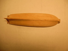
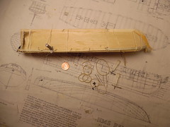
At the left is a clearer picture of the balsa MORRIS hull, where the bow has to be sanded down to the same configuration as on the plans of the PELICAN. Bulkhead additions were added to extend the stern the one inch to agree with the Hahn plan. Open spaces between the extended bulkhead additions were filled with Elmer's Carpenter's Wood Filler.

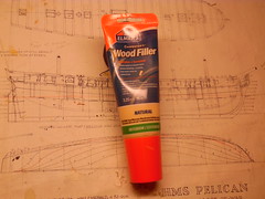
If I may put in a plug for Elmer's wood filler, that should be included in every wood modeler's box. Unlike most wood fillers that are packed in cans, this filler is contained in a plastic tube that is squeezed out like tooth paste, then the lid screwed back on. This has the advantage of having the filler remaining soft without contact to the air, unlike most canned fillers that soon dry out into a hard lump to be discarded.

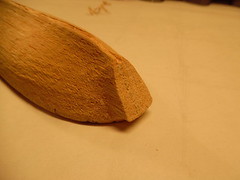
Trying to shape the balsa bow to agree with the Hahn plan required more planning. Consulting the plan drawings, the waterlines, which are horizontal stations drawn fore and aft, delinates the shape of the hull from the keel upward to the top of the bulwarks. On the Hahn plan, these waterline stations are marked "A" at the keel, then move upward to "F" at the waterline, where the ship meets its watery environment.

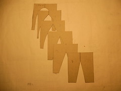
At each water line station at the bow, cardboard templates were cut out and labeled as seen at the left picture. Taking my Electro-File and inserting a sanding pad on the tip of the instrument, the bump on the balsa bow was gradually sanded down, while every so often, a bow cardboard template was inserted where a penciled "A" to "F" station was drawn to see that the sanding agreed with the template profile. After a slow sanding process, the balsa bow took the shape of the Hahn plan bow.

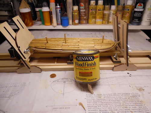
Now that the balsa bow and stern agree with the PELICAN plan, it's time to begin planking the hull with 1/4 inch wide planks cut from popsicle sticks on a hobby table saw. Before planking, the keel, the bow cutwater and the rudder stem was glued in place. Each horizontal plank was held in place with small elastic bands. Metal planking screws with an attached tab to hold the plank in place and also to prevent the plank from slipping sideways by the pull of the elastic bands. The copper penny gives the scale of the project.

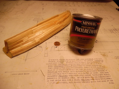
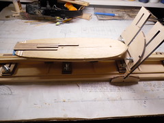
The hull planking is now completed and brush painted with Minwax Polyurethane, to seal the wood and fill tiny spaces. Painting the hull with acrylic paints will happen later.

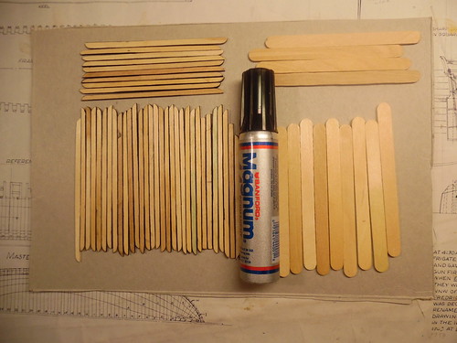
Before the deck planking began, each popsicle plank was rubbed with a black felt tip pen to sinulate the oakum and tar cauking that was used on the real 18th century ship to prevent water from leaking between the planks onto the inside deck.

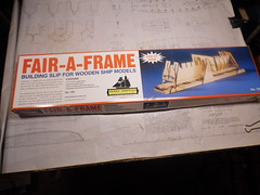
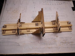
It's time now to plank the deck. To hold the model hull upright in a secure position, Model Shipways, Fair-A-Frame was used for this purpose. This device is used to build plank-on-bulkhead model ships, where the keel is secured in place by two horizontal clamps held in place by winged screws, while vertical supports prop up each bulkhead.

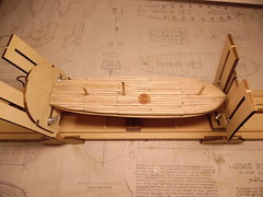
Here, the deck planking process has begun, while on the right panel, planking is completed. This panel also shows how the Fair-A-Frame holds the model hull secure. Wooden pegs were placed in holes where future masts were to be inserted. While decking planking, these wooden pegs made sure deck planking was accomplished around the mast holes, rather than over these holes.

The completed deck planking was stained with Minwax Golden Oak stain.

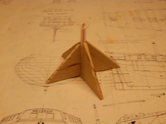
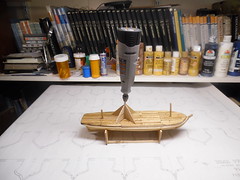
To make sure the mast holes were drilled absolutely true and straight in a vertical position for the future masts, a template was devised consisting of a plastic soda straw held in a upright position by wooden triangular supports. This template was placed over the mast holes and drilled deeper by my Dremel Cordless Electric Drill. The right panel is only for demonstration purposes. When actually drilling, both hull and template were held firmly in hand. Using a 90' right angle straight edge as a check, all three holes were found to be accurate.

I see by the clock, it's bed time. To be continued by copper simulation of the hull bottom.

     Happy modeling      Crackers    IndifferentBig Smile


Anthony V. Santos

  • Member since
    December 2012
Posted by rwiederrich on Wednesday, February 10, 2016 4:50 PM

Good to see you AVS...I build most of my vessels...utalizing parts from kits, but scratch building most of the vessel.  I will be looking forward to your build.

Welcome back.....I didn't know you...but hope too.Cool

Rob

JOIN OUR COMMUNITY!

Our community is FREE to join. To participate you must either login or register for an account.

SEARCH FORUMS
FREE NEWSLETTER
By signing up you may also receive reader surveys and occasional special offers. We do not sell, rent or trade our email lists. View our Privacy Policy.