SEARCH FINESCALE.COM

Enter keywords or a search phrase below:

Moebius Seaview 1:350 scale WIP

42504 views
928 replies
1 rating 2 rating 3 rating 4 rating 5 rating
  • Member since
    July 2014
  • From: Franklin Wi
Posted by Bakster on Thursday, May 25, 2017 8:52 AM

steve5

I'm enjoying this build steve , you seem to be having fun too mate .

steve


Hey Steve, thanks for saying and yes I am. It's a fun one for sure. I get to be a kid again in adult shoes. 

I found this cool image on the net. Below, and for your viewing pleasure...


  • Member since
    July 2013
Posted by steve5 on Thursday, May 25, 2017 1:11 AM

I'm enjoying this build steve , you seem to be having fun too mate .

steve


  • Member since
    July 2014
  • From: Franklin Wi
Posted by Bakster on Wednesday, May 24, 2017 9:51 PM

I decided to see if I could fabricate a better rendition of the I-beam junction.

Before:


After:


  • Member since
    July 2014
  • From: Franklin Wi
Posted by Bakster on Tuesday, May 23, 2017 8:53 PM

It is another rainy day here in Milwaukee. If it's not raining, it's cold. It has been a bad spring for our area, but it's been very good for my bench-time. 

Well, I have two I-beams done. These will go along the outer walls. I picked up some Evergreen I-beams to make them from. I bought the smallest they carried, #271. It is pretty dang close to the size I wanted.

The first thing that I did was to contour them to the curvature of the walls. I tried softening them up in hot water to warp them, but I had very minimal success doing it. What worked best for me was to position the piece over a lit tea candle. Through trial and error I found that 5 to 6 inches above the flame was the closest I could get without melting it. With constant motion and some pressure I was able to bend the beams relatively close to the shape that I wanted. The material has a memory to it, and so I had to settle with relatively close. The remaining curvature should easily tack down with glue.  

Once when I got the shape that I wanted, I scaled things down some by sanding the sides. After that, I drilled the holes. I am relatively happy with them. The spacing and such is not perfect, but close enough for my taste at this scale. 

Below: You can see what I am going after here. I will do some final fitting, add some paint, and then I can attach them.

The center I-beam that I plan to build will probably get attached to the window piece, and not this assembly.

That is all for now.


  • Member since
    July 2014
  • From: Franklin Wi
Posted by Bakster on Sunday, May 21, 2017 9:07 PM

Say CapnMac..you bring up some excellent points about the older technology lamps. That is all so true. The other aspect is heat dissipation. Incandescents can produce a fair amount of heat. So, there are heat considerations as well. To tell you the truth...all these issues would probably be more than I would want to deal with, and thank goodness for LEDs!

Thanks for that interesting reflection of a time that is not that long ago...


  • Member since
    November 2005
  • From: Formerly Bryan, now Arlington, Texas
Posted by CapnMac82 on Sunday, May 21, 2017 5:48 PM

Those inserts are really coming along.  I really jave to keep reminding myself that this is all 1/350.

In days of old (like the 80s, when LEDs were rare and exotic) it was a point of order that you had to provide access to "lit" kits so that you could replace lamps or batteries or the like.  So, you'd jump thorugh all kinds of hoops.  Like stashing a flashlight lamp attached to a turret or funnel to "drive" a set of fiberoptices.  That would be fitted to telescoping tubes with a tight fit to allow access.  Or using a metal tube for a tripod leg so that the metal could be used as a conductor and the neutral only having to be an insulated wire within (ain't physics fun? Smile)

Keeping potetially leaky batteries out of kits is also a good thing.  Not having to fish wires through stands is also a good thing.  So, I took to using one base for one electrical lead, and the other for its opposite. 

Simplicity is its own reward with things electrical.

  • Member since
    July 2014
  • From: Franklin Wi
Posted by Bakster on Sunday, May 21, 2017 1:10 PM

Well, as I thought through this more, I realized that I have to sort out the observation area before I can sort out the light.

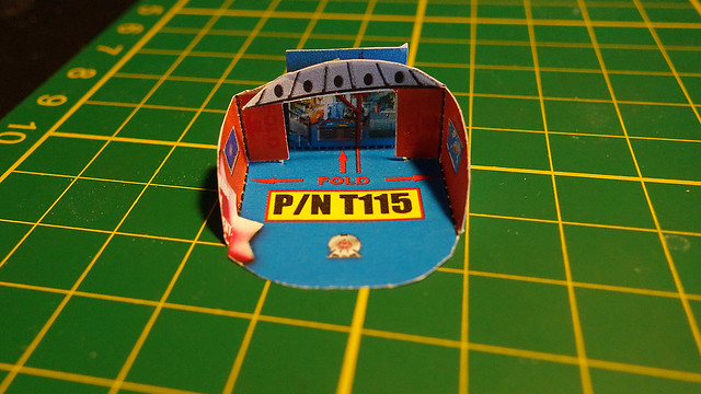
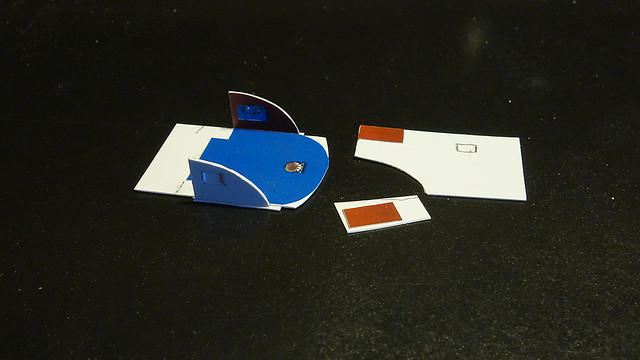
Below: Here is how the cabin dio folds together. As Emmet Brown said in the movie Back to the Future, "please excuse the crudity of this model."

This is loosely taped and this is not the actual piece. I first practiced on the instructions.

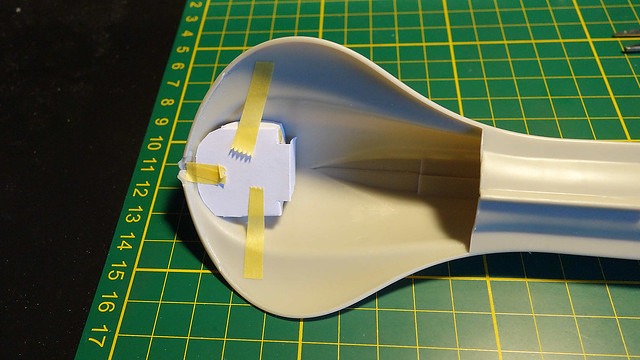
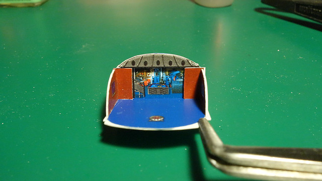
Below: Here is how it sits within the model.

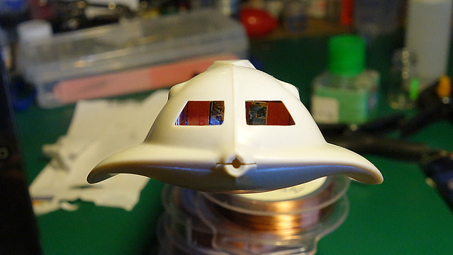
Below: Here is a rough gander at how it will look. Again, everything is loosely taped.

Being a guy that always looks to improve things, I tried to. I spent a good two hours cutting and fitting styrene sheets in an effort to get a better fit. In the end, I concluded that the designers of this foldout have it close enough.

So now what? I was not happy with the sloppiness of the paper. I know ... I will back each piece of paper with styrene. This should give me a tighter and more solid assembly. And that is what I set out to do.

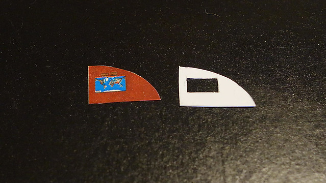
Below: I started with this side wall. As I was fitting this I noticed that light comes through the map. Apparently, this was by design. So, I cut a corresponding shape in the styrene backing so that the map will remain illuminated.

Below: As it is coming together.

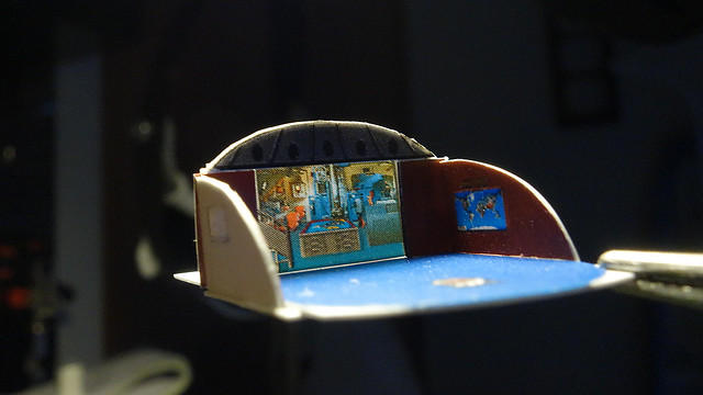
Below: It is complete. It still looks crude but I think that it's better than before.

Below: You can see how light shines through the graphics. It is too bad that the quality of the graphic isn't better, but I suppose at this scale, who will notice.

I have two more things that I want to try before I will call this assembly done. I will attempt to add some beams that will curve along the edge of the side pieces. I will also try to fabricate one that will travel back from the middle section of the window. Secondly, I might add a few chairs.

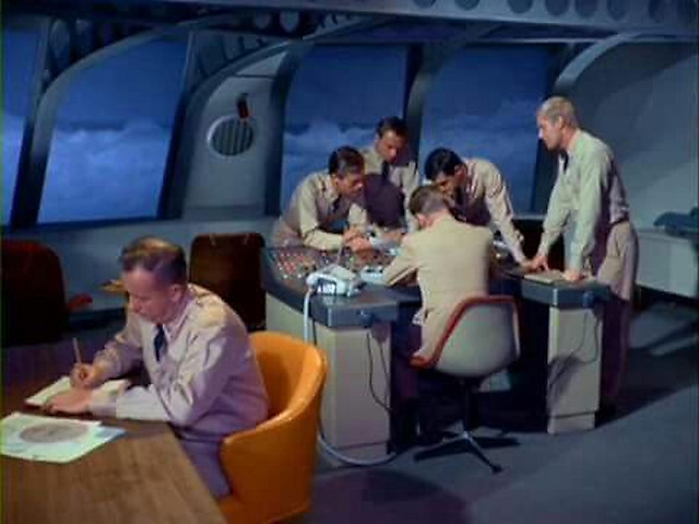
Below: Here is a screenshot of how the beams look. This image is from the movie version, the TV series is somewhat different. I am not too concerned about this. My goal is to get something that resembles a beam.

Below:


Captain!

Look!

There is a man peering into the observation windows!

Look out! He has a sanding stick!!!


  • Member since
    July 2014
  • From: Franklin Wi
Posted by Bakster on Sunday, May 21, 2017 12:12 PM

steve5

enjoyed that mate , love history .


Steve, I am glad you enjoyed it. I like history too. I hated it in school, but I love it now.

  • Member since
    July 2013
Posted by steve5 on Thursday, May 18, 2017 3:48 AM

enjoyed that mate , love history .


  • Member since
    July 2014
  • From: Franklin Wi
Posted by Bakster on Wednesday, May 17, 2017 9:16 PM

I found this article that has some interesting factoids on the development of the TV show.

http://www.vttbots.com/voyage_overview.html

  • Member since
    July 2014
  • From: Franklin Wi
Posted by Bakster on Tuesday, May 16, 2017 9:53 PM

I think that I am at a point where I need to sort out the subs interior lighting, and the construction of its base. The primary assemblies of the sub are done, as is the filler work. The exception to this is the main bottom plate at the bow. I need to leave this section open in order to work on the lighting, and to install the mock interior that I bought.

Its occurred to me that I will probably have to attach the PTs and the tail fin assembly much later, and probably after the sub is installed into its base. My concern is the irregular shapes of the sub and how it might hinder me in fitting the foam dio. For now, and until I figure things out, I had better leave those assemblies off. I will hold off painting the hull as well. I don't want to mess up a hopefully decent paint job by my repeated test fitting of the sub into its base.

Below: I ordered this battery pack housing today. What I like about this is that it incorporates an on/off switch in its design. This eliminates the need to mount a separate switch.

Where I will mount this is still up in the air. Worst case, I can fit it under the base in a recess. 2 AAAs is probably overkill for one LED, but AAA's are less expensive than coin cells, and it should certainly power the light much longer. 


I ordered these LED assemblies as well. It's a neat little deal. The assembly comes with sticky tape mounting, and the LEDs already have the required current limiting resistors.


https://www.hobbylinc.com/model-power-peel-n-stick-leds-3v-20ma-model-railroad-light-bulb-510-1


That is all for now.


  • Member since
    July 2014
  • From: Franklin Wi
Posted by Bakster on Monday, May 15, 2017 8:13 AM

GMorrison

The best putty I've ever used IMO is the Tamiya stuff, but it's pricey and not exactly something that can be picked up down at Ace.


That is interesting too. You know, I have a tube of Tamiya that I have not even cracked open. I became so dismayed with hobby putties that by the time I bought it, I said the heck with it. Go figure. My path is often a circular one. I will have to try that too.

  • Member since
    July 2014
  • From: Franklin Wi
Posted by Bakster on Monday, May 15, 2017 8:04 AM

GMorrison

Have you tried water instead of zipkick on CA? It pretty much has the same effect, without the fumes.


No, I have not. Wow...that would certainly change things. I will experiment with it. Btw, part of the toxic mess had made it onto my instruction sheet. I had to let it air out in the garage for a few days. Even now though, it still smells some. So when I am looking at it, it is not unusual where I will start to sneeze. Thanks for the tip G!

  • Member since
    September 2012
Posted by GMorrison on Sunday, May 14, 2017 11:46 PM

Have you tried water instead of zipkick on CA? It pretty much has the same effect, without the fumes.


 Modeling is an excuse to buy books.


  • Member since
    September 2012
Posted by GMorrison on Sunday, May 14, 2017 11:42 PM

I like Bondo. It comes in a fat toothpaste tube labeled as " glazing putty".

Never seems to go bad, easy to spread thin.

The best putty I've ever used IMO is the Tamiya stuff, but it's pricey and not exactly something that can be picked up down at Ace.

 Modeling is an excuse to buy books.


  • Member since
    July 2014
  • From: Franklin Wi
Posted by Bakster on Sunday, May 14, 2017 9:42 PM

Greg, thanks for your input as well. Yeah, I have yet to find the perfect putty. Some modelers swear by automotive putties. I have not tried that yet. 

Ok will do about the SV. Actually, I don't have much choice but to keep plugging away. Admiral Nelson is all over me about staying on track. He is a tough cookie. Tongue Tied

  • Member since
    May 2013
  • From: Indiana, USA
Posted by Greg on Sunday, May 14, 2017 7:04 PM

Thanks for your thoughts, Steve. You've confirmed what I figured, gotta move somewhat quickly, not sure that's for me. (My whole life is in slow-mo).

I've been using some Perfect Plastic Putty but have fallen a little bit out of love when I realized it cannot be wet sanded, which makes perfectly good sense and I should have seen that coming.

Keep on plugging away at hte Seaview. It's fun to watch.

  • Member since
    July 2014
  • From: Franklin Wi
Posted by Bakster on Sunday, May 14, 2017 4:56 PM

Greg
I've never experimented with filling with CA. I have heard you want to sand fast or it gets really difficult to sand, and also something about adding baking soda. Any comments?  

Greetings Greg--

Well, I have heard the same but I have never left CA on long enough to confirm it. I'd have to believe that it's true. Also, I have not tried the baking soda method. That is intriguing though.

I love using CA as filler. It's darn quick and dang durable. It has its limitations in certain circumstances but I go to it whenever I can.

Here is what I have learned, and what my preferences are:

1. I use the thick CA formula. I find it easier to control where the CA goes and it helps to eliminate low spots.

2. I apply a spot of CA to a piece of cardboard and draw from there. I use a needle to apply it to the model.

3. I try not to do too much, too fast. I will process a small section and then move on to do more.

4. I use accelerator to speed up the potting time. As mentioned earlier it helps to take the guesswork out of when it's ok to sand. Plus, if I don't have to wait, why wait.

5. This is KEY... I start sanding with an aggressive grit. You need to rip the material down as fast as possible. I will sand with this grit until the glue appears flush. Good lighting and magnification is important.

6. I switch to an intermediate grit and smooth it more.

7. I end with a fine grit to get a glass like finish.

Most often I will have to repeat this process another time because invariably I find a few low spots. But, you only have to fix those low spots.

Below: I can't tell you what the grits are with the first two sanding sticks, but the image gives you an idea of what they look like. You can gauge from there. The cloth is 2400 grit.

  • Member since
    May 2013
  • From: Indiana, USA
Posted by Greg on Sunday, May 14, 2017 12:42 PM

Neat idea on the little dropper bottles. You are lucky to have an AS&S store nearby. I'd likely be like a kid in a candy store in there.

I agree the forward stabilizers look goofy, I like it better with them gone.

I've never experimented with filling with CA. I have heard you want to sand fast or it gets really difficult to sand, and also something about adding baking soda. Any comments?


  • Member since
    July 2014
  • From: Franklin Wi
Posted by Bakster on Sunday, May 14, 2017 12:20 PM

After completing one of the PTs last night, I felt like working on something different.

Below: There is one thing that has been nagging at me about this model, and that is the forward stabilizers. In my opinion, the recessed panel lines are massively exaggerated making the sub look toyish. To confirm my thinking I found some screenshots from the show. In every case I could not even see them. That is not to say that they were not there on the studio prop. I did find an artist's rendition that had them, but the scale of the panel line is barely visible. So, armed with that, I set out to remove them entirely.


Below: CA magic is applied.


Speaking of CA, I am happy to report that my CA accelerator bottle is working excellent. I accidently knocked it over twice with no spills. Also, the amount of control that I gain by using this makes me feel like a surgeon. If anyone is interested, you can purchase them through the link below. Unfortunately, for on-line purchases, the min buy is 10. I am blessed to have a store nearby and I can buy as few as one. If anyone is interested, I can pop one in an envelope and then mail it to you. I figure $1.50 should cover my costs. PM me if interested.

https://www.sciplus.com/s/4?sStr=Bottle


Below: I should have imaged this piece/fit showing what it looked like before I had worked on it. Needless to say, it needs work. I have more work to do but the majority of it will come later when I am ready to close it up. At that point, I will fill the gaps with CA and smooth things out.

All this work that I am doing is kind of a moot point because the sea sculpt will cover it. But, I'll know it's there, and it gives me a chance to practice my filling.


Below: Buyer beware. I found this aftermarket decal sheet and I decided to order it. I was hoping to use it for the ballast vents, and if I was lucky, maybe the missile hatches. Well, the quality of this thing is horrid. You be the judge. There is one other thing about this. The entire graphic is one decal. So that means, you'd have to trim everything out too. This is being returned.


  • Member since
    July 2014
  • From: Franklin Wi
Posted by Bakster on Saturday, May 13, 2017 10:18 AM

Well, the assembly went fine, but with one gripe. The biggest gripe that I have is that the baffles are amazingly undersized for the assembly. The end result is some major gaps between the baffle and the wall of the propulsion tubes. The good news is that you can't see the gaps by looking.

The way to tackle this assembly is to position the baffle as best as you can, and then tack them in place with some CA. Moving outward then... I glued the diving plane into position. Lastly, you align the hole on the rudder to the pin on the PT housing, and then do the same on the other side using the other PT section. I did not glue these joins because they are tight enough on their own. Doing so leaves you with the ability to pivot the rudders after install. That is kind of cool. I should note that I installed the props to the baffles prior to all of this.

Lastly--I can see why that as a kid I had problems with this assembly. Building it this time around I have the benefit of an almost instant bond that CA provides. This really helped me with the assembly because with the loose fitting baffles and diving planes, they need to be secured really well before advancing to the next steps. Given my age at that time, and the natural impatience of being a kid, it was beyond me to wait the long hours of curing that tube glue requires. 

What's next? I need to fill the gaps on the PTs.

  • Member since
    July 2014
  • From: Franklin Wi
Posted by Bakster on Wednesday, May 10, 2017 9:47 PM

I mixed a darker shade of gray for the propulsion tube outlets. I thought it would be nice to add a little contrast to the assembly/model. After all, most of the model will be in one shade of gray. The instructions said to paint the props in brass; I went with it. The rest of it is in line with the instructions.

My recollection as a kid was that I had a terrible time assembling these. I seem to recall a fit issue with the baffles, and then there is a bit of a balancing act with the diving plane and rudder. I was pretty young then so maybe it was just me. We'll see how this goes. 

Building this kit is bringing back a lot of lost memories. I am still enjoying this very simple build. It's a fun one.


  • Member since
    July 2014
  • From: Franklin Wi
Posted by Bakster on Tuesday, May 9, 2017 10:30 PM

A learning moment...

During my 4 hour filler marathon I had an oops that set me on a new path. I use a CA accelerator as part of my CA filler process, and the reason that I do is because it speeds the process up, and it takes the guesswork out of when I can start sanding. I can begin sanding as soon as I hit the CA with the accelerator. Anyway, the bottle that I have is a decent size and it is designed so that you spray the area being worked on. The problem with this is that it sprays in too large an area, and in too heavy a volume. It's a waste of the product and a nuisance for cleanup. So, what I do is remove the spray head and use the siphon tube to drain some of the accelerator over the area that I am working on. This works pretty well, at least up until I knocked the bottle over. It was the sound of clug clug clug all over my work station. Do you know how Homer Simpson shrieks when he does something stupid? Well, that was me when this happened.

It is said that necessity is the mother of invention. I say, gosh darn right. I went to a surplus store and found this small applicator bottle. The benefit of using this bottle is twofold. The first is that it makes it pretty much spill proof. Secondly, the design allows me to apply the accelerator one drop at a time, and precisely where I want it. Why am I telling you all this? Eh, maybe it will help someone, and at the same time it is fun to share the stupid things that I do.


Back to the build...

I am currently working on the propulsion tube assemblies. The components are de-sprued, sanded, washed, and just tonight painted. I will install them into the outer housings once the paint thoroughly dries. Then I will fill the joins and set the assemblies aside for final paint.

Below: the assembly as shown in the instructions.

Lastly, I am still researching the lighting and the base to build the sea-sculpt in. I have been looking at some shadow boxes as a possible platform to build the water on/in. I kind of like the idea of having the water enclosed in a frame and filled to the top.

More to come.

  • Member since
    July 2014
  • From: Franklin Wi
Posted by Bakster on Sunday, May 7, 2017 4:22 PM

Greg
Those darned simple-looking kits, eh?!

Yeah buddy... this ain't no Tamiya kit! On these older kits a person spends most of their time just trying to bring it up to snuff. It is sad, but true. I'm good with that though. It gives me an opportunity to practice my puttying. Stick out tongue

PS: It might have been faster if I used something other than CA. That is a big might.   


  • Member since
    July 2014
  • From: Franklin Wi
Posted by Bakster on Sunday, May 7, 2017 4:08 PM

GMorrison

Looking sharp. It would also be a good time to figure out how to mount it to a base. 

For instance you might glue nuts in along the keel for screws.


Thanks, and that is a good thought. What I had been thinking is to use parts of the stand that comes with the model. The keel already has holes molded into it for the stand. So, I could use the two coral looking pieces shown below, and cut them to the height that I need. Then maybe, hot glue the bottoms to the base. If I have a lot of room I could even incorporate the bigger piece for more stability. If you see anything that I may be missing, let me know.

Thanks again!


  • Member since
    May 2013
  • From: Indiana, USA
Posted by Greg on Sunday, May 7, 2017 12:25 PM

Coming along good, Steve. Those darned simple-looking kits, eh?!

All fills and stuff look good. The main seam between the missile tube covers looks challenging indeed. I don't know if I have 4 hours worth of patience for sanding so Bravo to you.

  • Member since
    September 2012
Posted by GMorrison on Sunday, May 7, 2017 10:52 AM

Looking sharp. It would also be a good time to figure out how to mount it to a base. 

For instance you might glue nuts in along the keel for screws.

 Modeling is an excuse to buy books.


  • Member since
    July 2014
  • From: Franklin Wi
Posted by Bakster on Sunday, May 7, 2017 10:31 AM

Here is 4+ hours work of filling and sanding bliss. This was painstaking because there is not a lot of room to work with having those hatches so close to the join. I did not want to mess up those missile hatches.

I used CA to fill the gaps. CA dries relatively clear, so it is hard to gauge from the photo what has been done. Because of that, it looks like there are still some gaping gaps. Heck, even to the human eye it is hard to see. I had to position the lighting to see how it reflects, and I also used my fingernail to feel for ridges. I won't really know how well this turns out until I hit it with some primer. I think that I have it pretty close though.

I fixed a defect at this location as well. There was a hole from where the plastic didn't fully make it through the mold. I used CA to fill, build up, and shape it to what it should likely be.

What is next? I don't know yet but I think part of the day I will start researching the interior lighting. I am quickly approaching the paint stage, and I will need to get the lighting sorted out. 

  • Member since
    July 2014
  • From: Franklin Wi
Posted by Bakster on Friday, May 5, 2017 10:38 PM

Here is something that started out well. Both halves of the sail assembly came together very nicely, and I thought that I was heading for a slam dunk. But, not so fast. When it came time to install the top piece it became apparent that I had a fit issue to deal with. The image shows the problem. There is more though. The top piece was too wide as well.

So, this was going to require some shaping, which I did. I took it a step further by filling in that join with CA. I searched the internet for Seaview images and all the images that I could find appear to show the sail as one piece. In other words, there is no top piece creating a join. I was glad about this because the filler helped me bring the assembly to the shape that I was looking for. I was struggling to get there without it.

Aside from this, I worked on filling the gaps on the keel. Tomorrow, I will work on filling the joins on the top deck.


  • Member since
    July 2014
  • From: Franklin Wi
Posted by Bakster on Thursday, May 4, 2017 10:05 AM

Greg


Surely glad to hear that. They say this hobby is supposed to be fun, you know. That's what I hear, anyway.


Yeah that is what they say. Smile


JOIN OUR COMMUNITY!

Our community is FREE to join. To participate you must either login or register for an account.

SEARCH FORUMS
FREE NEWSLETTER
By signing up you may also receive reader surveys and occasional special offers. We do not sell, rent or trade our email lists. View our Privacy Policy.