SEARCH FINESCALE.COM

Enter keywords or a search phrase below:

Carving an 18th century ship's launch at 1/8th scale.

3600 views
9 replies
1 rating 2 rating 3 rating 4 rating 5 rating
  • Member since
    December 2006
  • From: Jerome, Idaho, U.S.A.
Carving an 18th century ship's launch at 1/8th scale.
Posted by crackers on Saturday, October 21, 2017 2:39 AM

                                       INTRODUCTION

Since ancient times, larger ships often carried one or more small boats as auxilary craft. These boats were towed behind the mother ship. Later, this auxilary craft was stowed on the main deck. By the 18th century, the ship's launch was the main auxilary boat stowed over the main hatch with other lesser boats such as a pinnace, a cutter and a smaller dinghy nested on top. On larger man-of wars, all boats were rested on skids side-by-side on the main deck. The purpose of the launch was not onlty to transport officers from ship to ship, but also to shore. The launch also served as a transport for supplies, or carry multipal personnel to unload on beaches. On sailing ship kits, of either wood or plastic, auxilary craft are included in the kit. For scratch builders, making a launch is a necessity if authenticity is to be required.


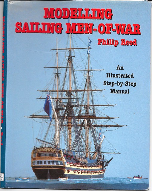
The inspiration for the lanch carving project came from the book,"Modeling Sailing Men-of War", by the expert modeler, Philip Reed. This publication is a step-by-step guide for the construction of the 74 gun line of battle ship, HMS MAJESTIC. All steps of construction is enployed by a series of photographs with accompanying written texts of instruction. Based on the design of HMS CANADA, by William Batley, MAJESTIC was commissioned in 1790 and served in most of the major sea battle duing the Napoleonic conflicts of the late 18th century and early 19th century wars with France. Reduced to a 32 gun frigate in 1812, MAJECTIC helped capture the USS PRESIDENT in 1815. After 26 years of service, MAJESTIC was broken up in 1816.

On page 83 of "Modeling Sailing Men-of-War", the author begins a series of photo-texts on how to construct a ship's launch by making molds of the launch with ABS plastic. Rather than follow this route, I"ve decided to carve a launch from scrap pine by using a Dremel 7300 battery powered cordless drill with a table saw, gauging berrs on the drill and final sanding with an Electro-File hand sander. Returning back to the book to complete the fitting out of the model launch.

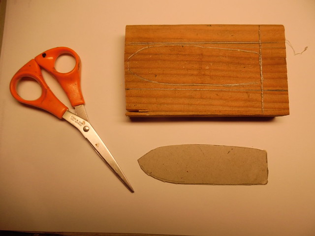
The first step of launch carving was the selection of a piece of scrap pine. With an architectural scale ruler, 1/8th scale was decided for a 34 foot launch for a French frigate that has been put on the back burner for later work. A cardboard template of the launch profile was cut with scissors and traced on the scrap wood. Parallel pencil lines were drawn on the scrap wood to indicate the first cut on a table saw. The stern part was also penciled in.

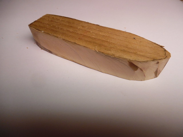
This is the rough cut of the model launch after the table saw removed the outer scrap pieces.

Sanding for a rough outline of the launch. The parellel lines on the top of the launch-to-be is where a grove is to be cut to receive the keel.

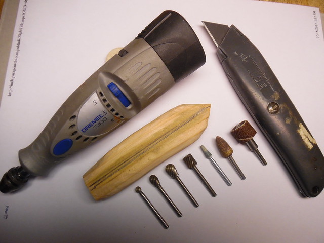
Here are the essential tools to begin shaping the launch. The box cutter knife was used to shape the general outline of the launch. Then, the Dremel battery powered cordless drill began to hollow out the interier of the launch and the outer profile. The bigger burrs employed on the drill for rough gouging, while the smaller burrs for closer detail. Sanding heads when required.

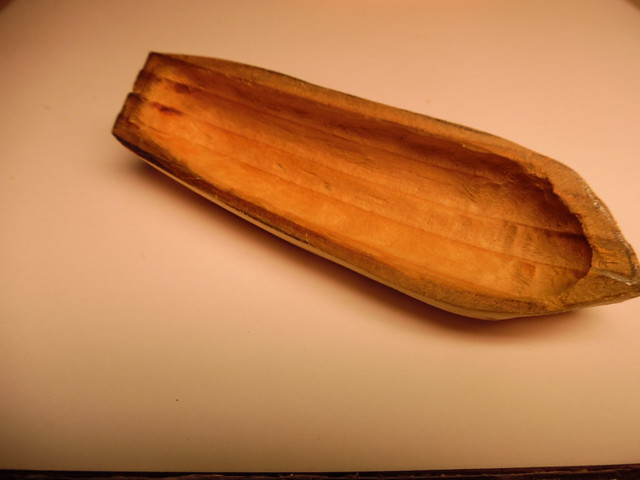
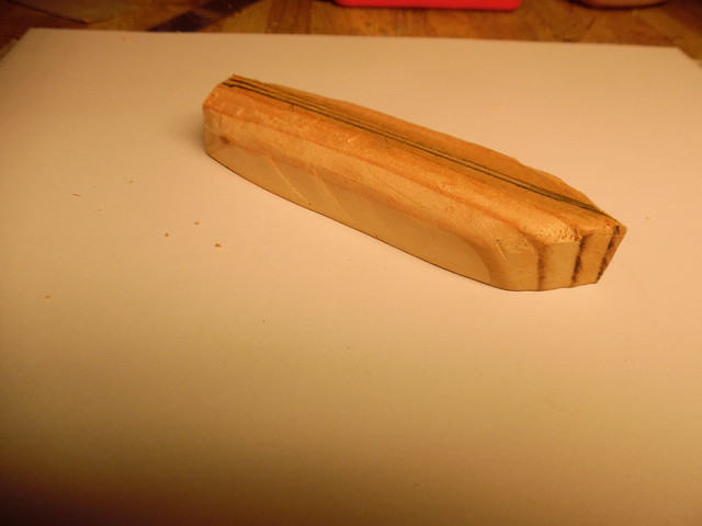
Finally, the launch is in the first stage of creation after much hollowing out the enterior of the project.

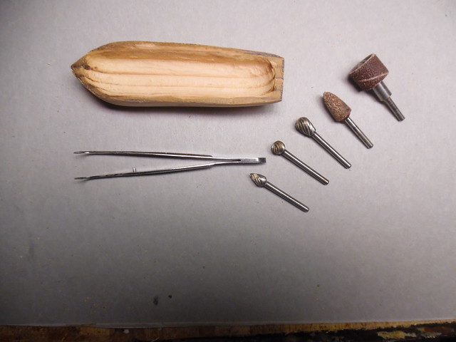
Here is the progress so far by gauging and sanding. At this point, caution is required in this shaping process so that the walls of the launch is not over cut and ruined. To insure that gauging and sanding did not go to far, the launch was held close to a naked illuminated light bulb. If light shown through the wood, then it was time to stop gauging and sanding. The tweezers give an example of size and scale of the launch project.

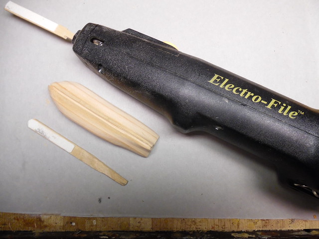
Final sanding begins. The Electro-File sander does the job quite well, to eliminate the repetative motion of sanding by hand. The small sanding stick is for hard to reach places where the Electro-Fil can not reach. This tool has an oscillating motion to sand a sanding stick that has sand paper attached. The oscillating movement is much like a turkey carver that is used to cut slices of the Thanksgiving bird. A grove has been cut on the underside of the launch to receive the future keel.

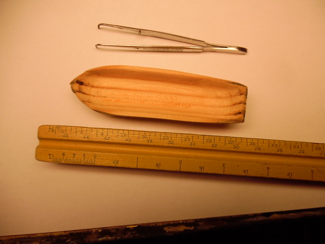
Here is the finished product after sanding with the Electro-File beside an architectural ruler, which shows a 34 foot launch at 1/8th scale. The next process will be the application of thin width computer paper strips on the outside of the hull to simulate clinker planking from the keel to the gunwale.

To be continued     Happy modeling      Crackers    SleepYeah


Anthony V. Santos

  • Member since
    November 2005
  • From: Formerly Bryan, now Arlington, Texas
Posted by CapnMac82 on Saturday, October 21, 2017 11:17 AM

Oh, you mean 1/8" = 1'-0" scale.

That's 1/96 scale.

I was boggling a bit at what "carving" would be needed at 1 1/2" = 1'-0"--1/8 scale.

A 40' ship's launch would be 60" long at 1/8 scale.  Rather different than the 5" at 1/96.

Ewart Freeson in Model Open Boats, describes a technique similar to the above.  The nain different is that the master block is split at the keel line to give more access while shaping the hull form.  The two halves thus created are mated to a profile of the keel for final finish.

  • Member since
    February 2016
  • From: Western No. Carolina
Posted by gene1 on Sunday, October 22, 2017 9:18 AM

I was wondering the same thingCapn, Mac. I worked in what I always called 1/8" scale & 1/4" scale when drawing house plans, so I sort of knew what he was talking about. My finished plans were always 1/4" = 1' 0", & sketches were 1/8".  

   My yellow racer picture is a hand carved 1911 Indy Winner the Marmon Wasp.I got the plans at Indy & hand carved it from Bass wood with plastic & metal details & O ring tires. Bass wood is much easier to carve, without all the grain.

  I do like what you are doing with the ships boat. I think a boat is harder to carve than an old race car with straight lines. 

  • Member since
    November 2005
  • From: Formerly Bryan, now Arlington, Texas
Posted by CapnMac82 on Sunday, October 22, 2017 8:59 PM

I sued to think in terms of which edge of the scale I was using, but, once AutoCAD took over the industry, that faded away.
Spend 20-something years modeling things at 1:1 and only setting them to scale in Paperspace also have an effect. 
Side effct of that is that I more think of things in their display scale, e.g., 1/96 or the like rather than "eightn." per se.

Vive l'difference.

  • Member since
    December 2006
  • From: Jerome, Idaho, U.S.A.
Posted by crackers on Sunday, October 22, 2017 10:45 PM

Thanks CapnMac82. I based my scale on my architectural ruler which I believed to be correct. That scale seemed to be the accurate for a model of a French frigate that has been put aside while other project are works in progress.

Happy modeling    Crackers

Anthony V. Santos

  • Member since
    September 2012
Posted by GMorrison on Sunday, October 22, 2017 11:59 PM

Architectural scale.

Def: why architects drink too much.

I had the great benefit of being educated in part, and working in countries with metric systems.

I'm currently building a ship model on 1/144 scale. 1" = 12'-0".

Go figure.

 Modeling is an excuse to buy books.


  • Member since
    December 2006
  • From: Jerome, Idaho, U.S.A.
Posted by crackers on Monday, October 23, 2017 12:11 AM

The keel ,cutwater and stern stem have been added to the finished carved launch. Next, the simulated clinker planking will be added to the outside hull.

First, the defination of what clinker planking is on a boat hull. Carvel planking is the most common form of outside boat planking. The planks are fixed to the boat ribs with the plank edges butted against its neighbor. Clinker built (also known as lapstrake) hull is where each plank edge is overlaped with its bottom neighbor and fastened to this bottom plank starting from the keel to the gunwhale. The main advantage of clinker over carvel is that clinker build gives a stronger hull. First developed in Northern Europe by the Vikings on their long ships, this type of planking is usually preferred on launches because of the heavy duties the launches often performed. The launches had to be stronger built because of their varied tasks.

To simulate a clinker built hull on the model launch, thin computer paper 1/8' in width were cut with a hobby knife along the edge of a metal ruler. The strips were trimmed with a scissors and glued with wood glue to the launch hull. The starboard side is completed, while the port side is yet to be added.

Happy modeling    Crackers   SmileWow

Anthony V. Santos

  • Member since
    December 2006
  • From: Jerome, Idaho, U.S.A.
Posted by crackers on Sunday, November 19, 2017 6:07 PM

After the clinker strips of the outside hull was completed and painted by acrylic white, the launch was turned over to prepare for the positioning of the ribs. Thin wood sections were first attempted, but after repeated failures, cardboard was then cut out and used, avoiding the frustration of splitting and breaking when fitted to the interion of the hull. After this task was finished, the insuide of the hull was painter with ocher yellow.

A thin stip of wood was positioned for the eventual placement of the seats ( thwarts). From cardboard strips, the gunwales were cut out, painted the outboard blue and the inboard red and held in place with paper clips and small wooden clothes pins.

After the clips were removed and minor touchups with the blue and red paint, the end result was ready for the next addition to the hull.

The next addition will be gratings on the bow and stern, plus floor boards on the bottom of the launch to keep the feet of the rowers dry should there be bilge water on the inside the launch.  To be continued.

Happy modeling.     Crackers     Huh?


Anthony V. Santos

  • Member since
    December 2006
  • From: Jerome, Idaho, U.S.A.
Posted by crackers on Sunday, December 3, 2017 6:17 PM

The floor boards and grating is added to the bottom of the launch. The purpose is to keep passenger and boat crew feet dry should there be bilge water accumulation in the bottom of the launch. The grating is made from my wife's plastic canvas grid material, which is perfect for this requirement. A piece of this plastic is seen at the left of the launch model.

For those who are unfamiliar with the plastic canvas hobby, it is craft material of lightweight plastic with spaced holes in a grid pattern used as a foundation for needle point embroidery with knitting wool string. A finished example of plastic canvas work, is a rowboat my wife made with photo pictures of our pets.

The rowing seats have been added with a forward location for a boat crew member to manage and tie up the launch on a side of a ship, or pier. The after cockpit is for the seating of any important individuals.

To be contunued  Happy modeling    Crackers    Smile

Anthony V. Santos

  • Member since
    December 2006
  • From: Jerome, Idaho, U.S.A.
Posted by crackers on Friday, January 12, 2018 6:02 PM

After the rowlocks for the launch were applied to the little launch model, it was time to add some oars by creating the blades and the shafts for these oars.

The shafts for the oars were made by using a steel drawplate to pull 1\8th wood dowels down to 5/64th inch in diameter, then attaching eight blads to eight shafts after the shafts had been cut to size.

Here are all the oars aliened to the completed launch. These oars are not glued in place, but just positioned for the picture.

The completed oars are now glued in place as positioned when stowed inside the launch. The cradle that will be placed on the bottom of the launch to hold the launch in place inside the frigate well, is seen beside the launch in this picture.

Here is the launch on top of a larger pinnace of my incompleted scratch built model of the French frigate LA RENOMMEE, later HMS RENOWN, after her capture by the English in 1757.

This NOT my completed scratch built model of the LA RENOMMEE, but rather a picture I copied off the internet. If this were to be my completed model, this is how the pinnace and launch would be stowed inside the frigate well. Unfortunately, I became bored and turned to other projects. In the near future, I will continue to complete the LA RENOMMEE model.

LA RENOMMEE was a 30 gun frigate built at Brest, France in 1744. Captured by the Royal Navy while on patrol on the Caribbean Sea, on September 27, 1747. Taken to England the ex-RENOMMEE, then renamed RENOWN, was extensively surveyed and found to be a fast sailor under the right wind conditions. Her under hull contour was copied as a prototype for future English frigates. After serving for almost 25 years in the Royal Navy, HMS RENOWN was broken up at Woolwich in May 1771.

This completes my thread for making a launch, a necessary addition to any 17th and 18th century warship model.

Happy modeling      Crackers   Smile

Anthony V. Santos

JOIN OUR COMMUNITY!

Our community is FREE to join. To participate you must either login or register for an account.

SEARCH FORUMS
FREE NEWSLETTER
By signing up you may also receive reader surveys and occasional special offers. We do not sell, rent or trade our email lists. View our Privacy Policy.