SEARCH FINESCALE.COM

Enter keywords or a search phrase below:

1:72 Iowa Class Mark-7, 16"-50cal Turret #1 with Custom Interior Start-to-Finish

30211 views
270 replies
1 rating 2 rating 3 rating 4 rating 5 rating
  • Member since
    January 2015
Posted by TheMongoose on Saturday, December 17, 2022 11:14 PM

Awesome stuff! If I don't see it in Luisville I'll have to get to the museum to see it in person.

In the pattern: Scale Shipyard's 1/48 Balao Class Sub! leaning out the list...NOT! Ha, added to it again - Viper MkVii, 1/32 THUD & F-15J plus a weekend madness build!

  • Member since
    October 2019
  • From: New Braunfels, Texas
Posted by Tanker-Builder on Sunday, December 18, 2022 7:24 AM

I have Been Amazed!

          It(this project) keeps me thnking about the Buildout that the Skipper(Keith Mullin) and I did for the U.S.S.Wisconsin. Near 17 feet of Battleship model for the Nauticus Museum. Arrived in good shape and thankfully NOT needing any repairs from the trip.

          In your case I would pad the daylights out of it. I have been known to go to places like Jo-Annes to get Silk and Crepe cloth to  help cushion a model. They work well. It is still a Supercalifragilistic Job!!!

  • Member since
    March 2012
  • From: Louisville, KY
Posted by Builder 2010 on Monday, December 19, 2022 6:43 PM

Things are moving fast and furious. I was working on a couple of fronts today all progressing forward.

Areas of attention were: the central column, bloomers, power switch for base.

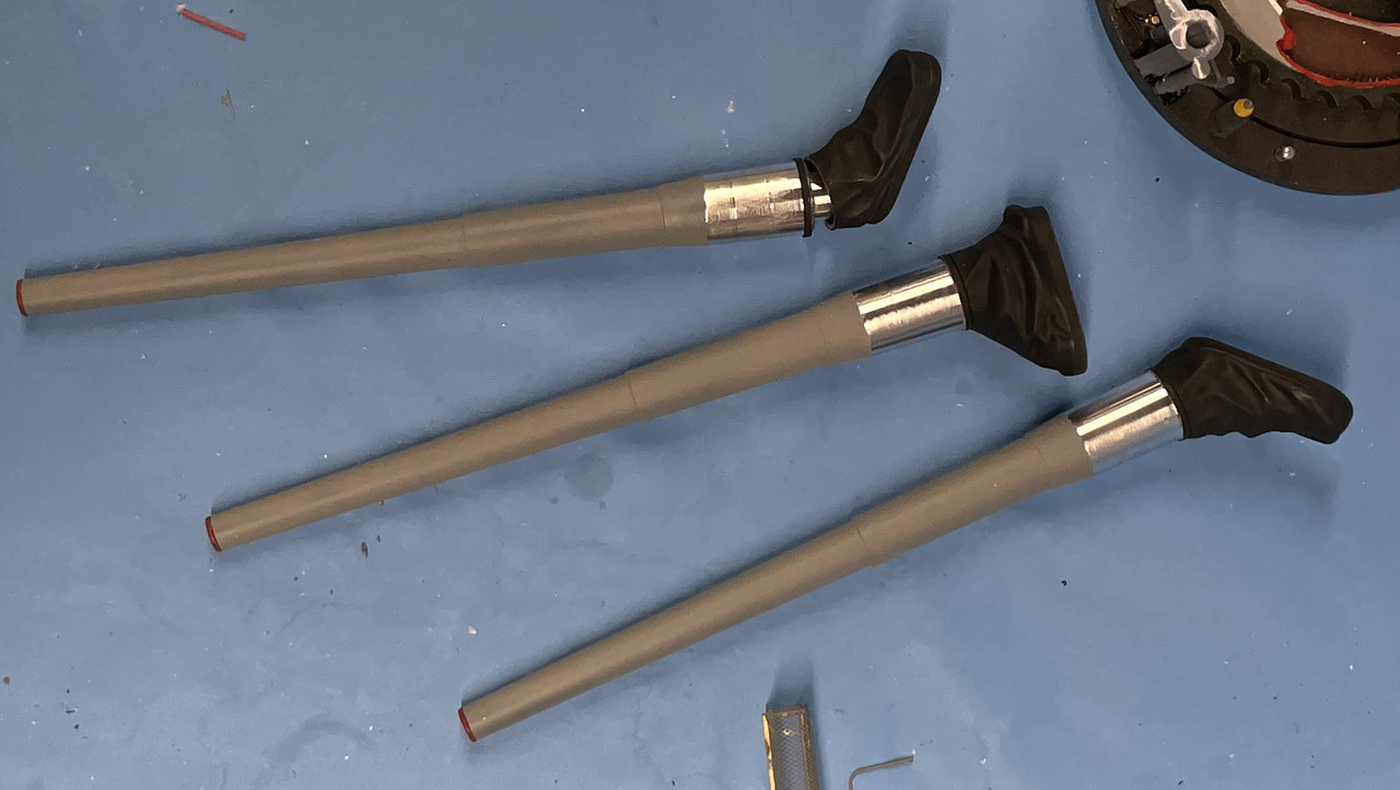
I did the bloomers first with a mix of Tamiya Rubber Black and NATO Black. I used 3M blue tape to mask the little flange at the rear of the slide area and the tape pulled paint of the barrel. I resprayed and fixed it. I wondered why the airbrush was gumming up so badly. I inadvertently used IPA to thin the Life Color paint. Like Vallejo, these acrylics not only don't thin with alcohol, they form rubbery blobs that clog airbrushes. I realized my error, cleaned up the mess and then thinned it with AK universal acrylic thinner. Bloomers are not glued here. I will glue them to the turret first, then install the guns.

A critical step was figuring out how long the central column needed to be. The column I was using up to this point was just a guesstimate that didn't take into account the actual combined depth of the wooden base AND the 3D printed mounting flange. I measured that combined distance, assembled the stack with another, overly long, column and marked this depth.

Here's a closer look at that mark.

I took this piece and cut it off at the mark on the chop saw.

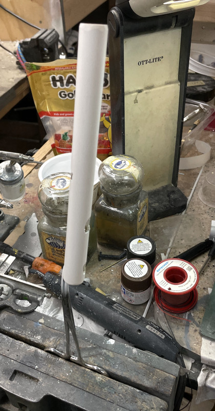
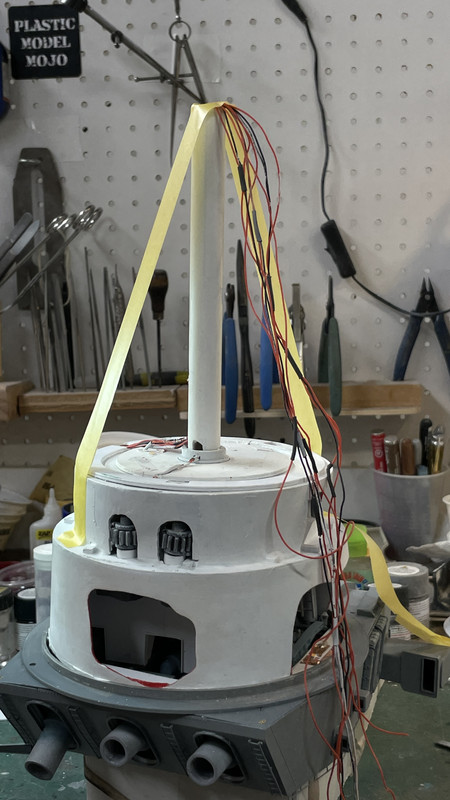
I then had to cut the various access points in the column for the wiring harnesses to go under the base. I just went at it with the carbide router. They didn't to be pretty since they're out of sight (for the most part). I then clamped on a forceps and sprayed it flat white. I almost blew it by starting to run wires before painting. I caught myself after just doing one wire set. I had to keep my wits about me when figuring where the access ports were going to go. They had to align with the general direction that the wiring was approaching the column.

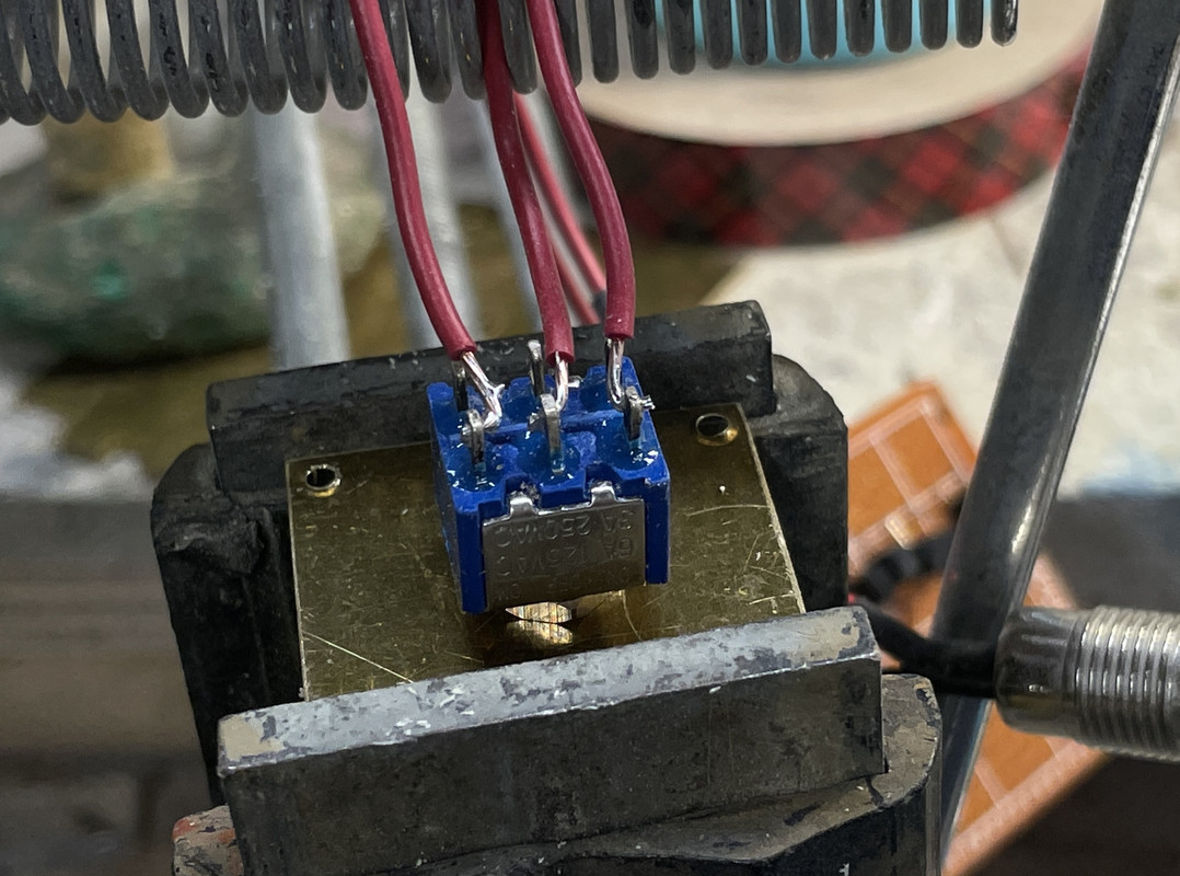
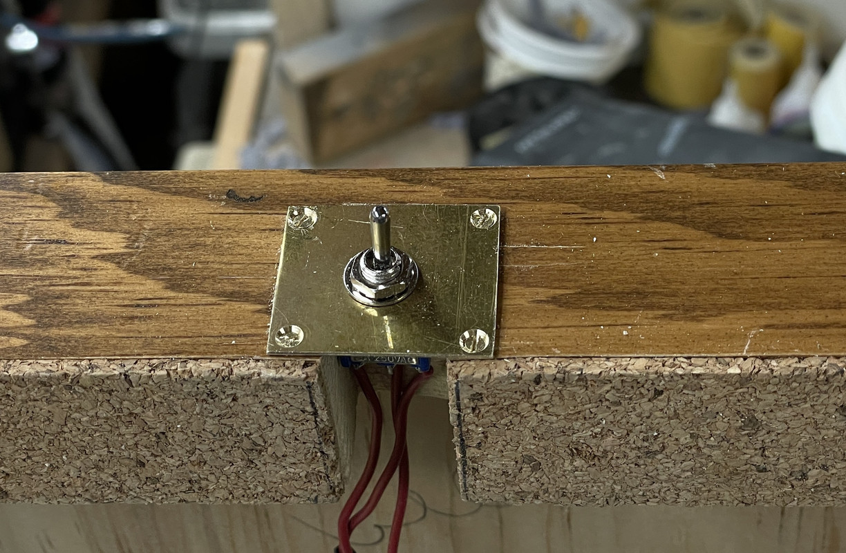
While this was drying I got to work installing the missing power switch in the wooden base. While I felt bad about hacking into the beautiful piece of woodwork crafted by my friend Bryant Mitchell, it was necessary. I have a few left over double pole/double throw toggle switches from building my model railroad. I only need one pole, and one throw for that matter, but I can use both throws by making the output come from both sides. So middle is off and switching in either direction is on. 

I consider myself a pretty good solderer, but after taking this image, the outer two leads just fell off. The switches are German and I got them when first building the railroad when on assignment at Henkel in Düsseldorf, Germany. That was 1999, which makes this switch 23 years old and the terminals had oxidized. I went at them with a file and resoldered the wires correctly.

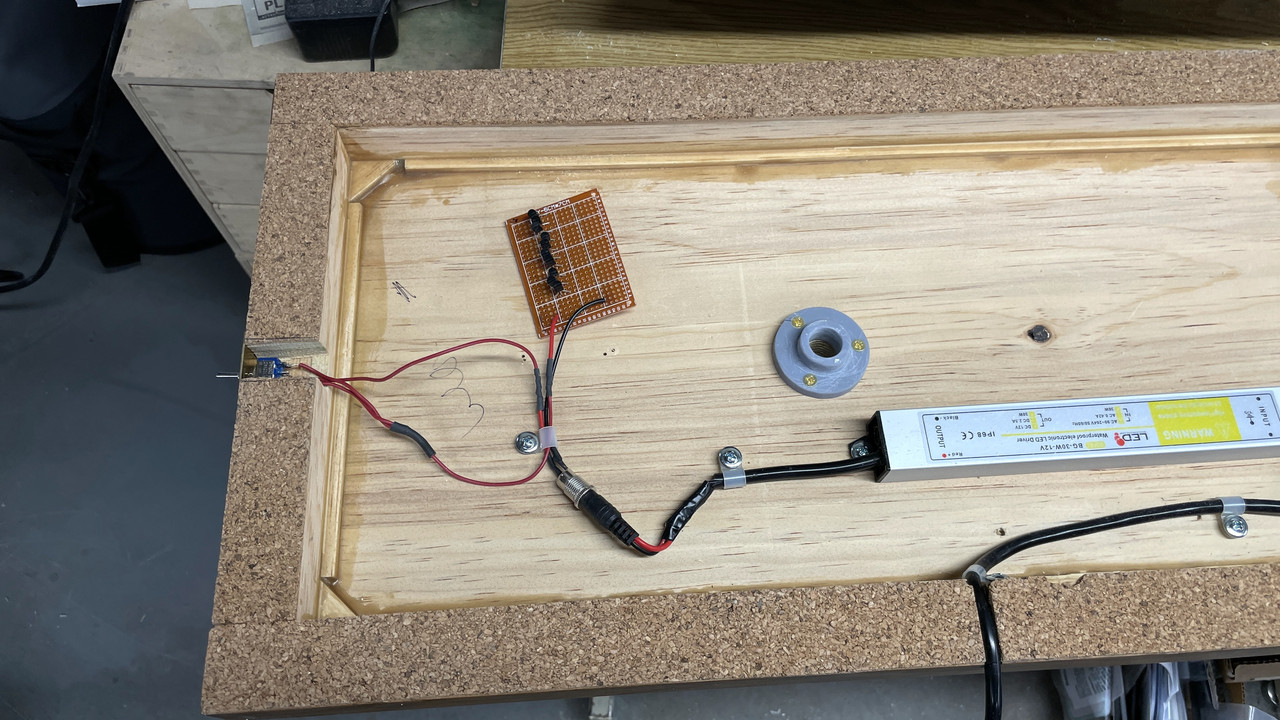
Here's the wiring completed as of now. The circuit board is just floating there since I have to terminate a whole lot of LED leads on its underside.

And here's the exterior.

By the time I got done this sub-project, the column was dry and the wiring could begin in earnest. I first fished the twin lead from the bottom of the electric deck (lights the first projectile flat) which goes directly from the top to the bottom.

Some of my wires were short. I was estimating the length during the LED wiring phase, but shortchanged myself. I had to extend some about 6" just to have enough slack to do all the terminating without straining anything. I used a piece of heavy gauge solid-core wire to fish the bundle through the access hole and out the bottom.

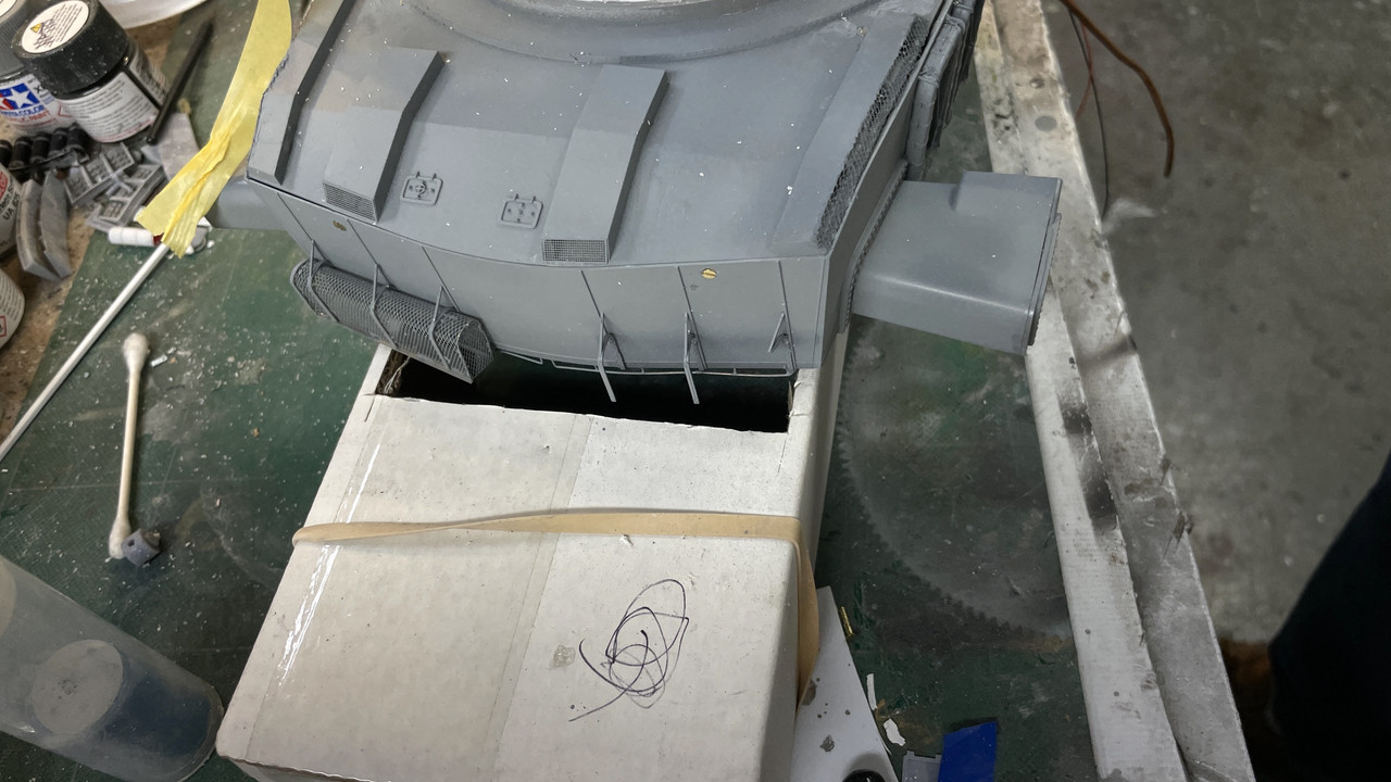
Here's the entire mass now fed through the frst access hole. There are two more sets that need to go in. I made a large notch in the e-decks outer flange so the wiring wouldn't affect the deck nesting. I overcoated it with Bondic to secure them before fishing. I may have to cut one more access hole for the two-wire leads from the 2nd Projectile deck.

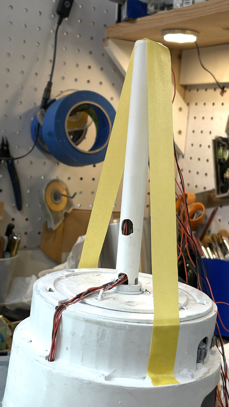
With the harness in, it was time for another milestone; the gluing in of the column's top into the boss under the electric deck. I used epoxy for this critical joint. It needed to be plumb in both axes and I taped it after putting a square around it to ensure it was. The boss is larger and the column was able to shift a lot.

I need to paint the foot rungs on the ladder pieces a printed several weeks back and then install them on deck at a time as I install each projectile deck. There theoretically is a ladder on the powder flat's exposed column, but it's completely hidden by the foreground's powder trunk unit and therefore, I can't get to it to install the ladder, nor will it ever be viewable. Therefore, it ain't gonna be there.
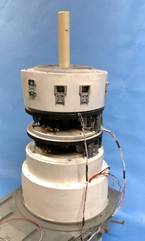
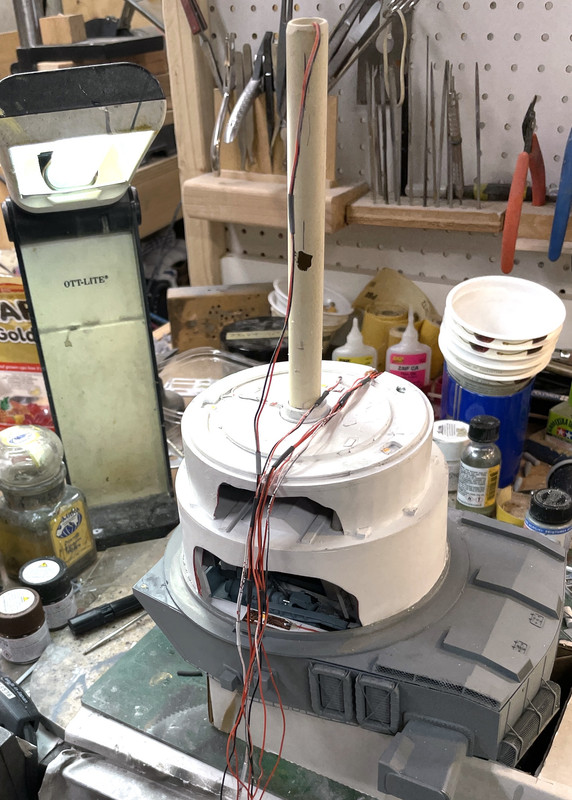
From one angle...

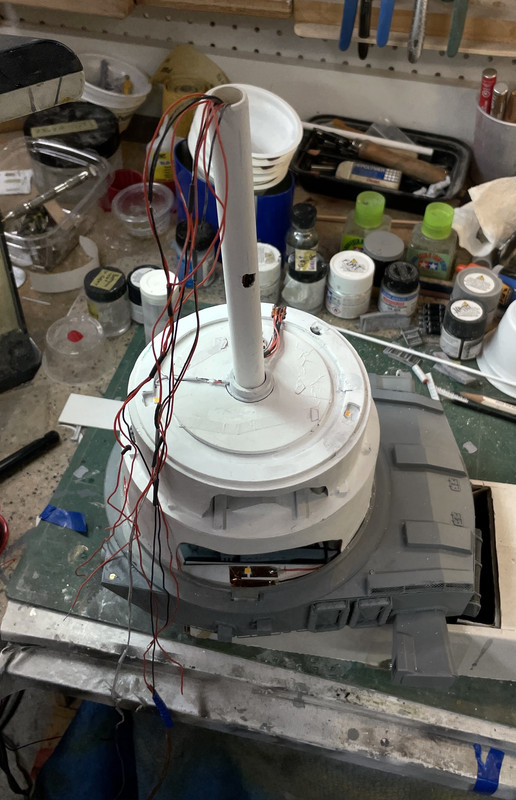
And 90 degrees around. The wiring coming up the back of the electric deck is at the rear and out of view. I also touched up all the flat white that got disturbed when epoxying the pan and e-decks.

And of course something broke. Those $@T)Y)% float net baskets are just too fragile to be around this level of heavy construction. I'm going to wait until it's just about all done and reinstall it.

Tomrrow will see the stack come together. I really think I need to build the enclosure BEFORE the stack is fastened to the base. I'm going to have to trial fit everything and don't want the chance to bump something. So I will be building the case sooner rather than later. Actually installing the stack into the base will only take a couple of minutes. Since I have to terminate all those LED wires with the model built and on the base, I will also like the enclosure built so I can tip the entire model on it's side or upside down without the model supporting any of that weight. Speaking of weight, resin is heavier than a styrene model. Between the mass of the base, the acres of 1/16" plexiglass and the dense model, this thing's going to be heavy!

Stay tuned!


  • Member since
    January 2021
  • From: SW Florida
Posted by fuzznoggin on Tuesday, December 20, 2022 6:51 AM

I am just aswestruck at the cailber of workmanship you are putting into this project!  I really can't wait to see the results.  Definitely will be an award winning piece Bow Down

  • Member since
    October 2019
  • From: New Braunfels, Texas
Posted by Tanker-Builder on Tuesday, December 20, 2022 7:52 AM

Hey!

       That looks like it is going to be as heavy as a radio controlled Log loading Machine I built for a personal injury Atty. years ago. It had to be big enough to hold a 'Ken" figurine and all the R.C. gear to do what it did in miniature that it did killing the operator in real life. The machine sat on a base and it was at least 150 lbs. Oh and I found printed material is not light! My H.O. scale Round L.N.G. Storage tanks are seven ounces each!

  • Member since
    March 2012
  • From: Louisville, KY
Posted by Builder 2010 on Tuesday, December 20, 2022 10:18 PM

Yup, it's heavy, but not that heavy.

As I noted yesterday, the end game moves fast. I built the stack only to find out that the ladder rung assemblies just weren't going to go in. The headroom is so tiny that they would go unnoticed. The fit betwen the column holes in the decks and the column o.d. that my paint job created a bind that was so tight that it removed all the paint as I got the decks down into position. I don't want to have to pull those decks off the column to open the holes a bit, so if the paint really matters I'll have to do some touch up painting in situ, and I'm not looking forward to that. But I got all the decks stacked and all the wires threaded through the column. It's now wating for the cabinetry to fully cure (tomorrow) for insertion into the base. It's still sitting upside down.

I am not gluing the lower three decks to the column or each other. The column will be secured in the flange below the base so it can't lift up, and having some flexibility in positioning could be beneficial, especially when fitting in the shells.

And my column WAS NOT PLUMB. I cracked the epoxy joint, made a couple custom squares with relief cuts to get around the e-decks flange, and cross-plumned it. While holding it, I let a little thin CA down into the joint between the now-hard epoxy and the part. It cured quickly.

I haven't tested any lighting after this this abusive pulling in getting everything threaded. We'll all find out together what lights are still working.

I then built the Plexiglass enclosure. I followed all my new-learned techniques for successfully gluing Plexiglass, and it would have been perfect. It came out almost perfect. When I first started assembling the shapes I used the corner clamps that I use for gluing model railroad buildings. I also used my machinist squares to ensure the sides were square.

Before doing any of this I removed all the plastic protective film (tip number one) since it just get in the way. I also used a razor to scrape a very small bevel on the gluing side of the edge (tip 2). I then, using a Q-tip, layed down a thin film of solvent on the glue edges to help flow the adhesive into the joint without entrained air bubbles (tip 3). I then applied the solvent by holding the applicator upright and squeezing the air out, turning it over and slowly let some air in so the drips don't come out (tip 4) and laid the pieces on wet towels to help kill the static build up that can attract the cement. (tip 5).

I realized that I forgot to tape the edges together, which I did, but didn't remove the corner clamps. It was one of those corner clamps that absorbed the cement in the foam gripper and soaked a bit of the Plexi and damaged it. It will be in the back and it's a bottom corner and it don't think I can do much to fix it. I could try polishing it out, and may if I have the time. This image was after gluing and when I turned it over. I glue it up sitting on the lid and was very happy that all the edges coincided as they should.

After pulling the tape and cleaning off any excess tape goo, I got this. It fits nice and loosely on the base which I wanted. i didn't want any binding when opening and closing.

I put the graphics on the back of the rear panel holding by static charge to see how it would work. 

The model won't block these much so I may go with this idea. My genius #1 grandson suggested to do something different with the text, and as I usually do, I will take his lead. He's graduating U of IL engineering and already has a nice job. It's takes a while for acrylic joints to fully cure, so by tomorrow I can handle it. I'm going to insert the model into the base tomorrow and do the wiring. I tried the deck piece and guess what? It doesn't work. I designed the entire model without this part in place. I would have to remove about 1/4" of the outer shells and the odds of that happening are zero to none. The model works just fine without the main deck and it would cast shadows on what is below it and that's not so good. I just bought a ton of Northeastern Stripwood to make a real wood deck and I don't have to worry about that now.

I started working on putting some trim around the vents and will finish tomorrow. The boys were in from college and we had a nice Hanukkah dinner at my daughter's house tonight.


If there are no more catastropes I think I will basically have a finished model by tomorrow at quitting time. Yesterday I dropped one of the projectile decks on the concrete floor and it made a terrible "crunching" sound. There are very few times where I praise the brittleness of CA adhesives, but this was one of them. Everything that was CA'd just popped off without any resin breaking. I glued everything back together again and did some touchup painting and it was good to go. I don't want anymore of those things happening any longer.


  • Member since
    January 2021
Posted by JoeSMG on Wednesday, December 21, 2022 5:08 PM

That is a great looking case, I've been meaning to learn how to make them, so thank you for the list of tips. What is the adhesive you use to set the plexi? I didn't see it mentioned.

Glad the fumble cost you little - at this point in a project those types of setbacks can be so agrivating.

Fingers crossed for you on the lighting - I'm looking forward to seeing that feature on the completed display.

- Joe the SMG

  • Member since
    August 2007
  • From: back country of SO-CAL, at the birth place of Naval Aviation
Posted by DUSTER on Thursday, December 22, 2022 12:41 AM

So close, Lookn' so good.

Steve

Building the perfect model---just not quite yet  Confused

  • Member since
    March 2012
  • From: Louisville, KY
Posted by Builder 2010 on Thursday, December 22, 2022 9:51 AM

i keep getting a "403 Forbidden" error when trying to post last nights images. The model was mounted with some difficulty and is effectively done. Today, I made locks for the case based on a suggestion of one of my other forum readers (an Austrailian). He suggested making a way to fasten the enclosure to keep the model more secure. It really helped today as I was able to tip the whole deal over on its side so I could solder all the leads on the bottom without having any pressure on the model. 

I'm going to attach just one image from yesterday to see if the post uploads. There may be something corrupt in the post that I'll have to find. The same post loaded successfully on three other forums.

If the test works I'll do more and today's post. 

  • Member since
    March 2012
  • From: Louisville, KY
Posted by Builder 2010 on Thursday, December 22, 2022 5:42 PM

Well that worked!

But sending a copy of the post from on of the other Forums just failed again. Instead of re-writting the whole thing...AGAIN... please go to this URL and read it.

https://forums.kitmaker.net/t/takom-iowa-class-mark-7-16-50cal-turret-with-full-interior-start-to-finish/16832/269

Meanwhile, I'll post today's work which also was MONUMENTAL. Well maybe not quite monumental, but it was at least biblical. It was a Hanukkah miracle in that ALL the LEDs worked! That's with pulling on the wiring harness all day yesterday to fish the wires to the bottom, pull them back partially to fix a near disaster, and the pull them back down again.

Today I built the case fasteners that secure the case. It secured it so well that I could tip over the model and do all the soldering, without putting any lateral pressure on the delicate model.

I bought a strip of 1/2" brass, shaped it to conform around the base's ogee curve drilled it for the hardware and mounted it on holes drilled in the plexiglass. I have a few drilled sharpened for acrylic drilling. This is essential. A standard 135 degree drill point will bind on exiting the hole and 50/50 will fracture the valuable plexiglass.

 With the case secured I had to prepare my primary work surface to hold the model lying down. I put a damp towell down to kill any static charge that would attract the clouds of dust that are contained on that workbench. This used to be where I did active building, but for the past couple of years, I use my IKEA roll-around bench mostly, and the big bench became a catch-all...but not today. That dirty tray in the front is my attempt to replicate a jeweler's work bench belly tray to catch stuff that's heading south. It works!

I gingerly laid the model over on its side and was rewarded with nothing on the model moving or falling off. This neatly exposed the belly for wiring hookup.

This is the mass of wiring coming down from the nine LED circuits. I had no idea if they were all intact after all the manhandling. I did periodically test them during all the other build steps when I was still able to made corrections if necessary.

I needed to tin all the leads before circuit board insertion and did so en masse. BTW: that Panavise with the wire loom dates back to 1975 when I was training about 1,000 people on precision electronic soldering. It was one of my gifrs from the program. And I've put it to great use ever since.

I inserted one red lead next to the CL2N3 LED driver and the other black lead onto the ground bus and soldered them. I had no idea what circuit this was but I was eager to test it. And EUREKA! it's ALIVE!

With that encouragement I terminated the rest of the bundle and powered it again. And once again, I was very pleased that every circuit lit as it was supposed to.

It was truly a Hanukkah miracle, which after all, is considered the "Festival of Lights".

All that was left was to re-attach the circuit board on its standoffs and dress the wiring bundle.

The last thing I did was affix the "Builder's Plate" making the build official.

I put the model back on the photo stand and took some more images. I will take another set when the graphics are mounted on the case, and that, as they say, is that.

The case screws are loose since I will have to remove it tomorrow to install the graphics. The curator asked me today "how much time did it take?" I have not kept an accurate time log since I wasn't billing anyone for this, but I estimate somewhere between 400 and 500 hours. Drawing time alone was probably 100 hours. If I was going to do it for fee, even at $20 and hour, we're talking $10k. It's why it's hard to make a living making models. If any other museum ship wants one, I'm going to have to charge them something for it. In the next post... the last one for this project, I'm going to try and list all the things that went right and those that didn't and the lessons learned. If I'm ever doing another I want to make it a lot easier.


  • Member since
    May 2009
  • From: Poland
Posted by Pawel on Thursday, December 22, 2022 5:43 PM

Hello!

Just that picture looks very good!

I was talking with my family today, I told them: I've been trying to build a tank with interior a few times and so far I was unable to make it... Now you pulled off something more complcated than a tank - that gives me hope for the future!

Good luck on the home stretch and have a nice day

Paweł

All comments and critique welcomed. Thanks for your honest opinions!

www.vietnam.net.pl

  • Member since
    August 2007
  • From: back country of SO-CAL, at the birth place of Naval Aviation
Posted by DUSTER on Thursday, December 22, 2022 10:04 PM

Builder 2010

Test


You passed 

Steve

Building the perfect model---just not quite yet  Confused

  • Member since
    October 2019
  • From: New Braunfels, Texas
Posted by Tanker-Builder on Friday, December 23, 2022 8:13 AM

Hey! Builder2010!!

      It's good that you learned early. Building models for a living requires many compromises in the craft that you wouldn't stand for your own models. That's why you don't see more folks doing it! When you do such as you have with such attention to detail and in a crunch then it dawns on you, "Hey" ,You say to yourself, "This ain't fun anymore."

      Building Models for a living sometimes does result in a jaded look at the world. It is an art! It does NOT lend itself to the One man, or One woman, my rules, My shop! When you quote for a job, folks look at you like, " What, is he/she nuts" "We're talking about a stinking Toy almost".

     Sadly, That is what most folks see a model as, as unique, But not to useful( you can only look at it right?) I the world of museums and education(some Venues) they are seen as tools, for marketing or teaching. This holds true for industry as well.That's why graphics programs on computers with three dimensional abilities have done so much better. You only need the computer, a program and the time to draw it up.

      The downside to that is simple and hits most where it hurts,The pocketbook! Some things can ONLY be represented with a real detailed Miniature to look at, feel, and see, in all types of light. But, by their very Nature they are expensive! Whethet 3-d printed or scratch built and wired. It takes knowledge and an ability to translate drawings and written descriptions to a  scratch bult Model of the real thing. Few of us have the inclination to do this when you count the number of souls on the planet!!!

      Although you almost lost me a few times, you did it! You captured my attention and Made me look because I couldn"t believe what I was seeing! WELL DONE!!!!!


  • Member since
    March 2018
  • From: Chicago suburbs
Posted by Luvspinball on Friday, December 23, 2022 12:05 PM

Myles,

First off, incredible build with so much useful information for all of us.  Love the way you incorporated all your lighting into a board for easier control of the wiring.  For those looking to do the same, but want to be able to control which circuits are on, you can buy and use dip switches (from computer boards and CPUs) to hide small, accessible switches.

If you do need to do this again, at least you have most of the pre-production files you will need.  I know you tweeked them several times, which was part of the learning process of what is (and isn't) feasible when 3D printing.  Can't wait to see your "lessons learned" post in hopes of avoiding some of the issues you faced during this build.  While I don't plan on trying to repeat this build of yours (which would probably be darn near impossible), your insights will be valuable to many builders for years to come.  I think you should re-post or link this build on the diorama page, since many folks wouldn't think to find something like this under the ships page.

Again, a fabulous job.

Bob

Bob Frysztak

Luvspinball

Current builds:  Revell 1/96 USS Constitution with extensive scratch building

  • Member since
    January 2015
Posted by TheMongoose on Friday, December 23, 2022 11:06 PM

Just absolutely incredible! Dang they are going to be stoked when they see it. Bet you're thinking about how to drive it out there rather than ship it after all this!

In the pattern: Scale Shipyard's 1/48 Balao Class Sub! leaning out the list...NOT! Ha, added to it again - Viper MkVii, 1/32 THUD & F-15J plus a weekend madness build!

  • Member since
    August 2007
  • From: back country of SO-CAL, at the birth place of Naval Aviation
Posted by DUSTER on Friday, December 23, 2022 11:21 PM

I have said it before and as have others, in various ways, WOW!

So much of the information you have shared will indeed inspire myself and others to begin to move out of the dreary comfort zone and into the Exciting Creating Zone.

Steve

Building the perfect model---just not quite yet  Confused

  • Member since
    March 2012
  • From: Louisville, KY
Posted by Builder 2010 on Saturday, December 24, 2022 1:35 PM

I just spent an hour responding to all of your wonderful comments and my MacBook Pro decided to reload the page and wiped out the entire post. Yikes!!! So I have to do it again since it was soooo well composed.

I really appreciate the fine words. It makes all the writing worth it. I've said it too many times that I get as much out of posting as I get back from the readers. Really! Not only does the positive reinforcement keep me going on a year-long project, but I get direct support and ideas from great modelers literally from all over the planet. I post this same thread on four forums each with different audiences. I do this one first because, frankly, the image posting system sucks, whereas I can simply copy and paste the entire post into the other three with no image fussing. If I do have to add an image to them, I can click and drag it directly from my file folder, whereas here I have to upload everything onto a photo site and then copy that URL to the image dialog box.

I've sent off an eMail to Aaron Skinner, the editor of this fine magaizine to ask him about publishing about this project in FSM. I also commented, that while commendable to publish two short articles on 3D printing in the currect issue of FSM, the article barely scratch the surface of what you really need to know when producing detail parts for our models. I offered to give him something more. Encouragement from my followers would be appreciated.

This project couldn't have been accomplished without the help of others. It really does take a village. Special thanks go to Ryan Syzmanski, the Big J's curator, who not only got me some critical measurements that I needed just to get started, but also the special tour I took where I got access to the non-public areas and did those amazing 3D scans with my iPhone 12 Pro. The other person is Jim Slade. Jim is doing the near impossible. He's making 3D CAD drawings of every frame of the Iowa ships based on the actual engineering drawings that are on microfilm at the National Archives. He gave me those accurate drawings of the pan and electric decks and the outer bulkheads. Without them I was completely lost.

Here's the final, final images. I redid the graphics to my grandson's approval and produced them to look like the placards that adorn the guns and gun compartments. I did the faux frames in CorelDraw.

Now for the "After Action Report"

The Good!

  1. Getting it finished where it actually exceeds my expectations. That's really not that hard since I expected nothing in the beginning.
  2. Creating a very good rendition of the complicated and elusive Mark 7 16"-50 cal gun including the tiniest details of the massive yoke and breach.
  3. Designing and pre-installing all the surface mount LED lighting and the use of the circuit board to contain the nine CL2N3 LED drivers making hookup fast and error free.
  4. All the lights working after all the yanking and pulling I did to assemble the beast. The true Hanukkah Miracle of Lights!
  5. Machining the back ends of the after-market aluminum gun barrels to 7/16" so I could produce the resin gun slides with sufficient wall thickness with the mating part of the gun slides to support the guns
  6. Finally figuring a way to print the entire gun slide assembly in two parts (yoke and slide) fianlly resulting in a warp-free product.
  7. SketchUp's ability to produce an accurate flattened-out shape which enabled me to get the circular bulkheads made out of styrene with minimal guessing.
  8. My iPhone 12 Pro's LIDAR which enabled me to 3D scan the projectile hoists and lower powder hoist areas answering some major questions
  9. My special private tour of the ship where I finally could figure out the nooks and crannies in the gun compartments and surrounding area.
  10. Nailing the detail painting.
  11. The intricacy and beauty of the long-base range finder and how close it is to the prototype.
  12. Producing really small details in 1/72 like the powder scuttles, the inside periscopes, the auxiliary computer and all the pumps and machinery on the e-deck and elsewhere.
  13. How well the roller bearing/ring gear came out... finally.
  14. The stunning piece of furniture upon which the model sits crafted by one of my oldest friends and bass player from my college R&B band, Bryant Mitchell.
  15. Even though it was an awful experience, the way the open bulkheads worked out as a way to display the innards of this complex machine.
  16. Mastering the creation of a large Plexiglass enclosure with a minimum of screwups... which is a first for me. Had extra help with all the good advice.
  17. How the graphics finally turned out with my grandson's input. The kid's terrific!
  18. How the metal guns really highlight the turret.
  19. Getting the elevating screws reasonably right... still not perfect.
  20. And finally, having the tools, skills, know-how and physical faculties at 77 to pull this off.

The Bad!

  1. Having to produce the detail that would be on the back side of the officer's booth bulkhead on a separate piece that is the rear gun compartment. This was necessary as a function of the 3D printing process to avoid supports on details that would have been wrecked by them. It complicated the build.
  2. Not drawing the plastic parts in the SketchUp modeling. This came back to bite me right at the end with things like the decking no fitting on the model (among other things)
  3. Starting the drawing process with little or no dimensions only having to redraw-reprint more times than I'd like to mention.
  4. Attempting to 3D print the thin circular bulkheads on the lower decks. 3D printing doesn't like thin sections.
  5. The inaccuracy of tracing part foot prints on non-dimensioned illustrations. Some of my equipment is probably overscale due to how tightly things ended up fitting.
  6. Having to make the annular decks into 1/4" thick assesmblies to resist the constant stress of the styrene circular bulkheads trying to straighten themselves out. Besides stressing glue joints that kept popping, the thick decks created assembly challenges at the end.
  7. Specing the central column holes too close to the column's diameter. They didn't have to be press fits.
  8. Making the cradle assemblies too close to prototype proportions leading to constant breakage and three reprints.
  9. Not having a good idea of how some of the parts would assemble in the real world when drawing them, necessitating lots of custom fitting.
  10. The constant repainting caused by the late changes.

The Ugly!

  1. That collosal error of assembling the armor barbette at the wrong height and having to almost destroy it to fix it.
  2. The printing of the ring gear wrongly only to find this out when I was fixing #1.
  3. The final misalignment of the projectile flats with their respective annual decks. Maybe people won't mind, but I do. This is due in part to the thick annular rings problem.
  4. Getting the spacing wrong between the guns on the gun girder. This caused lots of problems. And that was the 3rd girder I printed.
  5. Not having a clue about how long the elevating screws really needed to be and still not happy with the installation.
  6. Having to redo the side sighting compartment designs and the telescopes due to not understanding the geometry.
  7. Painting the central column only to have it all scrape off as I manhandled it into position and then touch it up two times reaching into the model.
  8. Reprinting and breaking the back bulkhead three times.
  9. Getting the long-base rangefinder optical ends too short, again becasue I didn't draw the actual plastic parts when doing the design. I took my lengths from line drawings.
  10. Dropping important things on the floor and having to repair them too many times.
  11. Screw up the projectile hoist fits right to the end.
  12. Relying on CA to hold stuff when it's totally unreliable, especially gluing styrene to resin.
  13. Having the audacity to think I could create this thing and almost not making it.


  • Member since
    April 2003
  • From: USA
Posted by keavdog on Saturday, December 24, 2022 1:52 PM

I can't say enough about this Myles.  That is just fantastic.  Watching all the bits come togther was fun, but seeing the finished product in that awesome display is truely amazing.  This should be on board the USS Iowa museum in LA.  Masterful work.

Thanks,

John

  • Member since
    March 2012
  • From: Louisville, KY
Posted by Builder 2010 on Saturday, December 24, 2022 5:24 PM

Thank you!

I've had similar thoughts, although getting it to San Diego isn't as easy as driving it to New Jersey. I really can't give any more of them away, and I don't have a clue what a museum ship would be willing to pay for it. We'll see if any demand develops after the other ships learn about its existence.

I was able to generate the QR code tag on CorelDraw 2021. It's easy and quite amazing. I'll put this tag on the lower left front corner of the enclosure. It leads folks to the KitMaker Forum. I chose that as it very easy to navigate... it's just one continuous page and don't need password to read, just to contribute.

  • Member since
    January 2021
Posted by JoeSMG on Sunday, December 25, 2022 10:02 AM

Builder2010, thanks for sharing your progress through this incredibly ambitious project. Hats off to your tenacity and skill, it came out beautifully.

- Joe the SMG

  • Member since
    August 2007
  • From: back country of SO-CAL, at the birth place of Naval Aviation
Posted by DUSTER on Monday, December 26, 2022 12:23 AM
Bow Down Congratulations on completing such an incredible model. It has been my pleasure to watch as you created, recreated, and just plain “imagin-ered” your way out of challenges and near disasters. All the while keeping up an in depth monograph.  Which provided a massive, in my case, amount of learning, about  new equipment and old standard techniques.   
All that said, what is the next? A 1/72 scale model of the bridge for the Iowa class? Perhaps a 1/72 scale model of the engine rooms? Or__________ well, you fill in the blank  Angel

Steve

Building the perfect model---just not quite yet  Confused

  • Member since
    March 2012
  • From: Louisville, KY
Posted by Builder 2010 on Monday, December 26, 2022 9:50 AM

Thanks for the great comments! What's next? I have a custom building for the railroad that is waiting for me to laser cut the walls. I was about to do this when my CorelDraw 2017 stopped booting up. I had to run it on a Windows emulator on my MacBook Pro, and either Windows or the VM Fusion emulator upgraded and Corel stopped working. The public laser cutters at the University of Louisville's First Build Makery, use Adobe Illustrator. CorelDraw does a good conversion to AI, but none of the other converters I found worked. They reproduced the outer cut lines, but ignored all the brick work. Over Thanksgiving my son and daughter in law bought me CorelDraw 2021 for MAC. Yes... Corel finally ported their terrific program for Mac. I have now translated the files and will be cutitng after the holidays.

This building in Newtown, PA, was originally constructed as a hardware store on the left side and dry goods store on the right in 1869. Later, the hardware store expanded into the dry good spaces as it remains today. It is a national landmark and an ACE Hardware store. 

Story has it that in 1899, burglars attempted to blow the safe with dynamite and blew up the building instead. It burned to the ground and was rebuilt to the former design with only some minor changes to the pediment. The safe still remains behind the counter. Much of the shelving and cubbies are from the 1899 bebuild. My design is the scale width, but slightly shorter to fit into the space on my layout.

The actual lot on which it sits slopes down almost a full story so there is a cellar entrance in back. My design reflects that my site is flat. I may make two of these and give one to the store for display. They took some detail pictures of things for me. I have all the architectural goodies already 3D printed, and have the laser cut windows and thin trim. I may reprint some parts as the originals were done on my less capable Elegoo Mars Classic. My new Mars 3 has 8x the X-Y resolution and just does a better job.

Re: the Iowas. The bridge is simple compared to the turret's complexity, but an engine room... Hmmmmm.... That might be fun and very challenging. I've visited an engine room on the Alabama, and they are very complex. Finding documention would be a challenge too. I'll talk with Ryan and see what's available and if there's any interest. The public can look into the nav bridge, but I don't know if they're able to get into the engineering spaces and therefore a model might be of interesst. Even one engine room would be a large model extending the full width of the ship within the armored citidal.

And then there's the possibilty that one of the other ships would want a turret model. If I were to build it again, I would seriously think about making the outer cylindrical parts out of brass and not styrene. I'm a decent metalworker and very good solderer. I have access to a professional sheet metal shop where I could roll the forms. And they would stay together for the long haul. In metal, the annular decks could be prototypically thin and soldered to the curved walls. Even as half shells the shapes would be stable.

  • Member since
    May 2009
  • From: Poland
Posted by Pawel on Monday, December 26, 2022 4:46 PM

Hello!

I already expressed my admiration for this project, but I would like to congratulate on finishing it!

You mentioned mutliple times how the sheet styrene gave you problems trying to straighten up after being curved. I believe you wouldn't have this problem if you bent the parts around a cylinder of similar diameter and then heated the styrene sheet. I'm pretty sure that would make the bend permanent and save you a lot of problems.

Making the sides sheet metal would probably work, too, but I think it could bring new challenges with it - soldering big parts like that is doable but needs a lot of heat, and often needs a cleanup afterwards, and after you attach any plastic parts to the model the heat can potentially destroy them, together with the paint job. Making the cutouts would also be harder than in styrene - so I'm not so sure if it would really make the build that much easier - but heavier, for sure. You would also have to be extra cautious for shorts when it comes to the lighting...

Anyhow, good luck with your future builds, looking forward to seeing you post a new thread here on the forums!

Paweł

All comments and critique welcomed. Thanks for your honest opinions!

www.vietnam.net.pl

  • Member since
    August 2007
  • From: back country of SO-CAL, at the birth place of Naval Aviation
Posted by DUSTER on Wednesday, December 28, 2022 10:57 PM

Builder 2010
Re: the Iowas. The bridge is simple compared to the turret's complexity, but an engine room... Hmmmmm.... That might be fun and very challenging. I've visited an engine room on the Alabama, and they are very complex. Finding documention would be a challenge too. I'll talk with Ryan and see what's available and if there's any interest. The public can look into the nav bridge, but I don't know if they're able to get into the engineering spaces and therefore a model might be of interesst. Even one engine room would be a large model extending the full width of the ship within the armored citidal.

  LOL I was being a smart-aleck about the bridge.  Though the engine room could be an interesting option, at some future date. 

 Your RR building looks to be another interesting production. Will we be able to “look over your shoulder” as this project comes together?

Regardless, Stay Well and enjoy your upgraded CorelDraw. Back in the last century I used PaintShopPro by Jasc Software, Inc, before Corel acquired them. I can only imagine advances in the Corel products, since those long ago days.


Steve

Building the perfect model---just not quite yet  Confused

  • Member since
    March 2012
  • From: Louisville, KY
Posted by Builder 2010 on Thursday, December 29, 2022 8:38 PM

I've been posting a full rendition of the railroad build for 10 years with all my usual embellishments. You can follow it right here. I when I say full rendition, I mean FULL RENDITION! Everything.

https://ogrforum.ogaugerr.com/topic/continuing-saga-of-the-pandampprr

Re: bending the styrene. I've had not-so-good luck heating styrene to bend it. If you overheat it just a tiny bit it warps all over the place. I'd have to find a way to heat it gradally and under control. Metal soldering is not a problem for me. But gluing resin parts to metal might be a problelm. I've been thinking about better ways to tie the annual rings to make them more secure. 

Now to the good stuff. 

The model made it from Louisville, KY to the curator's cabin in PERFECT SHAPE! Nothing fell off! I brought a box of emergency tools and glue just in case, but didn't need them. What I did do is forget them when I left and Ryan's going to have to ship them to me.

Ryan was impressed and it exceeded his expectations. 

These pictures were taken by my younger and stronger nephew who did the honors of carrying the model to the ship and down the companion way ladder to Ryan's office. We discussed where it should be displayed and decided the ward room probably would work. It's the place where Anyone with a disabilities can go to the wardroom and get educated about the ship. I also asked if he communicates with curators in the other three Iowa museum ships? Yes! And they might be interested to have a model of their own. These would not be donated and shipping would become a challenge. I could drive a model to the Winsconsin in Norfolk, but Iowa in San Pedro and Missouri in Pearl is another story.

We spent about a half hour with me explaining the fun and challenges of building a one-off custom model. Ryan is a model maker himself so had no trouble empathizing with the challenges.

And more news. Aaron Skinner responded and said FSM would like to publish an article about it. He gave me some requests which I will comply with. I've already started writing an article, but already have way too many words.

It was a very good day! The fact that the model made it to the ship in perfect condition was a real joy.

When the model is in it's final position I will post that also. Stay tuned.


  • Member since
    August 2007
  • From: back country of SO-CAL, at the birth place of Naval Aviation
Posted by DUSTER on Thursday, December 29, 2022 9:52 PM

Steve

Building the perfect model---just not quite yet  Confused

  • Member since
    March 2013
Posted by LonCray on Friday, December 30, 2022 7:06 AM

Watching this beast come together - including the fits and starts as you figured out new and better ways of doing things nobody has done since they built the last 1:1 battleship - has been one of the most satisfying stories this entire year.  Bravo sir!  I have been to USS New Jersey twice (and Wisconsin and Missouri once apiece) and now I need to go a third time just to see your creation in all her glory.  

  • Member since
    March 2012
  • From: Louisville, KY
Posted by Builder 2010 on Friday, December 30, 2022 8:58 AM

Many thanks! I will keep everyone posted when and where it's on final display. Ryan informed me later yesterday that it's being photographed and catalogued before placing it. The ship is technically owned by the State of New Jersey and the donation process is fairly formalzed.

  • Member since
    March 2012
  • From: Louisville, KY
Posted by Builder 2010 on Friday, January 13, 2023 3:16 PM

The model's in its "almost" final position. The ship is closed to the public until March, but they were having a board meeting and Ryan wanted them to see it. It is now on temproary display in the ward room. It's sitting on an end table between two couches and it's not a secure place. It's eventually going onto the bookcase in the background... a much better location.

The board members were not told that I was building this model and were duly impressed.

Ryan's also going to see if he can get some higher resolution images for me.

Now you're all up to date.

  • Member since
    March 2009
  • From: brisbane australia
Posted by surfsup on Friday, January 13, 2023 8:35 PM

Just simply stunning work. I am in awe.....Cheers Mark

If i was your wife, i'd poison your tea! If Iwas your husband, I would drink it! WINSTON CHURCHILL

JOIN OUR COMMUNITY!

Our community is FREE to join. To participate you must either login or register for an account.

SEARCH FORUMS
FREE NEWSLETTER
By signing up you may also receive reader surveys and occasional special offers. We do not sell, rent or trade our email lists. View our Privacy Policy.