Thank you! Feedback like that keeps me going.
I got confirmation from Airfix that Sprue M is in the mail and will arrive next week. That solves that problem. Meanwhile, I started construction of that remarkable Napier Saber power plant. I read a white paper on the difference in performance between sleeve and poppet valved aero engines. I was wondering just how sleeve valves worked in this instance. I thought the Saber was the only engine with this arrangement, but UK's Bristol Radial engines also used them, which describes why they look different with their exhaust stacks coming out of the middle of the cylinder.
The sleeve actually performed dual functions. It served as the working cylinder liner in which the piston traveled and it moved simultaneously side to side and slightly up and down to expose and close passages leading in and out of the cylinder for induction and exhaust. Ported engines in 2-stroke are common since the ports can remain static with the piston itself opening and closing them. But 4-strokes have to close off induction and exhaust at different points in the cycle and this requires more motion.
Sleeve engines claimed to have less moving parts, but in the case of the Bristol Centaurus (used in the Hawker Sea Fury), it took a gear train of 48 spur gears to drive the actuating mechanism to both rotate and raise the sleeve. Because the sleeve formed an additional layer between the cylinder jug and the piston, cooling was a challenge, but like other engines, as it evolved these problems were genearally solved.
The motion was controlled by a small cam-like lever that jutted out below the cylinder jug and contacted a ring at the bottom of the sleeve. As the cam lever rotated 360 degrees it rotated and raised the sleeve into its various positions. Once the gear train was set up, valve adjustments were no longer needed. This compared favorably to the constant management of valve lash in the contemporary pushrod poppet valved aero engines. The sleeve timing didn't change with temperature, but its diameter would and this would affect operating friction.
There is an Airfix operation to put a motor in this large engine block to spin the prop, but I chose to not do this. I did make sure that the prop shaft is lubricated (Vasoline) so the prop will spin freely.
Between the inner framing and the mass of the plastic parts, the engine block is quite solid. Most of the parts fit together perfectly after routine parts cleanup, but the junction between the supecharger induction pipes and their block attachment had a significant gap. I filled this with a combination of Bondic for the larger gaps and Tamiya filler for the lesser.
This is the engine bottom. Even here, you apply two separate pumps. By leaving the entire front skin off, a lot of these details WILL BE visible.
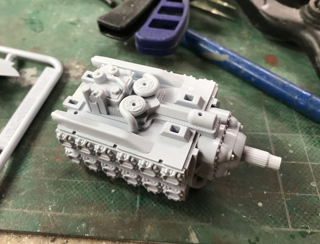
The supercharger is a model in itself with five parts. I used a lot of different sanding devices including a neat powered micro-sander I got from MicroMark. I bought that specifically to clean up resin prints. But another very useful one is the Flexi-sander which is superb for sanding round surfaces such as the induction pipes from the supercharger. By being a soft band it comforms to the curves and gives a great finish.
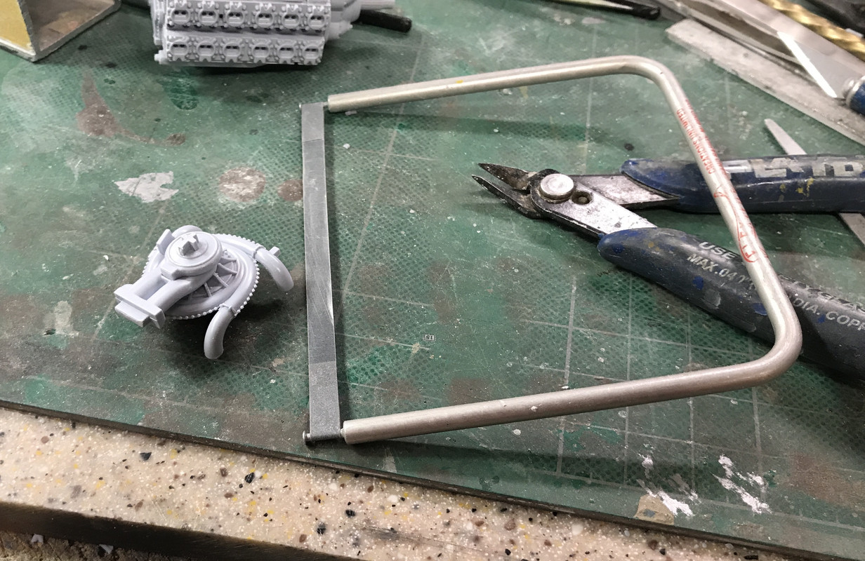
Here are the gaps in the induction system. Two were very large and two were more manageable.
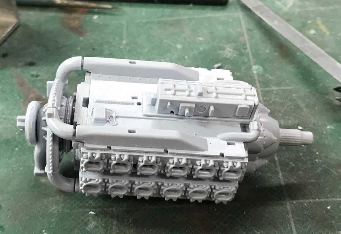
The big gaps were too large for typical fillers so I turned to Bondic. You put it in a layer, harden it for about 5 seconds, put in another layer, and so on until the gap is closed. It's quite hard, much harder than styrene, so you have to sand accurately. If you concentrate on the filler you will get it right. If you need to, apply some masking tape to the styrene from affecting too much styrene.
Here's filled, but not sanded.
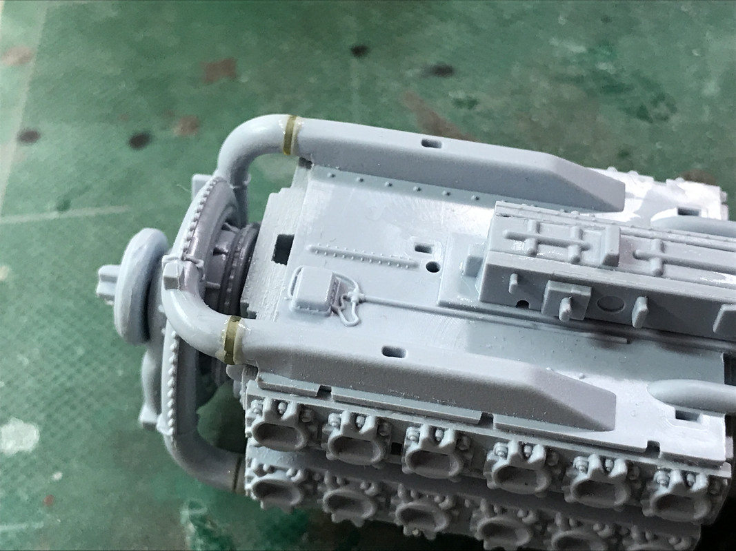
And after finishing:
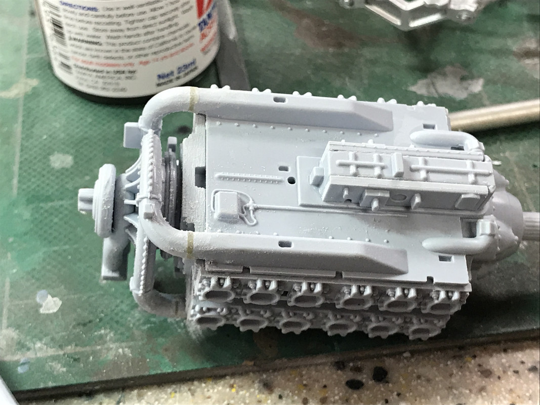
The next step is to install the engine on the airframe before adding any more piping (and there's a lot), but before that it needs to be painted and detailed a bit. While the plans call for black, I'm going with green. It seems all the pictures of extant engines are a nice British Racing Green. Besides, the engine will be fully exposed and, since it's the most interesting part (to me) of this aircraft, the engine's going to be green.
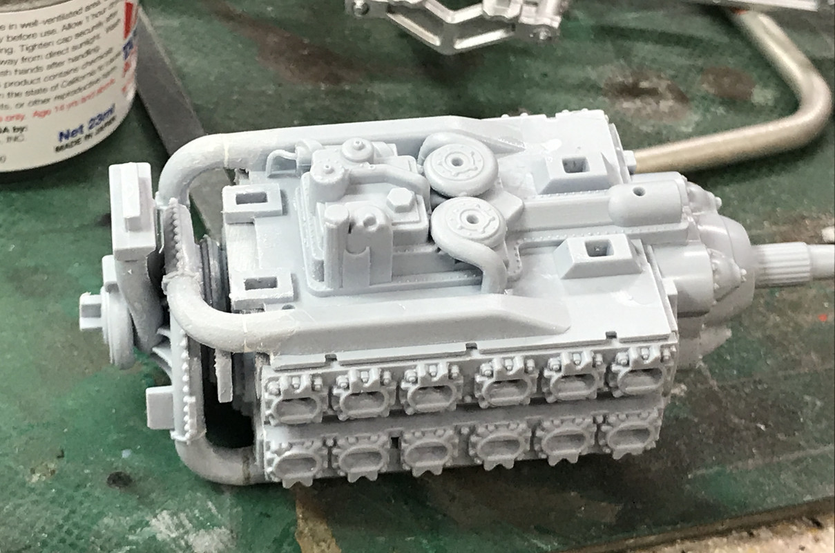
Another clue that this engine's valves are different is that the induction and exhaused enter the side of the block, not the top.