M4 Sherman 75mm Normandy, Dragon # 6511, Setback...
Dear All,
Time for me to start my first build log ![Shock [:O]](/emoticons/icon_smile_shock.gif)
Please excuse the pore quality of the pictures; I hope that I will be able to improve.
This is my first attempt at US WWII AFV's.
I have had a lot off help already from this Forum, I hope you will stay patient with me and continue to provide Your support.
First a couple of immediate issues;
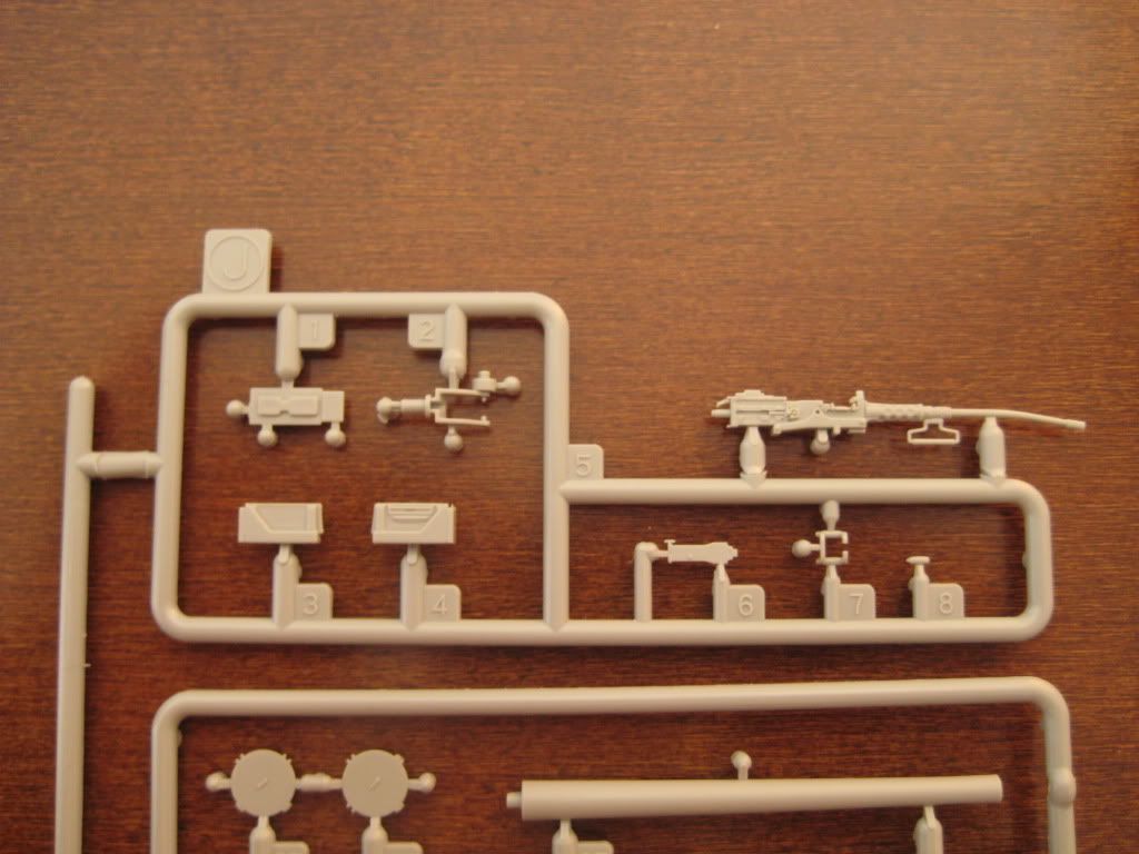
The box is filled to the top with sprues, but the layout of some sprues is a bit awkward.
The M2 is not protected at all, my example came out of the box like this:

The kit provides parts to build three versions of front transmission covers:
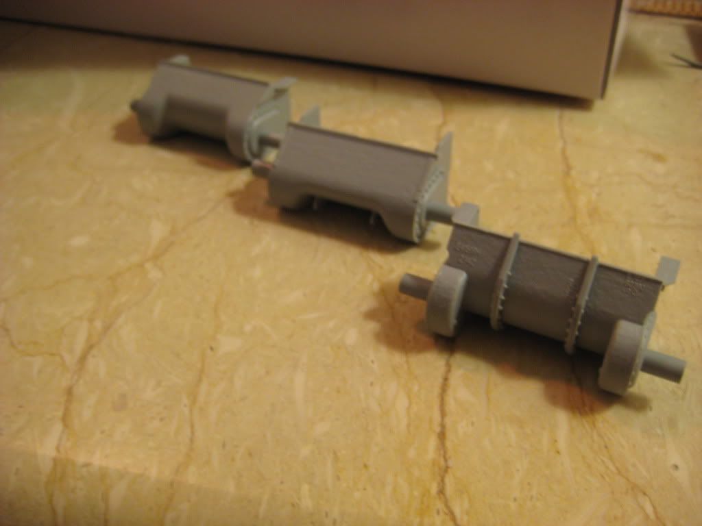
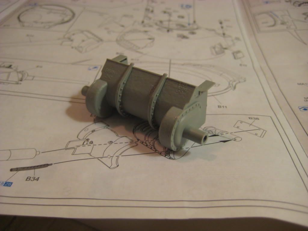
I have opted to go for F1, the box art version:
The lower hull needs an extension to be fitted, parts E3/E4, to close the gap over the running gear and the upper hull.
When building the F3 version you are instructed to cut away 1 mm of this extension part to allow it to fit in the recess in the upper hull:
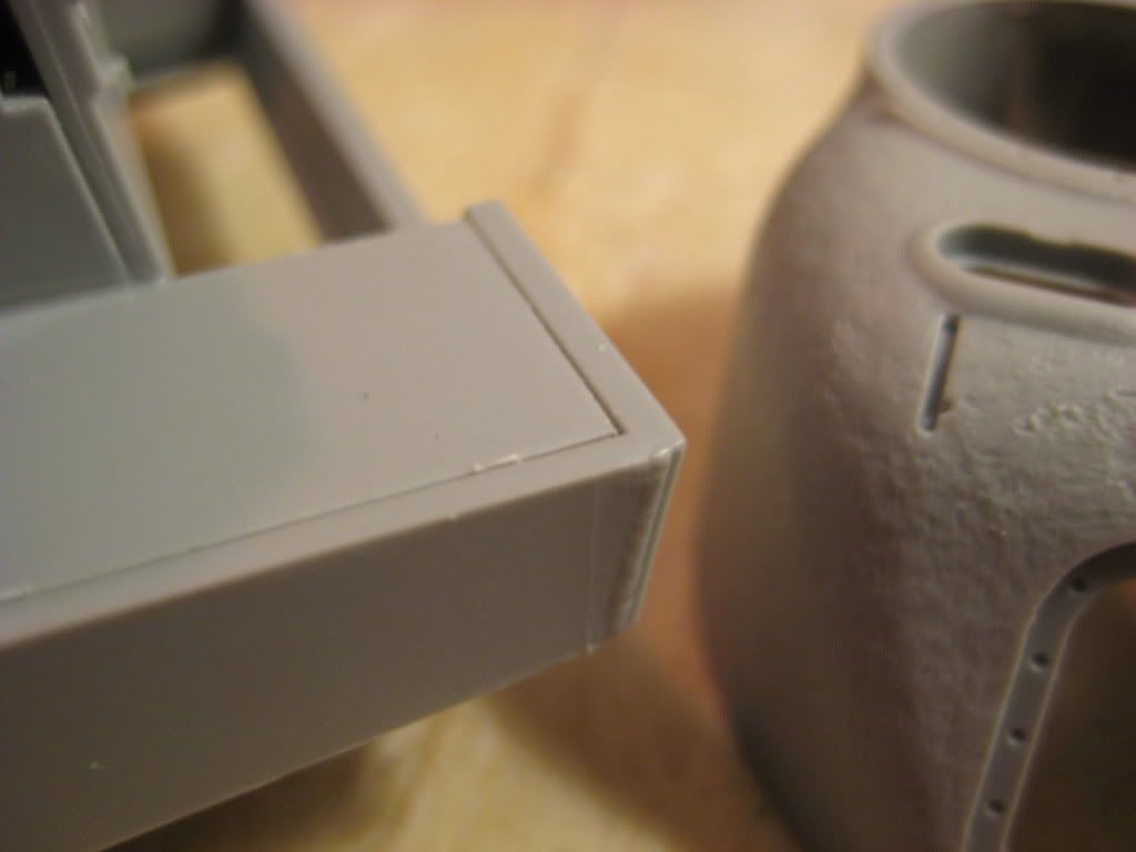
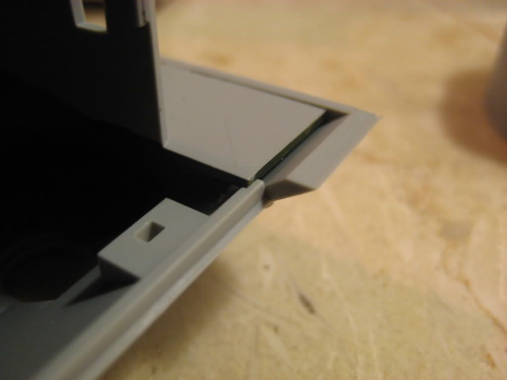
However when building F1 or F2 when you are not supposed to trim these parts the result becomes an overlap in the front of the assembly:
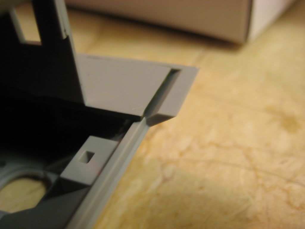
where the lower hull does not correctly fit in the front section resulting in a gap between the transmission cover and the lower hull as such:

You need to cut out the lip in the upper hull to allow the joint, this is not covered in the instructions so take care in this step.
The Turret is very nicely produced with the cast surface looking very convincing.
In the joint between the lower part of the turret (B11) and the upper part (B12) this surface detail is in total absence:
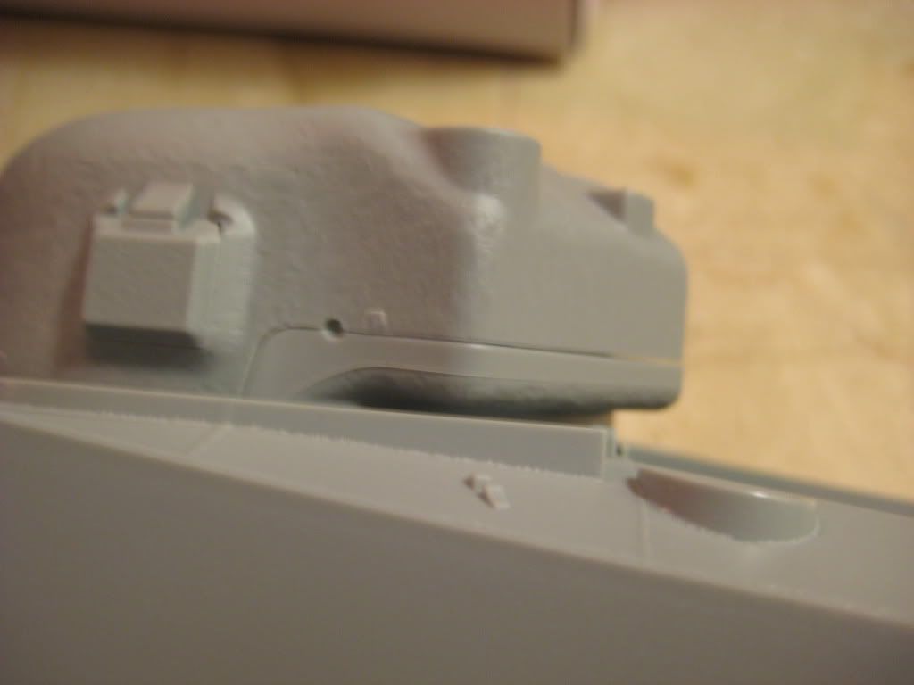
Please provide guidance in this step, is this correct or should I add the cast structure here?
When these issues are sorted I am hoping to make some progress over the weekend and will continue this log on Monday.
With Kind Regards
Utoshita