SEARCH FINESCALE.COM

Enter keywords or a search phrase below:

M3 lee Project 1/6th Scale

34637 views
34 replies
1 rating 2 rating 3 rating 4 rating 5 rating
  • Member since
    September 2006
  • From: Bethlehem PA
Posted by the Baron on Monday, January 25, 2010 11:36 AM

Wow, another excellent job!  Your eye for detail and your ingenuity are outstanding.

The bigger the government, the smaller the citizen.


  • Member since
    October 2009
  • From: South Carolina
Posted by jetmodeler on Saturday, January 23, 2010 6:59 PM

Looks good. Where do you put them things when you are finished with them. You must have really big shelves.Big SmileBig Smile


  • Member since
    April 2005
Posted by armourguy on Saturday, January 23, 2010 6:53 PM

The tank's gallery webpage is complete. The webpage contains all of the construction and diorama pictures that were taken during the build.


http://www.eastcoastarmory.com/m3_lee/olive_oil.htm


With the M3 now out of the way I will be able to focus on my next project. I should have some progress to post on next week  Wink!

  • Member since
    April 2005
Posted by armourguy on Monday, January 18, 2010 4:36 PM

The tank is now finished. I will now be creating the tank's gallery webpage. Once the webpage is complete, and the shop gets a good cleaning I will then start on my next project(s) ;).  


I have added the last of the parts to the tank including the pioneer tools, and the fuel caps.


I have also added the last of the M3 parts to the product line.http://www.eastcoastarmory.com/ustankparts.htm


I have added the large suspension spanner wrench to the US AFV tool set.


The last parts that have been added are the resin Rivet heads. The heads come in two diameters the smaller 5/32nd which are used on the top deck, and the rear plate


and the larger 11/54th which are used for the tank's sides plates.


I took advantage of the good weather and I was able to get some pics of the M3 out doors.


I also made a rendition of a propaganda image that was taken in Fort Knox in 1940


  • Member since
    April 2005
Posted by armourguy on Friday, January 15, 2010 4:04 PM

Thanks Baron. The M3 is now on it tracks, and The tank is now 95% complete.


The DML 30.cal and tripod were painted and weathered. For the 30.cal ammo boxes the kit supplies you with a plastic rod to be used on the box hinges. These rods are very flimsy and a sewing pin was used in its place.


The copula's interior was painted and the copula gun was added.


Most of the tanks details and components have been painted and added. These would include the Antenna, head/ tail light lenses, 30.cal MGs, Air filters, painting the fire extinguisher handles and the grease fittings red.


All that remains now are the fuel caps, and the tank's tools. The tank will then be complete  Big Smile !

  • Member since
    September 2006
  • From: Bethlehem PA
Posted by the Baron on Wednesday, January 13, 2010 2:09 PM

I thought so, I recognize your work Wink 

This is another great project, can't wait to see the model up close!

The bigger the government, the smaller the citizen.


  • Member since
    April 2005
Posted by armourguy on Wednesday, January 13, 2010 9:22 AM

Thanks guys.

Barron, the T-28 that was at mosquitocon was built by me. I also built the 1/6th M10 that was at th 08 Mcon.  

I have completed the tanks markings and weathering.


Weathered.


The model is now ready for the tracks and tire painting.


  • Member since
    December 2008
  • From: Northern Va
Posted by psstoff995's lbro on Tuesday, January 12, 2010 7:38 PM

Great work as always!

I would not have the patience for that, but your progress looks great as usual. Yes

Really like that .30 cal in the commanders turret.

-Will young modeler Test fit master
  • Member since
    September 2006
  • From: Bethlehem PA
Posted by the Baron on Tuesday, January 12, 2010 11:48 AM

Nice work, armorguy, looks fantastic!

Are you the guy who built the 1/6 T28 super heavy tank and displayed it at Mosquitocon last spring?  Your scratchbuilding shows that level of detail and ingenuity.

Looking forward to more progress!

Regards,

Brad

The bigger the government, the smaller the citizen.


  • Member since
    August 2008
  • From: S.W. Missouri
Posted by Pvt Mutt on Tuesday, January 12, 2010 10:16 AM

If I were only thirty years younger. Big Toys for Big BoysToast

Tony Lee

Shoot Low Boys They're Ridin Ponys

  • Member since
    March 2003
  • From: Virginia
Posted by Wingman_kz on Tuesday, January 12, 2010 2:25 AM

I'd say you picked the right avatar. Yes

Tony


  • Member since
    April 2005
Posted by armourguy on Monday, January 11, 2010 3:36 PM

I was able to prime and paint the model over the weekend.


Final Prime


When it came to the tank's base coat I wanted to use a different more lighter shade of OD than I typically use. The shade that I mixed together is suitable for early / mid war US vehicles.


The model is now ready for it's markings.

  • Member since
    April 2005
Posted by armourguy on Friday, January 8, 2010 12:39 AM

I completed reworking the tank's commanders copula. The Model is now ready for painting !!


The M3's copula was my favorite part to build on this tank. What I find interesting is that the concept of the commander’s mini turret was phased out on the Sherman because it made the tank's silhouette too tall, and made the tank commander's position too vulnerable. The concept was then brought back on the M48 and M60 tanks, only to be replaced with a low profile Uradan copula because of these same reasons  .  


For the Copula I used the kit supplied cast resin copula and hatches. The castings themselves are nicely detailed and casted. The Copula has no interior detailing, and the 39.cal position is molded into the copula and doesn't elevate. The turret copula is also not designed to rotate separately over the 37mm turret.


When building the tank I specifically wanted to work on this component last, because I wanted to do something special with the copula. I wanted to make the copula full function. This would include making the copula rotate 360 degrees, make the 30.cal elevate, and making the 30.cal itself transverse within the copula turret.


To do this I first removed the molded in 30.cal mantlet. The copula’s interior wall structure was built up with epoxy and resin.


A new 30.cal mantlet was fabricated with the 30.cal optic, and the 30.cal pivot port. For the 30.cal port I machined the pivot mount with the 30.cal cradle built in.


With the new 30.cal mount the gun now elevates and transverses


To make the copula rotate I installed a 4 inch PVC ring to the copula's bottom. Two resin blocks were mounted to the ring's lower portion. These blocks act as locks to secure the copula to the turret like on a 1/35th scale tank.


I then added the remaining interior detailing; these would include the various head rests, visor handles, and counter weight spring.


For the hatches I reworked the kit's hinges to make them operate better. I also added the commander's pistol port. to the center hatch.


On the front portion of the copula there are two hatch bump stops. On the left hand side bump stop there is a hatch retaining latch built in.


For the Copula MG I used the Dragon 1/6th scale M1919 30.cal kit. Like their 50.cal kit the 30.cal kit is nicely tooled and assembles quickly. The kit comes with components to build the gun with the tripod, or as the A6 version with the shorter barrel. For this tank I didn't need the A6 Components, and the tripod will be used on the tank's exterior.


The only addition that was made to the gun was the addition of an expression spring to the bolt assembly. The pre built versions that DML offers has the spring built in.


Unlike the 50.cal kit ammo belt the 30.cal ammo belt is made of flexible DS styrene, and will be used on this model.


  • Member since
    April 2009
  • From: Carmel, IN
Posted by deafpanzer on Tuesday, January 5, 2010 12:14 PM

WOW!  This is SO SICK! Yes Wish I can do the same... only in my dream!  Keep going... I have been following your process ever since I joined the forum a year ago. 

Andy

  • Member since
    April 2005
Posted by armourguy on Monday, January 4, 2010 5:54 PM

The tank's turret has been completed. I will now be focusing on the tank's commander's copula. Once the copula is completed the tank will be off to painting Big Smile  


The turret lift hook bosses were fabricated. The way the bosses worked was the tank would have three eyelets screwed onto the three boss locations. Lift hooks and cables were then connected to the eyelets and were lifted by a crane lifting the turret. The same system was also applied to the M3's commander's copula. This system was replaced on the M4's with three large lift rings. 


A Large blister was added to the lower right hand side of the turret. The blister was made from using one of my Resin Panther track aligner.


The rear visor was added and is also functioanl. The surrounding area was built up with epoxie.


Enhanced cast texture was added to the entire turret surface.


The tank's 37mm turret gun and mantlet were completed and installed.


For the mantlet I reworked the kit supplied resin mantlet. The kit supplied mantlet is a solid cast resin component that is nicely shaped and detailed. The kit mantlet is not designed to elevate.


To make the gun elevate I first needed to remove the molded in sections for the gun, and the optic drum.


A new 37mm mantlet drum and optic drum was created. The optic drum and 37mm drum are connected to each other with a single aluminum shaft. The shaft is mounted to the mantlet. This allows the drums to spin freely and in sync. An extension spring was added to help with barrel droop. The molded in fasteners were replaced with real slot screws.


A well was built to the lower portion of the mantlet where the gun drum recess is. This well is present on the real vehicle.


I have also added the M5/M6 37mm Gun barrel to the product line.

http://eastcoastarmory.com/ustankparts.htm


The 75mm Optic slide was also built and added to the 75mm turret drum.


  • Member since
    April 2005
Posted by armourguy on Thursday, December 31, 2009 6:27 PM

happy New Year everyone. I have completed the tanks hull detailing, and I have started to work on the tank's turret.

The side hatches have been added to the product line, and were installed to the tank. The hatches are fully functional and so are the vision ports. The hatches feature their full interior detailing.
http://www.eastcoastarmory.com/ustankparts.htm

The tank's Side riveting was all completed. The riveting that you see on the tank's sides are smaller in size than the rivets used on the tank's roof, and engine deck. One advantage that the tank has in not having the rivets or the hatch locations molded in is that it gives you the option in making the later production M3 lee. Which feature a welded hull, and deleted side hatches.

I started work on the tank's 37mm turret. So far I cut out the portions for the mantlet, and the 30.cal commander's copula.

All of my tanks have their turrets mounted to the tank's hull. The way that I mount the turrets on closed turreted tanks is with the following method.

The tank's turret and hull both have a steel or aluminum strip that was bolted to their interior portions. Counter sunk fasteners are used to keep the surfaces flush. The fasteners are also placed in portions of the hull where they are un seen and covered by the turret.

The turret is mounted to the hull with a bolt, a nut, and a spacer. This allows the turret to spin freely, yet is secures the turret to the tank's body

The tank's roof detailing was also completed.

The roof's support bulkhead strips were made out two pieces of plastic 1/4 inch angle stock that were glued together back to back. This forms a T shape. I didn't use standard T stock because the footings on the T stock were not wide enough. A 5/32nd round plastic stock was added to the top of the bulkhead. Rivet heads were added to the Bulkheads footings. The portion of the bulkheads that attach to the 75mm gun blister are mounted with hex heads.

Due to the overhang of the 75mm gun mount I decided to make the top deck hatch un functional. The hatch itself was made out of sheet styrene.

a hatch retaining latch was added to the roof behind the roof hatch.

I will now be focusing on the turret. Once the turret and copula are complete the tank will be ready for painting.

  • Member since
    September 2006
  • From: Dripping Springs, TX, USA
Posted by RBaer on Wednesday, December 23, 2009 5:07 PM

Wow.

That's a lot of very impressive model-making.

Apprentice rivet counter.

  • Member since
    April 2005
Posted by armourguy on Wednesday, December 23, 2009 2:18 PM

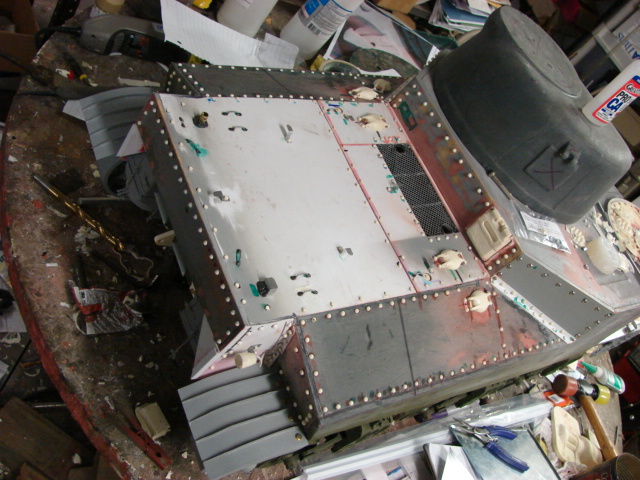
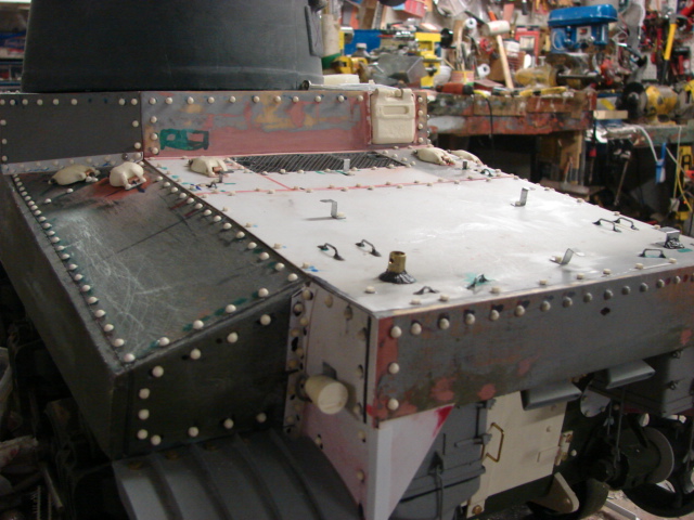
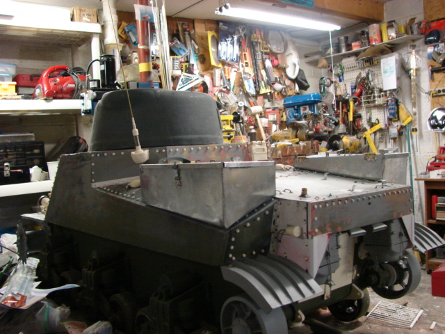
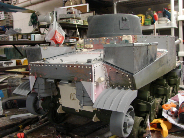
It has been a while since I had any updates, but I have made a lot more progress on the tank. The tank's rear deck is now complete.
I have also added a few more components to the product line.
http://www.eastcoastarmory.com/ustankparts.htm

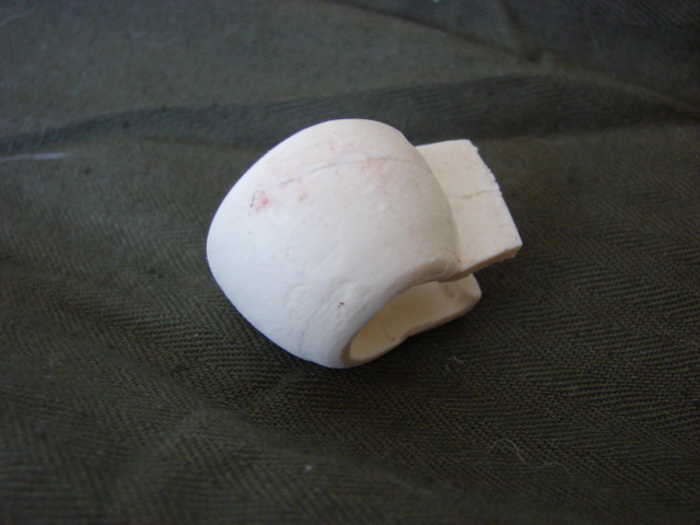
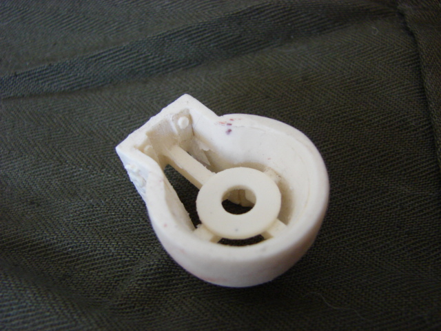
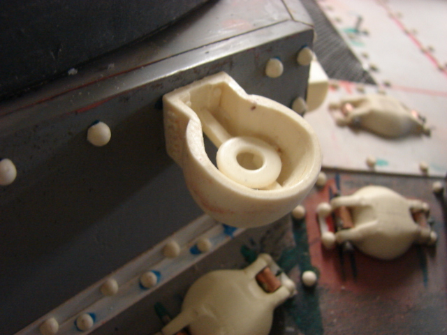
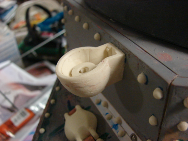
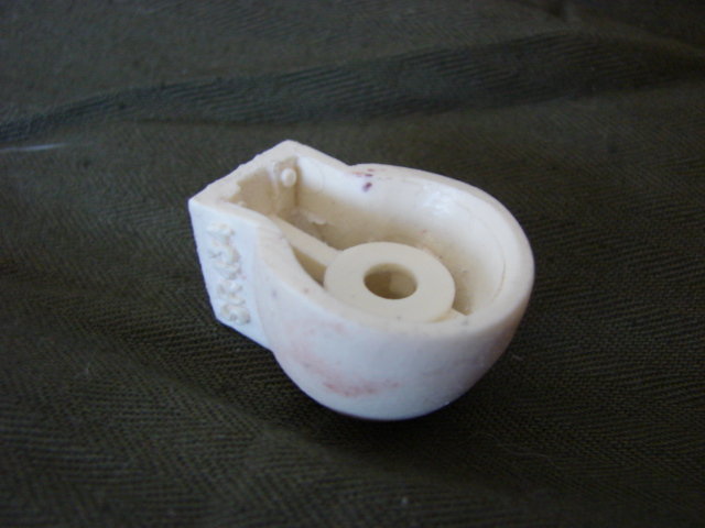
M3 Lee "Tea Cup" Antenna base mount.
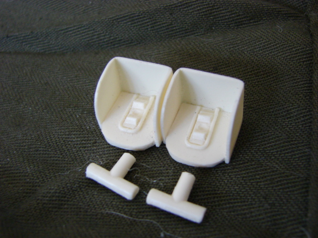
M3 Lee fire extinguisher cluster set
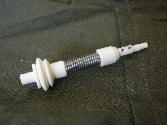
Retooled MP-37 spring antenna base
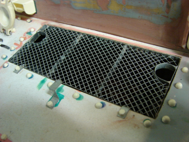
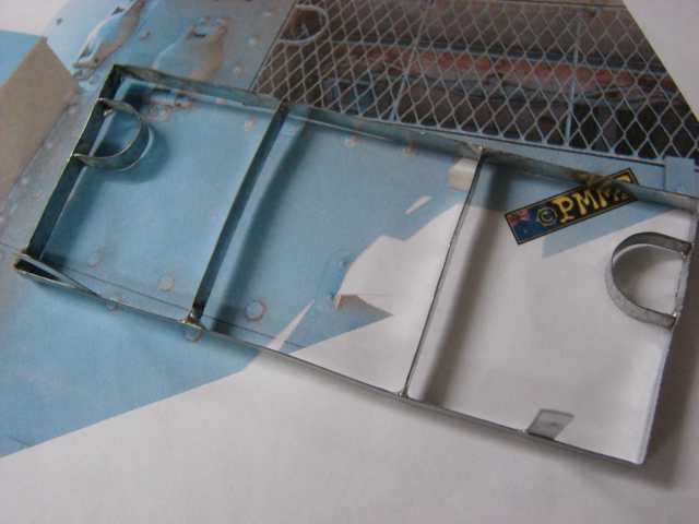
The tanks air intake was fabricated out of metal. The intake frame was constructed out of several pieces of sheet steel that was soldered together. Aluminum Varmint Mesh was then placed over the gill and installed.   
the gas cap cover were added, and are made to be functional. The gas caps them selves will be added after the tank is painted.
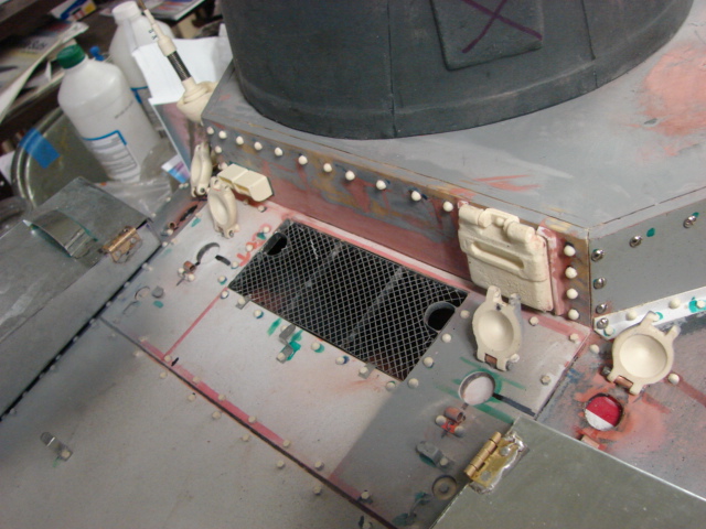
The rest of the rear deck details were added. These would include the tool posts, bolt details and riveting.
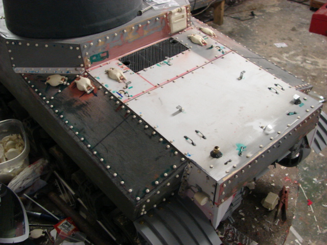
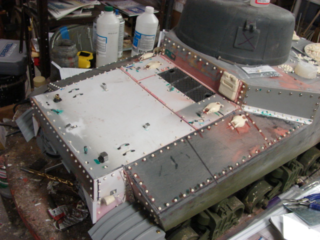
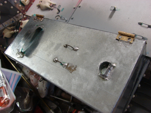
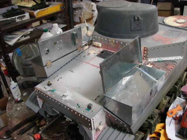
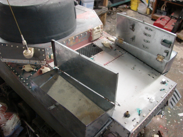
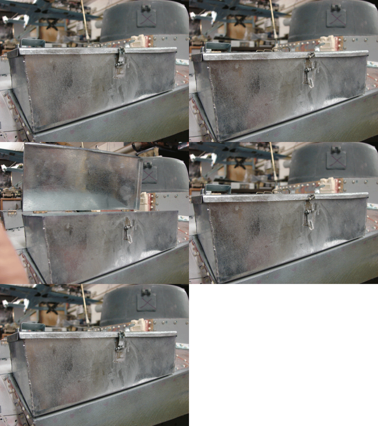
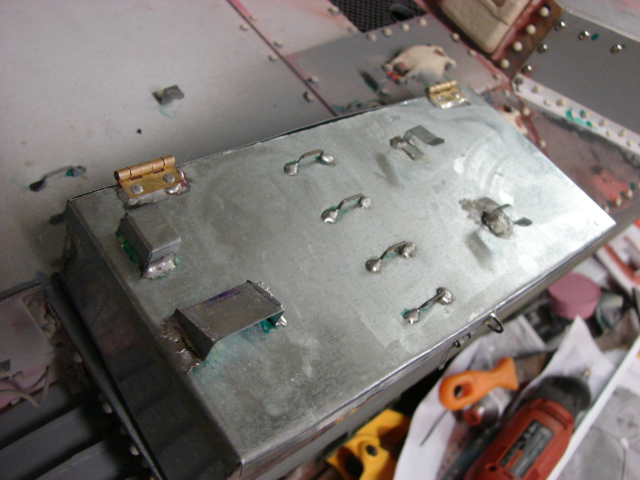
The tank's sheet metal storage boxes were constructed and installed. The boxes were soldered together, and are fully functional. They also have more tool posts added to their lids. These tool posts were also soldered directly onto the box lids.
The remaining details were added to the tank's upper rear plates. These would include the riveting, the visor, fire extinguisher, Antenna base mount, and rear visor.
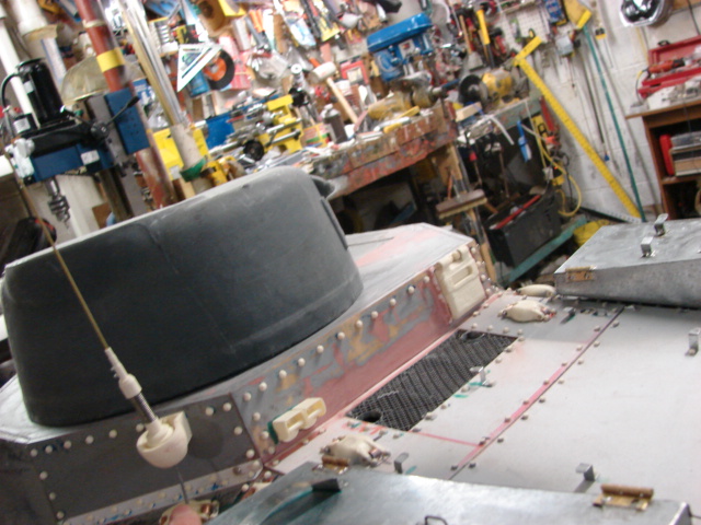
 

Due to the thickness of the plywood plate that was added to extend the rear, I decided not to make the rear visor functional. What I did was I purposely casted the hatch 1/2 way. This leaves the exterior detail to be casted crisply, without any of the interior detailing to be present. This way I don't have to sand off any of the intricate interior detailing of the hatch.
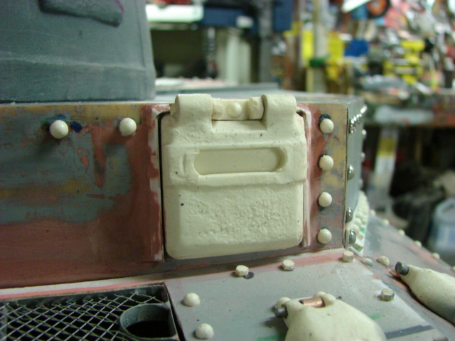
Like all US tanks, the M3 has an internal fire extinguisher system that can be triggered from the outside of the vehicle. On the M4 there is a small box which contains both handles, on the M3 each handle has it's own box, the two boxes are clustered together.
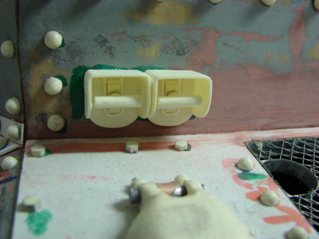
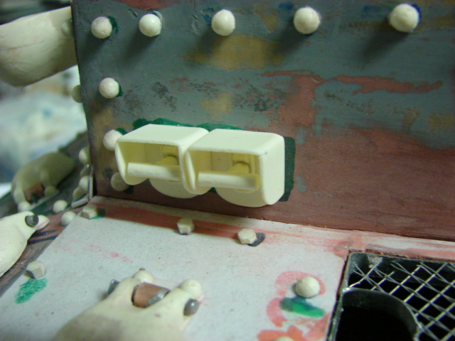
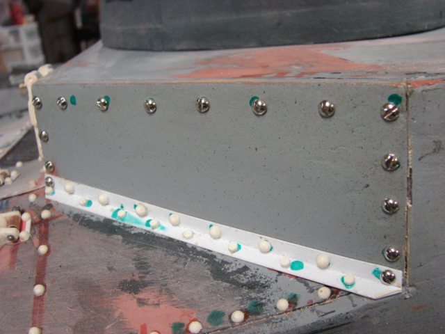
On the two corner plates, the details differ on each side. On the left hand side corner plate all of the fasteners used are rivets, except for one slot screw. The plate is also the spot for the"Tea Cup" antenna base mount. These antenna base mounts are only found on US Lees. Grants did not have this component because on the Grant the radio and antenna bases were moved to the turret.
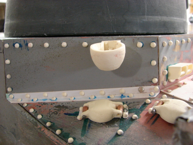
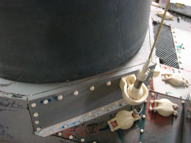
On the right hand side corner plate the plate uses large slot screws rather than the rivets, and on the lower portion of the plate where the plate meets the rear deck the plate in installed with hex bolts. The reason why this plate is designed to be removed is because it is to get access to the 75mm sponson gun. The gun is installed in the factory through this position, and can be removed in the field (not very practically) through this position.
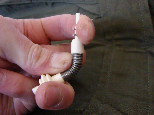
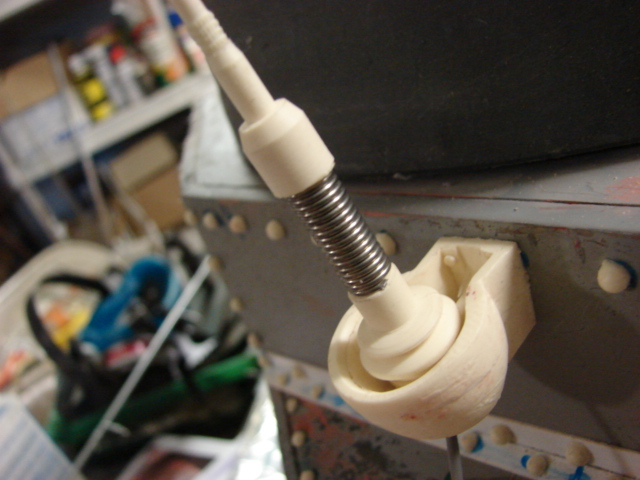
For this tank's antenna base I decided to use the earlier MP-37 aerial base, rather than the usual MP-48. The MP-48 antenna base can be used on the M3 as I have seen in many in action images.
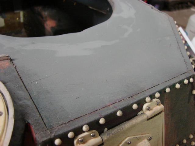
I have also started to proceed on the tank's roof. currently I completed the top roof body work, and I have etched the panel lines for the armored plates.
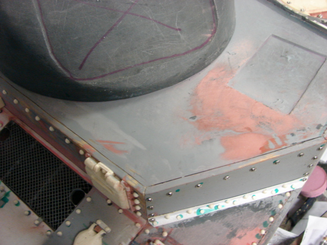
The side hatches will be my next area of focus. The side door hatch masters are almost ready and should be ready soon.

  • Member since
    April 2005
Posted by armourguy on Wednesday, December 9, 2009 3:34 PM

Thanks Guys, I have now completed the front portion of the M3.


I added two of these new details to the product line.


http://eastcoastarmory.com/ustankparts.htm


1. M3 Lee / Grant 75mm counter weight flange ring


2. Early US AFV headlight set. Set will work on most early war period US armored vehicles including the M3 Lee series, M3 Grant, M3 Stuart Series, and M6 Heavy tank. the headlights come hollow, with a clear vacuume formed lens.


Also as an update the Resin M3 Lee / Grant Front Visor set will also work on Canadian Rams, and Kangaroos.


http://web.inter.nl.net/users/spoelstra/g104/images/kangar03.jpg


The new parts were installed along with the remaining metal parts for the front fenders. These parts would include the brush guards, Pick axe head mounts, and the 30.cal tripod mount. All metal parts were soldered directly to the fenders.


30.cal tripod mounts are also mounted on the right hand side of the tank's front side plate. These mounts were fabricated out of sheet metal and are all soldered together.


Both 30.cal tippod mounts are functional, and will hold the tripods.


The wiring for the lights and the horn were added. The head light mounts have two wire posts, but from the Aberdeen vehicle, and all of the images that I have found only the one mount is used for the tank's wiring. On the Aberdeen tank the wire casing is rotted out exposing two separate insulated wires.If anyone knows about the other wire, or has pictures of the other wire please let me know.  


  • Member since
    April 2005
Posted by armourguy on Saturday, December 5, 2009 8:04 PM

I completed the sponson 75mm gun, and gun mount portion.

I decided to make the 75mm sponson gun transverse and elevate. To do this the molded in sponson rotor was removed. cast texture was also added to the front portion of the tank that housed the 75mm.

The new gun mount was made out of several pieces of PVC pipe, resin, and plywood. A 6" PVC pipe was used for the main rotor. An extension spring was added to prevent the weight of the main gun to droop.

The whole unit is installed on to the tank with one counter sunk screw that mounts to the tank's roof. The screw is connected with a few washers and a lock nut. This makes the gun rotate smoothly.

On the tank's roof there is a round plate that on the real tank mounts the gun mount rotor, to the tank, but also houses the 75mm gunner scope. The Kit supplies you with a resin detail disc. Overall the disc is the right size, and detail placement. I used the kit disc as a staring point for further enhancements.

When reworking the disc I removed the molded in outer ring, used the molded pilot holes for real slot screw placement, and replaced the center hub detail with a new disc. Casting marks and numbers were also added to the disc. the top roof area was reworked to house the new reworked resin disc. The disc also cover's up the counter sunk screw that hold the main gun rotor in place. The strip that is running along the disc will be mounted to the top deck support rails which will be fabricated later.

The disc overhangs off of the roof. This shelf was fabricated, and has a hollow rim towards the front. Several Cloth tarpaulin clips were added to the shelf and the sides of thesponson gun mount.

The M2 75mm gun barrel was machined out of PVC pipe, and was installed to the round mantlet.

Now that the gun has been installed I will now be working on the tank's headlights and horn. More info to come!

  • Member since
    April 2005
Posted by armourguy on Wednesday, November 25, 2009 10:58 PM

 RBaer wrote:
And here I thought 1/35 interiors were hard to see when the hull is together. I never in my whole life imagined putting filter elements inside the filter housings.....

Thanks, The air filters canister lids are removable via the wing nuts. so I can display the air filters.


It has been a while since I had an update, but I have been working on the tank and have made some progress

The front portion of the tank is now mostly completed. The transmission cover casting numbers were added, in addition to the rivets. For the left hand armored plate the bottom row of fasteners are not rivets, but are slot screws.

The tank's molded in bow 30.cal mount was deleted and new version was added in it's place. 

The front visors were built and added. The kit supplies you with these components casted in resin, but I wanted to make them functional so new versions created. For the front visor rim, I removed, and rewokred the bevel of the kit supplied resin armored visor. For the smaller visor I fabricated the rim out of 1/8th inch styrene square stock, which had a bevel added to it. 

More details (tool posts, head light mounts, and brush guards) will be added shortly.

I have added many of these new components to the product line. 

http://www.eastcoastarmory.com/ustankparts.htm

Resin M3 Lee / Grant Front Visor set. This set will also work on the M7 Priest.

Resin M3 Lee small visor Set

M3 Lee Bow 30 cal mount set.

M3 Lee / Grant Metal front fenders.

I will be working on the sponson 75mm gun portion of the tank next.


  • Member since
    September 2006
  • From: Dripping Springs, TX, USA
Posted by RBaer on Friday, November 13, 2009 2:34 PM
And here I thought 1/35 interiors were hard to see when the hull is together. I never in my whole life imagined putting filter elements inside the filter housings.....

Apprentice rivet counter.

  • Member since
    April 2005
Posted by armourguy on Thursday, November 12, 2009 9:56 PM

The last remaining detail parts have been added to the tank's rear hull. These would be the tail lights, the fenders, and the rear idler wheels.


The tank's air filters were also painted and placed inside the filter canisters

The new parts were added to the product line.
http://www.eastcoastarmory.com/ustankparts.htm

1. Metal M3 Lee "Claw" rear fenders.

2. M4 Sherman / M3 Lee Early spoke Idler Wheel Set.

The idlers were installed with the same method that I used on the Viper M4 Sherman. I use this method because the wheel is locked on to the tank, yet is still spins freely. 

  • Member since
    April 2005
Posted by armourguy on Saturday, November 7, 2009 11:50 PM

I have made some progress on the tank, I also added a few noew parts to the product line.
http://www.eastcoastarmory.com/ustankparts.htm

Resin M3 Lee / Early M4 Sherman lower hull tow shackle set. This set will work on M3 Lee's / Grants, M7 Priest, and the Viper M4 Sherman.

Resin M3 Lee / Early M4 Sherman rear hull engine hatch kit. This set will work on M3 Lee's / Grants, M7 Priest, and the Viper M4 Sherman.

For the tank's rear wall detailing I had a few different options to pick from. When the M3 Lee was first used the tank had two exhaust elbows that goose necked out of the tank's rear wall and extended out into two perforated "pepper pot" canisters.

The second M3 Lee exhaust layout was slightly different in arrangement. The "pepper pot" exhausts were replaced, In there place Air filter canisters were added, and replacing the goose necking exhausts a small dove tail exhaust was bolted onto the place where the first exhausts were in place.

The Third and final exhaust layout for the M3 series featured the same arrangement that is found on early M4 Shermans. This would be the air filters were retained, but the dove tail exhaust locations were moved to the center of the tank's rear. a round plate was bolted in the locations of where the first exhausts were origonaly placed.

The configuration that I decided to use on my model was the late version. I went with this route because I already have the air filter components and exhausts on hand. 

On the M3s that had the air filter upgrade steel plate was riveted onto the sides. This plate was for the air filter canister mounting, it also acted as a shield protecting the canisters from any debris that were kicked up by the tracks. These plates were also used on M4 Shermans that were equipped with the canisters. On the back portion of the tank two triangular plates were added. These plates cover up a portion of the air filter canister.

The riveting was also added. It is hard to tell from the pictures but there were two sizes of rivets that were used. The rivets that are on the portion that just out from the tank's rear upper hull are smaller than the rivets that are used for the other portions of the tank's armored hull plates. In addition to the riveting the tank's starter crank hole was added to the rear upper plate.

I will now be constructing the tanks early spoke rear idler wheels. More info is to come.

  • Member since
    April 2005
Posted by armourguy on Sunday, November 1, 2009 5:36 PM

Just a small update on the project, I have completed the tanks lower hull riveting, and details.

I also completed the installation of the tank's sprockets. For the sprockets I used a set of Plastic Panzer early ABS plastic drive sprockets. The sprockets are made out of CNCed ABS plastic and come with separate sprocket hubs and teeth rings. The sprocket hubs are pre drilled to place the included fasteners for the teeth rings. The sprockets are nicely shaped and detailed.

The back portion of the Plastic panzers sprockets is flush; because of this it will not have the proper spacing with the panzerwerk transmission final drive. A small modification needs to be made to make the Plastic Panzers sprockets fit the panzerwerks final drive hubs.
 

There are two ways to make the modification. One way would be to remove a 1/2 an inch off of the final drive. Another way to make the modification would be to machine the space into the sprocket. To do this mod you will need a machine lathe.

The sprocket's axel hole was enlarged to fit a 1/4 inch steel shaft.

The sprockets were installed with steel washers and spin freely, while being cradled by the final drives.

The next area of focus will be the tank's rear wall, and rear wall detailing.

  • Member since
    April 2005
Posted by armourguy on Tuesday, October 27, 2009 5:38 AM
 jetmodeler wrote:

Looking good so far. Are you also the one that built that 1/6 jagdpanther?

Hi Jetmodeler, The 1/6th scale jagdpanther was built by me. You can see my other 1/6th scale model builds on my website.  http://www.eastcoastarmory.com/battlezone.htm

  • Member since
    October 2009
  • From: South Carolina
Posted by jetmodeler on Monday, October 26, 2009 3:01 PM

Looking good so far. Are you also the one that built that 1/6 jagdpanther?


  • Member since
    January 2007
Posted by the doog on Sunday, October 25, 2009 6:41 PM

WOW, man; I give ya credit for some serious dedication to large-scale! Too big for me, but it's amazing the amount of work you're putting into this!

And the other models you've done--just fabulous, really! At least you don't have to worry about using magnifiers to do tiny parts! lol!

  • Member since
    April 2005
Posted by armourguy on Sunday, October 25, 2009 4:22 PM

I have made more progress on the tank.

I have completed most of the tank's lower hull detailing. About 25% of the lower hull riveting was added and the tank's armor plate lines were etched on to the tank's sponsons. The rest of the riveting will be added after the suspension is mounted.                                                     

The tank's working suspension and idler mounts were assembled and installed

Now that the suspension is complete I can finish the detailing of the lower and under hull.

JOIN OUR COMMUNITY!

Our community is FREE to join. To participate you must either login or register for an account.

SEARCH FORUMS
FREE NEWSLETTER
By signing up you may also receive reader surveys and occasional special offers. We do not sell, rent or trade our email lists. View our Privacy Policy.