SEARCH FINESCALE.COM

Enter keywords or a search phrase below:

Firefly construction question

2030 views
41 replies
1 rating 2 rating 3 rating 4 rating 5 rating
  • Member since
    January 2003
  • From: Utah - USA
Firefly construction question
Posted by wipw on Tuesday, May 11, 2004 2:09 PM
RE: Latest version of the DML Firefly Vc.

I'm at the point where I'm going to add parts to the top of the turret. On the commanders cupola ring, there is a cylinder at the front and the back. The one in the front is where the 50 cal mg mounts. The one in the back I can't figure out. It looks like a piece that looks like a sight of some sort mounts there, but it certainly won't fit in the cylinder. Does the cylinder need to be carved off or does the "sight" go somewhere else. The instructions for this kit really has some issues!

Thanks.
Bill ========================================================== DML M4A2 Red Army ========================================================== ========================================================== -- There is a fine line between "hobby" and "mental illness". (Author unknown)
  • Member since
    July 2003
  • From: Alberta, Canada
Posted by stukabomb88 on Tuesday, May 11, 2004 2:20 PM
My best suggestion would be to try looking it up on the net. You never know what kind of information can be found!
"If you live for personal gain, you have lived in vain." -Devon OpdenDries
  • Member since
    January 2003
Posted by shermanfreak on Tuesday, May 11, 2004 3:22 PM
Cut it off Bill. It's a small error that has ran through the DML line of Shermans.

Pick the one you want to keep.
Happy Modelling and God Bless Robert
  • Member since
    January 2003
  • From: Utah - USA
Posted by wipw on Tuesday, May 11, 2004 3:56 PM
Thanks a bunch. I knew I could count on a speedy answer out here, as always.

btw, I "solved" the problem of the back side of the idlers not being detailed by shaving down a set of extra Italeri idlers, cutting them in half, and gluing them into the rear of the DML wheels. Took a while to do it, but thanks to Mr Dremel, it wasn't too bad. I took some pictures of the steps, but my camera disappeared (again) at my wife's graduation. I've got her calling around to see if we can turn it up.

Oh, Robert; is that piece a sight, and does it glue down right where the cylinder in question is removed?

Thanks, again.
Bill ========================================================== DML M4A2 Red Army ========================================================== ========================================================== -- There is a fine line between "hobby" and "mental illness". (Author unknown)
  • Member since
    January 2003
Posted by shermanfreak on Tuesday, May 11, 2004 5:56 PM
The cylinder is the MG mount ..... the other little part B36 is the travel lock for the .50 barrel.
Happy Modelling and God Bless Robert
  • Member since
    July 2003
  • From: Philippines
Posted by Dwight Ta-ala on Tuesday, May 11, 2004 7:19 PM
Hey, thanks for posting this question, Bill. Gotta keep Sherm's reply on this as I have the same kit that I will be building soon. (Soon could mean in the within the next few years...he-he-he.)

  • Member since
    May 2003
  • From: Upstate NY
Posted by Build22 on Tuesday, May 11, 2004 9:32 PM


Bill,

One thing Sherm mentioned in another post was that the ring actually rotated so you can position your machine gun in any location aorund the hatch.


Jim [IMG]
  • Member since
    January 2003
  • From: Utah - USA
Posted by wipw on Wednesday, May 12, 2004 9:34 AM
Thanks, Jim. I wish I would have seen that one earlier. I have already glued the ring down.

Robert; Thanks so very much. I have done as you suggested.

Dwight; I cut the cylinder in the rear off. It left a bit of a hole under it, so I filled it with Squadron green and sanded it out.

I've got some pictures (found my camera!!!) and I'll post them below once I get them uploaded.
Bill ========================================================== DML M4A2 Red Army ========================================================== ========================================================== -- There is a fine line between "hobby" and "mental illness". (Author unknown)
  • Member since
    January 2003
  • From: Utah - USA
Posted by wipw on Wednesday, May 12, 2004 3:06 PM
Okay, here are the pictures I've taken of the turret ring. I'm also posting some pictures of what I did to the idlers in the Sherman Group Build.


These are the original DML idlers on the left., front and badk. As you can see, the back has no detail, in fact, it's completely hollow. Next is an Italeri (USMC Sherman) idler. They have detail (somewhat soft) on the front and back, but no center covers on the fronts, and big ejector pin marks on the back surfaces. Next are what was left after I turned down and split in half one of the Italeri Idlers.


Here they are with the Italeri centers inserted into the back of the DML idlers.


And one more time after painting.

I don't think they turned out too badly. Since they will be under the tank, they will probably pass all but a judges eye.
Bill ========================================================== DML M4A2 Red Army ========================================================== ========================================================== -- There is a fine line between "hobby" and "mental illness". (Author unknown)
  • Member since
    January 2003
Posted by shermanfreak on Wednesday, May 12, 2004 3:29 PM
Nice work on the idlers Bill .... a very effective solution.
Happy Modelling and God Bless Robert
  • Member since
    July 2003
  • From: Philippines
Posted by Dwight Ta-ala on Wednesday, May 12, 2004 6:33 PM
Hey, that's a cool tip, Bill. I'll take note of that, too. Thanks.

  • Member since
    January 2003
  • From: Utah - USA
Posted by wipw on Thursday, May 13, 2004 8:08 PM
Thanks, Guys. I put the PE part over the left headlight last night. Came out a little crooked. I'll have to see if I can straighten it out a bit.
Bill ========================================================== DML M4A2 Red Army ========================================================== ========================================================== -- There is a fine line between "hobby" and "mental illness". (Author unknown)
  • Member since
    January 2003
  • From: Utah - USA
Posted by wipw on Wednesday, May 19, 2004 1:07 PM
Dwight,

I hope you pick this up.

Here's another "fun" thing for you with this kit (also applies to the previous version DML made). In step 19, you have to fold up a little pe part (MA4) that gets glued onto the left side of the turret next to the square hatch on top of the turret. It shows to attach part B24 (a small, rectangular plastic piece) onto it. I hunted and hunted for B24 as it had been removed from my sprue. Then I noticed that in the same step, part B24 is shown as being the "inner mantlet", which it is! So then I spent a bunch more time hunting every sprue looking for the part. (I think it's supposed to be some sort of pad for the hatch to rest against.) I finally decided that the correct part number is B19. It looks right and there is no other reference to that part in the instructions.

Good luck with your model.

Robert;

Another question for you about uniform color. Thanks for the post in the other thread. What paints would you recommend for the kaki color of the uniforms?

Thanks, as always.
Bill ========================================================== DML M4A2 Red Army ========================================================== ========================================================== -- There is a fine line between "hobby" and "mental illness". (Author unknown)
  • Member since
    January 2003
Posted by shermanfreak on Wednesday, May 19, 2004 4:28 PM
QUOTE: Originally posted by wipw
I think it's supposed to be some sort of pad for the hatch to rest against.


Your assumption is correct Bill

QUOTE:
Another question for you about uniform color. Thanks for the post in the other thread. What paints would you recommend for the kaki color of the uniforms?

Thanks, as always.


I actually mixed my own for this one Bill using Artist Acrylics. I just kept mixing until I had something close.
Happy Modelling and God Bless Robert
  • Member since
    January 2003
  • From: Utah - USA
Posted by wipw on Wednesday, May 19, 2004 4:47 PM
Thanks, Robert. I brought in the instruction sheet and looked up the Gunze Sangyo colors and it lists an olive drab as the uniform color. Obviously, they got it all wrong! Sure glad we have you to fall back on!!Big Smile [:D]Big Smile [:D]Bow [bow]Big Smile [:D]Big Smile [:D]
Bill ========================================================== DML M4A2 Red Army ========================================================== ========================================================== -- There is a fine line between "hobby" and "mental illness". (Author unknown)
  • Member since
    July 2003
  • From: Philippines
Posted by Dwight Ta-ala on Wednesday, May 19, 2004 7:52 PM
Bil,:

Got it. Thanks. Hmmm. I can see myself building it now...in my mind.

Should look good in a 3-tone camo scheme.

  • Member since
    January 2003
  • From: Utah - USA
Posted by wipw on Thursday, May 20, 2004 11:31 AM
Think I'm getting close on this guy. I'm hoping to finish it this weekend. Then it's back to Elefants, and Tigers, and Panthers, OH MY!! lol
Bill ========================================================== DML M4A2 Red Army ========================================================== ========================================================== -- There is a fine line between "hobby" and "mental illness". (Author unknown)
  • Member since
    December 2003
  • From: Montreal
Posted by buff on Sunday, May 23, 2004 5:59 PM
I have another question about the DML Firefly Vc (kit # 6182). In step 4, you are supposed to remove a very thin bit that winds its way aroung what would have been (I think) the mount for the bow mg on Sherman variants that had one. Taking that off is going to make a heck of a mess. If I have to take it off, why did they put it there in the first place? And one more questions about tanks, generally. Should I paint the pioneer tools separately, or do I put them on then paint them the same colors as the vehicle itself? As always, thanks for the tips.

On the bench: 1/32 Spit IXc

  • Member since
    January 2003
  • From: Utah - USA
Posted by wipw on Sunday, May 23, 2004 6:08 PM
Hi, Bill.

Pioneer tools first. Some members paint the tools with them on, others with them off. I prefer to do it separately. If you do them while on the tank, one idea is to slip a piece of Post-it Note paper under the tool to keep the paint off the tank.

The ridge you are talking about. I sliced mine off without too much trouble, then I put liquid cement on the remnants of the molding, let the plastic get a little soft, then stippled it with a stiff brush to blend it in a bit. I was better, but still showed. However, you wind up putting an "armored cover" over the machine gun fitting (careful on placement, it doesn't look anything like it's supposed to in the instructions). After it was glued on and dried, I put a small bead of putty around the join line and pressed marks in it to look like a weld bead. It came out pretty well. Look at some of the molded in weld beads on the tank and you'll get an idea what it should look like.

Good luck. Hope this helps.
Bill ========================================================== DML M4A2 Red Army ========================================================== ========================================================== -- There is a fine line between "hobby" and "mental illness". (Author unknown)
  • Member since
    December 2003
  • From: Montreal
Posted by buff on Sunday, May 23, 2004 8:12 PM
Bill,
Indeed it does. I'll give it a try. Thanks.

On the bench: 1/32 Spit IXc

  • Member since
    December 2003
  • From: Montreal
Posted by buff on Thursday, May 27, 2004 4:07 PM
I have a few more questions concerning this kit.
First, the fit of part A-9, the back deck of the tank. Mine does not fit flush with the rest of the upper hull. It is 1mm below on both of the sides along the length of the vehicle. Is that right, or should I be looking to make it flush?
Second, the weld on the top of A-27, the plate at the back of the upper hull. I assume that since the plate was welded on to the rest of the hull, there should also be a weld seam on the back of the upper hull, other wise it looks as though it wasn't welded on to anything. I have a gap between the A-27 and the upper hull that I need to fill with putty, so should I make a weld seam in the putty to make it look like the two pieces were welded together?
Third, the fit of that same part A-27 with the upper hull. Along the bottom edge of the upper hull there are raised ridges that runs the length of the vehicle along both sides. They are supposed to match identical ridges on A-27, and they do. But just above where those ridges meet, there is a 1/4 inch of vertical hull where the fit is not flush. Those vertical bits of the upper hull stick out about 1mm past the edge of A-27 on both sides. It is very visible, and it doesn't look right. Should those corners of the vehicle be flush?
Finally (thanks for your patience), about those ridges on either side of the hull. They have a series of little bumps along them. Are they rivets or bolt heads or something else? There is a line that connects them together. It looks like a parting line? Is it?
Sorry for all the questions at once but I determined to make this kit to look right. Thanks.

On the bench: 1/32 Spit IXc

  • Member since
    January 2003
  • From: Utah - USA
Posted by wipw on Thursday, May 27, 2004 4:42 PM
Bill, no problem. I'm at work and don't have either my Firefly or the instructions here with me, so I'm not going to be able to be much help until I can go over your questions at home. Sorry. I had a lot of trouble with the back of my Firefly. One big problem I had is that I have a copy of the Firefly release just prior to the newest one and was stupid enough to have both open at the same time to compare the parts. And, you got it, I mixed the parts between up between the kits! Gave me major problems, I can tell you. I'm still not sure I got them all right.

Anyway, the one thing I do know about sitting here is the question you had about the ridges on the hull side. the bumps are supposed to be there, I think they represent bolt heads, but the seam that runs between them is, as you said, a parting line. Stupid place for the, I think, but maybe they couldn't put it anywhere else. It scrapes down pretty easily. What I had a bit of trouble with was the sprue attachment points, which they put on those ridges. There are three things that I find fault with on DMLs kits; first are their instructions. They usually leave you guessing on placement of a number of parts, and many have errors on them (like part B24 that I mentioned above). Next is that they have some huge ejector pin marks in bad places, like their track links. And finally, their sprue attachment points are huge, too. Tamiya and Hasagewa (wingy thingies, at least) have much smaller, less obtrusive attachment points.

Well, enough rambling on. One of my sons has a baseball game then pack meeting tonight. I'll try to remember to get those things out after that and get back to you. It may be tomorrow, though.

Have a good evening.
Bill ========================================================== DML M4A2 Red Army ========================================================== ========================================================== -- There is a fine line between "hobby" and "mental illness". (Author unknown)
  • Member since
    January 2003
Posted by shermanfreak on Thursday, May 27, 2004 6:00 PM
I'll wade in here for a couple of answers
Yes A-9 should be flush with the upper hull, I just test fit mine and it appears a little low but not enough to make me shim it.
A weld seem would be fine between the rear plate and the back of the upper hull. There was one there on the real one.
Yes the "plate" that runs the length of the tank should align with the ones on the rear plate.
And in regards to the bolts, rivets or what ever they are supposed to be. The "ridge" that runs the length of the tank was an attachment point for the sand shields. Without the shields in place, which aren't included in the kit, each of these little bumps should actually be holes. Happy drilling !!!!!
Happy Modelling and God Bless Robert
  • Member since
    January 2003
  • From: Utah - USA
Posted by wipw on Thursday, May 27, 2004 6:14 PM
Bow [bow]Bow [bow]Bow [bow]
Bill ========================================================== DML M4A2 Red Army ========================================================== ========================================================== -- There is a fine line between "hobby" and "mental illness". (Author unknown)
  • Member since
    December 2003
  • From: Montreal
Posted by buff on Friday, May 28, 2004 7:18 AM
QUOTE: There are three things that I find fault with on DMLs kits; first are their instructions. They usually leave you guessing on placement of a number of parts, and many have errors on them (like part B24 that I mentioned above). Next is that they have some huge ejector pin marks in bad places, like their track links. And finally, their sprue attachment points are huge, too.

I have found exactly the same problems. They also stick those little plastic knobs on most of the parts, too. That's just more stuff to scrape off. I took a look at the tracks last night, and it seems like every track has ejector pin marks on it. It is all very annoying.
QUOTE: Without the shields in place, which aren't included in the kit, each of these little bumps should actually be holes. Happy drilling !!!!!

D'Oh!!
Robert, what do you recommend for drilling those holes? And I heartily second Bill's last. Your knowledge of the Sherman is awesome. Thanks for all the help.
Bill

On the bench: 1/32 Spit IXc

  • Member since
    January 2003
  • From: Utah - USA
Posted by wipw on Friday, May 28, 2004 10:26 AM
Good morning, Bill.

Last nights schedule changed a bit and I was not home until after 9:00. I didn't get anything I had planned done. Except, I did look at my Firefly and the instructions. Believe it or not, I didn't have much of any fit problems with either A27 or A9! Go figure. It seems to me I had to push and prod the rear hull sides to match up with A27, but it worked out okay. I do see what you're talking about on the weld seam on that part, but as I didn't have to use any putty there, I left it as it straight from the box. My rear deck fits close to perfectly, if a little tight. Actually, I have a very small gap at the front of the plate, right behind the turret. With the turret in place, I don't think it will be able to be seen.

The little plastic knobs you were talking about are, I believe, areas where "excess" plastic can flow during molding. That way they can be sure the plastic didn't leave any voids. Also, I think they are yet more ejector pin areas. So maybe they have a double purpose.

I was going to glue the box on the front of the hull in step 10, but could not make it fit so that it looked right. So, I glued it on the rear hull as per step 11.

One place I had a major fit problem, at least it looks like it, but maybe it's right, was step 19. When I glued the B12 box assembly onto the rear of the turret, I wound up with a pretty sizable gap between the top of the box and the turret. Maybe I glued it too high up on the turret. I don't know, but it sure looks weird.

Also, be careful gluing B18 to to turret in step 16. It looks, to me, like it goes right next to the square hatch (B21). If you look at step 19, it shows where I think it goes a little clearer. Both drawings show that there are locator marks on the turret for them. Mine certainly didn't have any!

Hope you're having fun with it. It still was a lot of fun to build, even with all these little challenges. (But I'm about ready to get some Friul tracks for it, if I can find any!)
Bill ========================================================== DML M4A2 Red Army ========================================================== ========================================================== -- There is a fine line between "hobby" and "mental illness". (Author unknown)
  • Member since
    November 2005
Posted by Anonymous on Friday, May 28, 2004 10:59 AM
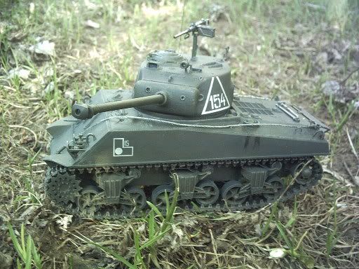
Cant believe I missed this tread. Bill if you find fruil tracks for it let me know where I have the same kit with the same problems and their indie's are gonna need some tlc that I dont have, I didhovever by pass alot of the turret/ cuploa issuies by getting a resin one with tools as well.injector marks on front of the tools......what was dml thinking, they are on my jagdtiger's tools as well. Anyway here is a pic of the turret


and how is this suppose to look cause this isnt right the trans cover thingies sorry dont know the correct word for em

  • Member since
    January 2003
  • From: Utah - USA
Posted by wipw on Friday, May 28, 2004 11:12 AM
Hey, Ron. What part of Omaha do you live in? When I was stationed at Offutt, I lived in LaVista!!

Your build looks pretty good to me. Where did you get the turret, and what manufacturer is it? Looks nice. I'm thinking very strongly of getting the Formations full set and doing another one! One thing I noticed, and this isn't in the instructions, the slots on the side of the hull have pieces that go in them before you put the boggies on. I can't remember the part number, but they are the squarish things on the V sprues. They are right above the return rollers.

One other thing I noticed about this kit. The pe parts are nickle silver, or something. They are very stiff comparted to brass, and a little thicker, I think. I annealed mine over a candle flame and they were still stiff to bend. They look pretty good when done, just a little more force involved in the bending.
Bill ========================================================== DML M4A2 Red Army ========================================================== ========================================================== -- There is a fine line between "hobby" and "mental illness". (Author unknown)
  • Member since
    December 2003
  • From: Montreal
Posted by buff on Friday, May 28, 2004 11:22 AM
QUOTE: One thing I noticed, and this isn't in the instructions, the slots on the side of the hull have pieces that go in them before you put the boggies on

Bill, you are not referring to the small rectangular pieces that go on the underside, are you?
Bill

On the bench: 1/32 Spit IXc

  • Member since
    January 2003
  • From: Utah - USA
Posted by wipw on Friday, May 28, 2004 11:29 AM
Nope, those are only about 3x5 mm and located above the return springs on the sprue, I believe. The ones I'm talking about go on the side of the hull in the slots. They butt up against the ones I think your talking about and are about 1x1 cm. (Understand, I am back at work and my tank is at home. These sizes are total estimates as best I can remember. I'll see if I can get some pics up of these places I'm talking about.
Bill ========================================================== DML M4A2 Red Army ========================================================== ========================================================== -- There is a fine line between "hobby" and "mental illness". (Author unknown)
JOIN OUR COMMUNITY!

Our community is FREE to join. To participate you must either login or register for an account.

SEARCH FORUMS
FREE NEWSLETTER
By signing up you may also receive reader surveys and occasional special offers. We do not sell, rent or trade our email lists. View our Privacy Policy.