SEARCH FINESCALE.COM

Enter keywords or a search phrase below:

Firefly construction question

2014 views
41 replies
1 rating 2 rating 3 rating 4 rating 5 rating
  • Member since
    November 2005
Posted by Anonymous on Friday, May 28, 2004 11:49 AM
Its a from chesapeake model designs and came with the kit as a trade for wingythingies . The PE's on this kit wernt too bad the jagdtigers was like thrimming 1/2 inch steel with a hedge trimmers, I will look into the hull part they seem to fit ok And I live in Millard so not to far from Lavisita small world
  • Member since
    January 2003
  • From: Utah - USA
Posted by wipw on Friday, May 28, 2004 11:51 AM
Ron, I'll see if I can get a picture of what I'm talking about and post them at lunch. (Don't hold your breath!!)
Bill ========================================================== DML M4A2 Red Army ========================================================== ========================================================== -- There is a fine line between "hobby" and "mental illness". (Author unknown)
  • Member since
    January 2003
  • From: Utah - USA
Posted by wipw on Friday, May 28, 2004 4:49 PM
Okay, here they are. I'm posting 6 pictures I took at lunch. I hope they help with you questions. Sorry, they are a little dark.
btw; I LOVE this Humbrol Bronze Green! Color on my monitor is pretty close to the model, if a little dark.


I took this to show what I did with the "welded" cover over the mg mount and where the bead around the mg mount was removed. I could have done better blending it in.


A shot from above. Main purpose here was to show how the stowage boxes fit on the back of the turret.


As you can see from this pic, on mine, the engine deck lined up pretty well with the top of the hull sides. Guess I got lucky on one thing!! lol


This one just shows how the rear plate fit against the hull sides. How do you like the mars across that paint job?? It's what I get for trying to push the deck forward. Note the engine deck isn't glued in. It's a very tight fit. Except for...


Here's the gap between the engine deck and the rear of the turret area. Not sure how I'm going to fix this one, yet.


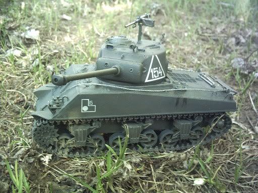
And finally, here are the boggies. I tried to get a picture of the plate that goes behind them, but it didn't work out too well. I'll try again tonight with a flash and see if it brings them out better. But you can see the edge of the plate, if you look closely.

Have fun. Post some pics of yours, if you can. Mission Models is out of Friulmodel ATL-12's. Which are, I believe, correct for this one. At least they are T-54-1s. The kit ones are a real pain. But I'm still trying, Robert!!
Bill ========================================================== DML M4A2 Red Army ========================================================== ========================================================== -- There is a fine line between "hobby" and "mental illness". (Author unknown)
  • Member since
    January 2003
Posted by shermanfreak on Friday, May 28, 2004 5:46 PM
Looking good Bill & Ron.

Ron - The C.M.D. Firefly turret is very nicely done isn't it. I've had a few of their products through the years and I highly recommend them. Gotta luv those DML tracks. Mischief [:-,]

Buff Bill - a pin vice is the easiest way to drill those out. If you don't have one, check out Princess Auto (if you have one in your area), if not, go to a welding supply store and get a tip drill. They usually come with 10 - 15 drill bits.
Happy Modelling and God Bless Robert
  • Member since
    January 2003
  • From: Utah - USA
Posted by wipw on Friday, May 28, 2004 5:49 PM
Robert, what size drill is correct, and how deep should the holes be? Just through the bracket, or all the way through the fender? Thanks, yet again!!
Bill ========================================================== DML M4A2 Red Army ========================================================== ========================================================== -- There is a fine line between "hobby" and "mental illness". (Author unknown)
  • Member since
    January 2003
Posted by shermanfreak on Friday, May 28, 2004 6:10 PM
QUOTE: Originally posted by wipw

Robert, what size drill is correct, and how deep should the holes be? Just through the bracket, or all the way through the fender? Thanks, yet again!!


Not being a rivet counter ...... pick a drill, any drill !!!!Tongue [:P]
I usually just pick one that looks close and drill them all the way through.
In reality, the bracket overhangs the hull a little bit but most kits are molded with it flush to the bottom of the hull.

Gee ..... you guys got your own little group build happening here. Approve [^]

Happy Modelling and God Bless Robert
  • Member since
    January 2003
  • From: Utah - USA
Posted by wipw on Friday, May 28, 2004 6:15 PM


LOL!! Funny, I was thinking about the same thing when I posted the pics. It should be called the I'm still not done with this Firefly for the group build, group build!!
Bill ========================================================== DML M4A2 Red Army ========================================================== ========================================================== -- There is a fine line between "hobby" and "mental illness". (Author unknown)
  • Member since
    November 2005
Posted by Anonymous on Friday, May 28, 2004 6:47 PM
Indeed they are Rob , the problem I think I have is with the bolt thingies that are in front of the transmission cover,on the bottom they seem to just stop and they kinda lift up at the end , not flush with the rest, and I tell ya something I used Mr. surfacer to get the cast texture on the trans cover and it came out wonderful. Oh ya Bill in my instructions it shows the square peices I beleive you are talkin about , the kit I have is# 6121 the sherm that knocked whittmann to the moon, and yours looks great is that the sharpie method I see on the road wheels?
  • Member since
    December 2003
  • From: Montreal
Posted by buff on Saturday, May 29, 2004 6:59 AM
Bill, thanks for the tips and the pics. I have the same gap on my back deck too. Because that part of the deck is notched, there is no way to avoid having a gap. I figured that meant it was supposed to be there, though why was a bit of a mystery.
Shermanfreak, thanks for the tip on the tools.

On the bench: 1/32 Spit IXc

  • Member since
    January 2003
  • From: Utah - USA
Posted by wipw on Saturday, May 29, 2004 2:30 PM
Ron, Yep, I Sharpied them, but I haven't flat coated them yet. What step in the instructions are those square jobs shown??
Bill ========================================================== DML M4A2 Red Army ========================================================== ========================================================== -- There is a fine line between "hobby" and "mental illness". (Author unknown)
  • Member since
    November 2005
Posted by Anonymous on Saturday, May 29, 2004 7:22 PM
Step2 part # C28
  • Member since
    December 2003
  • From: Montreal
Posted by buff on Monday, May 31, 2004 7:06 AM
In my kit, those parts are V-5. There is no mention of them anywhere. My instructions show the running gear attaching directly to the lower hull. That is incredibly poor on Dragon's part. Don't they have anybody proofreading their instructions?

On the bench: 1/32 Spit IXc

JOIN OUR COMMUNITY!

Our community is FREE to join. To participate you must either login or register for an account.

SEARCH FORUMS
FREE NEWSLETTER
By signing up you may also receive reader surveys and occasional special offers. We do not sell, rent or trade our email lists. View our Privacy Policy.