SEARCH FINESCALE.COM

Enter keywords or a search phrase below:

1/72 TIE Defender buildup

8703 views
40 replies
1 rating 2 rating 3 rating 4 rating 5 rating
  • Member since
    March 2007
  • From: Atlanta, Ga.
Posted by MrSquid2U on Tuesday, October 6, 2009 5:37 PM

After too long a delay, much spent accumulating parts and then even redoing one false start because I didn't like my own layout, I have started the board for the electronic components which control the various functions.


  • Member since
    August 2009
Posted by darkwolf29a on Wednesday, September 30, 2009 2:26 PM
Ok...That was a duh moment for me as well. :) As soon as you said the sandpaper was sitting there....I noticed the surrounding area was covered in the stuff. LMAO Don't mind me...I'm just clueless sometimes.
  • Member since
    March 2007
  • From: Atlanta, Ga.
Posted by MrSquid2U on Saturday, September 26, 2009 5:14 PM

DOH!

Darkwolf! I think I finally realized what your referring to! I set the base upon SANDPAPER to take the picture and you're looking through the area where the rear flat panel will occupy!

That will become a backlit transparency of the ship schematic later on! I'm so very sorry for stumbling through this explanation so long now.Sign - Oops [#oops] 


  • Member since
    March 2007
  • From: Atlanta, Ga.
Posted by MrSquid2U on Saturday, September 26, 2009 4:41 PM
 darkwolf29a wrote:

It looks like the tape above to me, on the inside of your base. If it isn't that type of tape, how did you create that effect?

It's coming right along, and looking great.


Oh. No, just "paint"? It's a 50/50 gloss/flat black, or "satin black" of course. Then there's a topcoat of a House of Kolor 'Phase Shift' paint that turns Green/Blue/Gold depending on light angles which probably gives it the shimmer you thought of with that nonslip kind of tape. And thank you very much!


Here's the base colors applied with a quick mockup and then a light test.


  • Member since
    August 2009
Posted by darkwolf29a on Wednesday, September 23, 2009 11:11 AM

It looks like the tape above to me, on the inside of your base. If it isn't that type of tape, how did you create that effect?

It's coming right along, and looking great.

  • Member since
    March 2007
  • From: Atlanta, Ga.
Posted by MrSquid2U on Friday, September 18, 2009 3:37 AM

Wolfie,

 Sorry for the delay. I'm not sure where you mean? But I can say that tape won't be part of the finished product.  Thanks.


The location of the guns out on the wingtips originally caused me to go with fiber optics but after breaking one here and there during handling I rethought that decision.

Rebuilt every gun so that an LED would become part of the gun itself. 


With wiring being bulkier than fiber I also had to reroute connectivity. 


But eventually even without light block applied it far outshines what fiber could transfer.


And there are four in blue and four in green.


  • Member since
    August 2009
Posted by darkwolf29a on Monday, September 14, 2009 10:29 AM
Very nice looking base. Did you use actual grip tape on there, or how did you do that inner portion of the base. It appears like grip tape to me.
  • Member since
    March 2007
  • From: Atlanta, Ga.
Posted by MrSquid2U on Thursday, September 10, 2009 5:55 PM

CPD, Batman,

 Thanks for the kind words. They're much appreciated. 


The base has it's basic colors on now and after this come the topcoats.


  • Member since
    September 2009
  • From: Garland , Tx
Posted by batmancustoms on Thursday, September 10, 2009 12:32 AM
Just to dang awesome!
John 'Panzer' Hinton http://www.batmancustoms.com/
  • Member since
    February 2008
Posted by CPD730 on Wednesday, September 9, 2009 8:53 PM
Just read the thread, very well done!! I also look forward to seeing the finished piece.  I think the stand your making will add the extra flair your looking for to an already outstanding piece.  Keep up the good work (and man you get some modelling time in your schedule!!)
"I was quit when I came in here, I'm twice as quit now." Deckard
  • Member since
    March 2007
  • From: Atlanta, Ga.
Posted by MrSquid2U on Wednesday, September 9, 2009 2:40 PM
While originally thinking of "hidden hinges" I eventually went against that because to make room for their "swing" inside would require some ugly pockets to be cut into the framing and traditional hinges would assure that the doors would open and then lay flat against the next panels to them. So fashioned up some hinges from brass tubing and strip which was then sunk flush into their mounting areas. The overlength wires for hinge pins are just place keepers for mock up.


  • Member since
    March 2007
  • From: Atlanta, Ga.
Posted by MrSquid2U on Tuesday, September 8, 2009 1:39 PM

DarkWolf,

 You've flattered me but don't ever limit yourself. It's usually just a matter of sticking to it until it starts to look like what you envisioned.Wink [;)]

Griff,

 Well, since you are often a judge yourself- I hoped to offer something that would somehow "add" to the model ? Maybe help it sit upon a display table just a bit better than otherwise? And of course it should be fun to play with too.Tongue [:P]


And thank you kindly gents for the generous words.Cool [8D]


  • Member since
    June 2004
  • From: The House of Blues Clues
Posted by Griffworks on Tuesday, September 8, 2009 12:56 PM

Lookin' awesome!  Love how that base looks, as well, Don.


The greatest measure of a man is his children and what kind of people they are.


  • Member since
    August 2009
Posted by darkwolf29a on Tuesday, September 8, 2009 10:39 AM

Looking very good, Squid-man!!!!

 I must admit, I'm a bit envious, at the moment. The base itself looks fantastic. I can only imagine what the overall look will be, once you're done. And...I can only wish to reach half of your skills, sir.

  • Member since
    March 2007
  • From: Atlanta, Ga.
Posted by MrSquid2U on Tuesday, September 8, 2009 4:39 AM
And this will be the area for control switches to the eight guns, cockpit lighting, thruster engines and also the base will house a light shone up towards the model itself.


  • Member since
    March 2007
  • From: Atlanta, Ga.
Posted by MrSquid2U on Monday, September 7, 2009 11:59 PM

Wanted a base that would pull styling cues from the subject so chose an octagon (like the cockpit glass) with panels that have framing like the wings and then atop a lil spoked hub like a pylon to wing mount.

And left two panels to be hinged which will open to expose the actual controls.


  • Member since
    March 2007
  • From: Atlanta, Ga.
Posted by MrSquid2U on Friday, September 4, 2009 6:35 AM
Jumping back to the hatch started to rough up a hinge mechanism. Chose square brass stock with requisite holes drilled in (78 drill bit) which was bent and filed down to shape and thickness to mimic some molded in details of the kit which were removed. Went with all brass components because while styrene definately works and is easier it can also fail at some point down the road and just cause you to regret the choice!;)


  • Member since
    March 2007
  • From: Atlanta, Ga.
Posted by MrSquid2U on Thursday, September 3, 2009 6:31 PM

"Hollowed out" the solid clear cast canaopy and it looks like with a coat of Future it should work out.


  • Member since
    March 2007
  • From: Atlanta, Ga.
Posted by MrSquid2U on Tuesday, September 1, 2009 8:46 PM
Before moving ahead I went back to readress the wing to pylon mounts. When I drilled them out to run the FO I lost alot of what was meant to be the contact area for glueing them together and now since I do have FO inside the last thing I want is a wing to snap off later on and take out the rather delicate Fiber.
 So I fashioned up collar and sleeves which are each well affixed in place and then these will be much sturdier together than what I had.


  • Member since
    March 2007
  • From: Atlanta, Ga.
Posted by MrSquid2U on Monday, August 31, 2009 6:47 PM

Worked on the top hatch that I had freed from the "ball" to fabricate a 'lip and seal' which should look better and also help to 'light block' since the interior will be lit. Fashioned everything up with styrene strip and some half round then worked it down to the final sizes I wanted. In the end it sits just about no more "above" the surface than originally but should be nicer than just plopping the cut apart pieces back together with a hinge.


  • Member since
    March 2007
  • From: Atlanta, Ga.
Posted by MrSquid2U on Monday, August 31, 2009 3:20 PM
 TD4438 wrote:

Here ya go.

/forums/1054473/ShowPost.aspx


I posted on that thread asking if I could join this late?

Thanks again!


  • Member since
    March 2006
Posted by TD4438 on Monday, August 31, 2009 2:28 AM

  • Member since
    March 2007
  • From: Atlanta, Ga.
Posted by MrSquid2U on Monday, August 31, 2009 2:19 AM

 TD4438 wrote:
Personally,I can't wait to see this one finished.Are you gonna include it in the Star Wars group build?


Um, I guess I wasn't aware of a GB for SW?

That might be fun though so thanks I'll look into it.Thumbs Up [tup]


  • Member since
    March 2006
Posted by TD4438 on Monday, August 31, 2009 1:52 AM
Personally,I can't wait to see this one finished.Are you gonna include it in the Star Wars group build?

  • Member since
    March 2007
  • From: Atlanta, Ga.
Posted by MrSquid2U on Monday, August 31, 2009 1:33 AM

Decided to go ahead and give it a working hatch as well as the lil windows within it.


  • Member since
    March 2007
  • From: Atlanta, Ga.
Posted by MrSquid2U on Sunday, August 30, 2009 7:17 AM

The only thing/s glued to stage this shot was the wing/s to pylon/s. The FiberOptic from each was routed down through the tube to an eventual stand for the controls. But otherwise all the components were 'pressed' into place as described earlier. But I couldn't resist putting this into place to get an idea of what it will look like and IMHO this one sharp, sleek and menacing lil ship!


 I can't wait to move forward to see it get into paint!


  • Member since
    March 2007
  • From: Atlanta, Ga.
Posted by MrSquid2U on Sunday, August 30, 2009 4:21 AM

 With the "ball" mounting sorted out it was time to address what goes on the other side of the "pylon hub", call it the backplate if you will, with those three thrusters.
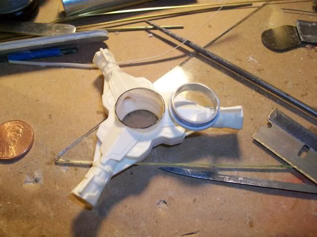
 Since I have an unfounded phobia about buttoning up electronics and not being able to reach them later I wanted something to simplify getting to those three LEDs I'd already sunk into place. Putting the common ground electrodes arranged to the 'outside' just happened to match up near the diameter of where it needs to mount to the pylon. So, using an old trick that I like, I simply put two "slip fit" pieces of brass tubing, cut with lil clearance grooves that when snapped together trap those electrodes. The two sandwhiched rings are now held in place by the electrodes themselves (which will only take one common ground wire soldered to the brass ring) and this in turn slips within another aluminum tube ring that is within the pylon hub. In this way wiring is simplified, mounting is accomplished and access is assured if needed.


  • Member since
    March 2007
  • From: Atlanta, Ga.
Posted by MrSquid2U on Saturday, August 29, 2009 10:53 PM

A couple of things presented themselves after maikng my two halves whole.

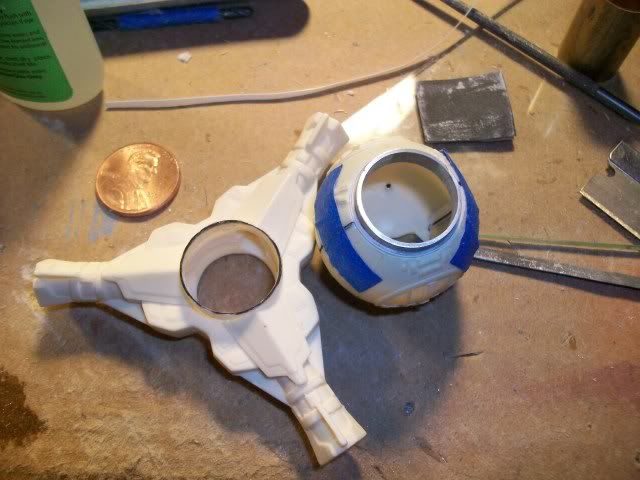
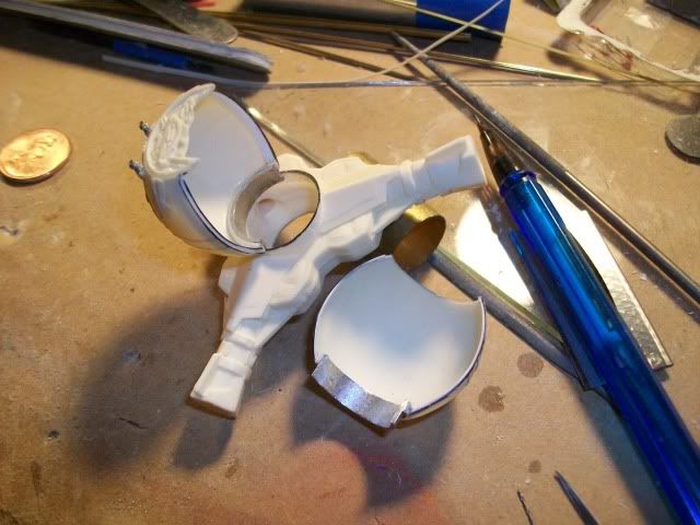
One is the natural tendency of something pliable to resist maintaining it's shape when holes are cut into either end, like the ball does have. The other was how to mount my two pieces onto the engine pylon while still allowing easy disassembly?

 One answer, was to fabricate a "collar" that fit into the sphere halves and then the pylon mount. Did so with alumium and styrene (again!) and now it not only holds it's shape but will go in, or come apart as needed.


  • Member since
    March 2007
  • From: Atlanta, Ga.
Posted by MrSquid2U on Saturday, August 29, 2009 6:39 PM
Looking forward to the time of assembling this kit I realized that my "cockpit/ball" is sitting in two pieces? Hmmm, that won't do? I like to leave things "serviceable" when electronics are involved so I first made sure that the adjoining edges of each half sphere were uniform to less than .015" and then made up a lip on one and a receiving 'groove/trench' on the other, out of .015 styrene.


JOIN OUR COMMUNITY!

Our community is FREE to join. To participate you must either login or register for an account.

SEARCH FORUMS
FREE NEWSLETTER
By signing up you may also receive reader surveys and occasional special offers. We do not sell, rent or trade our email lists. View our Privacy Policy.