SEARCH FINESCALE.COM

Enter keywords or a search phrase below:

Japanese Oil Tanker *update 7-12*

16015 views
67 replies
1 rating 2 rating 3 rating 4 rating 5 rating
  • Member since
    March 2005
  • From: West Virginia, USA
Posted by mfsob on Sunday, July 12, 2009 8:49 PM
One suggestion before you get too far along with the photoetch and delicate small parts - decide now how you're going to pose this model in your diorama. Depending on your final vision, some major surgery to the hull might be required. If that's the case, allllllllllll of those little bits are going to get knocked off, or broken, or vanish forever in the dreaded Carpet Monster. (Please don't ask me how I know this ... )
  • Member since
    November 2005
Posted by Anonymous on Sunday, July 12, 2009 7:42 PM
 bondoman wrote:

Manny you seem to be going Japanese, or else that lattice mast has to go and a bunch of other stuff.

So on that premise, which I'd do too- here's how the distribution system worked on a T2, from which you can surmise how the Japanese might have done it.

There's a whole series of oil holds port/starboard, bow to stern. Like 27. Each one has a manhole for access to clean etc., on a coaming a couple of feet high so that the seal is a little up from the constant deck water. There's a vent pipe that comes out of the side of that, not very large in diameter, runs to a collector running fore/aft down the centerline under the catwalk, and then up the mast to daylight.

There's a manifold (take a bow) of hose connections midships, on each side. On a T2 these are plumbed horizontally into the center, from where a series of very large diameter pipes run fore/ aft to houses where they turn downwards and go into a pumproom, at each end of the holds. These are located along the catwalk.

From the pump room, pipes run in the bottom of the ship to each hold, which is either loaded or emptied from the bottom. Each access cover has a valve wheel near it, connected to a long staff that operates a valve in the bottom of the hold controlling flow.

Your ship is an auxiliary oiler, meaning that when the pumps empty the holds, there are valves in the main ondeck (?) distribution system to which long hoses are attached. These hoses are handled by a series of booms. Your double mast with the lattice looks to have four booms, kind of like a C2, and there looks to be a single staff and boom in the corners as well. Each one would handle a hose. What you need to do is have this baby under way refueling a carrier.

Here's the idea, credit to John Steele.
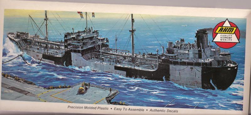
That big block up front is a companionway probably, down to the forward pump room. There's some vents there too, which give away that there's a space down there, and the dry hold is forward. The pump room would be inside of the frames that form the cofferdam, if she has one.

An interesting detail are the hatches on the face of the bridge at the first accomodation deck, two on one side and one on the other. That must be where your catwalks come to. At which point any resemblance to a T2 goes out the window. The US ship has open galleries across the bridge on several levels, this one looks flush, really more modern. It's actually IMHO a pretty modern design compared to the venerable old T2.

Keep posting, this is cool.

Great info, Bondo---you are the man...the ship is so cool and the model so good I bought another:

Fujimi has about 6 or 7 of these kits out and all seem to be the same class of ship with just minor differences in the fittings...since I got the last kit I suspect they have all the same sprues in each kit as several pieces are left over and there are many options. Also, there are several holes that you either leave flashed over or open up according to the specific ship (see parts layout):


Nice plan view:

Notice the different bridge front, boom, mast and lattice work options...

I also just bought their brand-new Argentina Maru liner:

I believe this ship and her sister (Brazil Maru) were converted to the Zuiho and Shoho...


  • Member since
    March 2007
  • From: Carmel, CA
Posted by bondoman on Sunday, July 12, 2009 7:06 PM

Manny you seem to be going Japanese, or else that lattice mast has to go and a bunch of other stuff.

So on that premise, which I'd do too- here's how the distribution system worked on a T2, from which you can surmise how the Japanese might have done it.

There's a whole series of oil holds port/starboard, bow to stern. Like 27. Each one has a manhole for access to clean etc., on a coaming a couple of feet high so that the seal is a little up from the constant deck water. There's a vent pipe that comes out of the side of that, not very large in diameter, runs to a collector running fore/aft down the centerline under the catwalk, and then up the mast to daylight.

There's a manifold (take a bow) of hose connections midships, on each side. On a T2 these are plumbed horizontally into the center, from where a series of very large diameter pipes run fore/ aft to houses where they turn downwards and go into a pumproom, at each end of the holds. These are located along the catwalk.

From the pump room, pipes run in the bottom of the ship to each hold, which is either loaded or emptied from the bottom. Each access cover has a valve wheel near it, connected to a long staff that operates a valve in the bottom of the hold controlling flow.

Your ship is an auxiliary oiler, meaning that when the pumps empty the holds, there are valves in the main ondeck (?) distribution system to which long hoses are attached. These hoses are handled by a series of booms. Your double mast with the lattice looks to have four booms, kind of like a C2, and there looks to be a single staff and boom in the corners as well. Each one would handle a hose. What you need to do is have this baby under way refueling a carrier.

Here's the idea, credit to John Steele.

That big block up front is a companionway probably, down to the forward pump room. There's some vents there too, which give away that there's a space down there, and the dry hold is forward. The pump room would be inside of the frames that form the cofferdam, if she has one.

An interesting detail are the hatches on the face of the bridge at the first accomodation deck, two on one side and one on the other. That must be where your catwalks come to. At which point any resemblance to a T2 goes out the window. The US ship has open galleries across the bridge on several levels, this one looks flush, really more modern. It's actually IMHO a pretty modern design compared to the venerable old T2.

Keep posting, this is cool.

  • Member since
    December 2005
  • From: Seattle, Colorado
Posted by onyxman on Sunday, July 12, 2009 5:45 PM
The oil comes and goes through a big hose which connects to the piping system. I don't see it represented in the boxtop art. The square things are for access to the tanks for gauging the level of the oil and also to allow personnel to get down there for cleaning (after the oil is gone and the space is gas free of course).
  • Member since
    March 2004
  • From: Spartanburg, SC
Posted by subfixer on Saturday, July 11, 2009 7:47 PM
This project is coming along right smartly, Manny. What kind of base are you going to mount her on? Have you figured out how you are going to create the list?

I'm from the government and I'm here to help.

  • Member since
    November 2005
Posted by Anonymous on Saturday, July 11, 2009 12:40 PM
 onyxman wrote:

My first guess about that structure forward was a skylight over a forward pumproom, but on closer inspection I think Bill is right, it's a dry cargo hatch.

So on this tanker, there was room for some dry cargo up front...?  I am guessing that the oil tanks started about where the little square cubes appear on the deck---are these where the liquids were pumped in???

  • Member since
    December 2005
  • From: Seattle, Colorado
Posted by onyxman on Saturday, July 11, 2009 12:26 PM

Well, I wouldn't disparage all cooks on merchant ships. Some of them are truely great, and some are handicapped by the quality of the food supplied by the company.

My first guess about that structure forward was a skylight over a forward pumproom, but on closer inspection I think Bill is right, it's a dry cargo hatch.

The catwalks allow you to bypass all that deck piping, but also because tankers have low freeboard, the main decks are sometimes pretty wet in bad weather.  As for entertainment, before videos, merchant ships had truly amazing collections of paperbacks, with Louis L'Amour westerns being the most popular.  There were also legendary poker games, especially on the passenger ships.  I purposfully never learned how to play so I could actually keep my pay.  Now, with individual DVDs and airconditioning, everybody keeps to their cabins.  If it wasn't for Boat Drills you would never meet some of the crew.

 Fred

  • Member since
    March 2007
  • From: Carmel, CA
Posted by bondoman on Saturday, July 11, 2009 1:07 AM

It's a cargo hatch with a series of hatch covers. Those used to be popular coffee table tops a couple of decades ago, with the recessed handles. Those look way too big, though, but so what.

In a T2 the crew all lived and fed in the stern house. Usually if she was armed there was some arrangement of lean-to shacks or dog houses for the gun crews attached to the prewar-design cabin. The Officers live in the middle structure, so as to have quick access to the bridge, charts, radios and the gyro, and probably to be able to defend themselves from a mutinous crew. They had their meals in the rear however, the wardroom accessible by one of those long catwalks, unless the stewards made the trip forward from the galley back there with trays.

All merchant ships have limited accomodations, or used to. I've done a little of that, it's a nice way to go as you get to mess in the Wardroom and there's usually only a few of you. On the other hand, there's not much to do, and they don't usually feed too well, as Fred can tell you. Plus they take a really long time to get somewhere. The main entertainment is watching the cargo loading, which on a tanker wouldn't be too interesting.

  • Member since
    November 2005
Posted by Anonymous on Saturday, July 11, 2009 12:14 AM
 bondoman wrote:

Your photo studio, apparently, and I know you like it that way so no beef from me. I just notice that all your very fine models, except the chicks, seem to be photog'd in some kind of blue light. Good on, mate.

If/when you cut down the hull, you can give it a list, roll, down at the bow, whatever. Adds all kinds of dynamics to a model on a base.

Ahhhhh...I get you now...Another question: What is the structure on the bow w/ the PE roof?

Also, were the main crew areas in the forward bridge or the aft structure? I also read where some of these Japanese tankers could also carry a modest # of passengers...

  • Member since
    March 2007
  • From: Carmel, CA
Posted by bondoman on Friday, July 10, 2009 11:54 PM

Your photo studio, apparently, and I know you like it that way so no beef from me. I just notice that all your very fine models, except the chicks, seem to be photog'd in some kind of blue light. Good on, mate.

If/when you cut down the hull, you can give it a list, roll, down at the bow, whatever. Adds all kinds of dynamics to a model on a base.

  • Member since
    November 2005
Posted by Anonymous on Friday, July 10, 2009 11:19 PM
 bondoman wrote:
On a T2 you'd have a workout climbing over all the pipes.
Ahhhh, that makes sense...I thought it had something to do with static electricity discharge...what's a blue room?
  • Member since
    March 2007
  • From: Carmel, CA
Posted by bondoman on Friday, July 10, 2009 9:50 PM
On a T2 you'd have a workout climbing over all the pipes.
  • Member since
    November 2005
Posted by Anonymous on Friday, July 10, 2009 7:34 PM
I am about to add more etch...it looks as if there is an elevated catwalk on either side of the forward bridge of the ship---what was the purpose of this? Why couldn't the crew just walk on the deck?
  • Member since
    March 2007
  • From: Carmel, CA
Posted by bondoman on Friday, July 10, 2009 7:27 PM

It all depends on whether or not she's loaded. For your purposes I'd think you want her a big fat loaded target. The freeboard on a T2 is about 11 feet when fully loaded, so you can be the judge.

I looked at a couple of shots of your ship, and the model looks right if she were empty. You can tell because there's a good 8-10 feet of antifouling paint showing when she's as high as that model.

  • Member since
    November 2005
Posted by Anonymous on Friday, July 10, 2009 12:46 PM
 ddp59 wrote:
between water & deck.
So my ship is riding TWICE as high as it should in the water???
  • Member since
    April 2005
Posted by ddp59 on Friday, July 10, 2009 12:16 PM
between water & deck.
  • Member since
    November 2005
Posted by Anonymous on Friday, July 10, 2009 6:57 AM
 bondoman wrote:

Looks good so far although I don't get the Blue Room.

First fix on tanker models I do is to chop out and replace the curved fillet fore/aft of the deck houses. Ships have style, and if you care it's important to get it right.

You can see where that would help, but of course you are sinking it, right?

Second thing, after the fact that you'll never defeat that pathetic attempt at plate variation. Cut the freeboard down by 50%.

Dang---the Japanese vessel looks just like your T-2 !!!  What's a blue room and freeboard?
  • Member since
    March 2007
  • From: Carmel, CA
Posted by bondoman on Friday, July 10, 2009 12:54 AM

Looks good so far although I don't get the Blue Room.

First fix on tanker models I do is to chop out and replace the curved fillet fore/aft of the deck houses. Ships have style, and if you care it's important to get it right.

You can see where that would help, but of course you are sinking it, right?

Second thing, after the fact that you'll never defeat that pathetic attempt at plate variation. Cut the freeboard down by 50%.

  • Member since
    November 2005
Posted by Anonymous on Thursday, July 9, 2009 5:23 PM

Progress. Please comment or I'll do something nasty in your bilge tank...

  • Member since
    November 2005
Posted by Anonymous on Tuesday, July 7, 2009 8:18 PM
hee hee hee...loose lips sink ships---thanks for the info! Should post WIP pics soon...kit went together great----working on PE railings now.
  • Member since
    August 2008
Posted by tankerbuilder on Monday, June 29, 2009 6:26 PM
 Herr MANSTEIN --- If you get a good shot in and it strikes just aft of the midships cofferdam it will most times but not always break in two . The cofferdam was a doubled w/t bulkhead just forward of the engineering spaces and just forward and just aft of the belowdecks areas midships . The cofferdams sometimes were used as extra ballasting tanks and sometimes were even filled with sand to reduce fire hazard when in a collision. The cofferdam sometimes meant the difference in saving a ship and it,s crew as well . The various tanks could be flooded with sea water and cargo carried only in the longitudal midline tanks . iT WAS A MANEUVER USED OFTEN TO KEEP U-BOAT LOSSES DOWN .  If a torpedo struck exactly at the forward cofferdam you usually saw a tanker sink in two halves .The whole trick was to break the tanker,s back . the resultant explosion from the torpex ignited fumes and oil at the impact site ..Why am I ,a tanker captain ,telling you this. Maybe it,s because I wouldve rammed if I could, especially if I had to sail alone .    tankerbuilder
  • Member since
    December 2005
  • From: Seattle, Colorado
Posted by onyxman on Monday, June 29, 2009 12:02 PM
You can break a tanker in two at the dock just by loading it unevenly. I have no idea how they react to a torpedo hit. I guess it depends on where it's hit and whether it's loaded or in ballast.
  • Member since
    November 2005
Posted by Anonymous on Sunday, June 28, 2009 10:21 AM
 bondoman wrote:

What's in a T2.

Forward of the forward coffer dam, which is about where the forecastle starts, there are ballast tanks, on top of which there are cargo holds, ammunition lockers and other stores, plus the chain locker. At main deck level are shops, paint locker, lamp room.

Midships the structure is fresh water tanks at the main deck level with a lot of open pass thru, ofiicers quarters above that; captains quarters, gyro room and radio room above that; and the chart house/wheel house.

In the stern, aft of the cofferdam, which is about where the stern structure begins, there are all of the predictable engineering spaces, ballast tanks, lockers and ammunition storage. At deck level the seamen's quarters and galley stores, above that the engineer's quarters, galley and the crew and officer's mess rooms, and above that the boat deck which has a double high open space for the boiler room, which is above the engine room and directly under the skylight. I'd say the fore/aft walkways got a lot  of use.

I think the conversion to a Allied ship is a reach, and it looks pretty cool the way it is. She's a beaut and very Japanese looking.

Bondo, that's a ton of cool info but I can't follow exactly where you are talking about because I am not familar w/ all of the terminology, such as "cofferdam"? 
  • Member since
    November 2005
Posted by Anonymous on Saturday, June 27, 2009 8:56 PM
 onyxman wrote:

Since you have a model of a Japanese tanker that was torpedoed, and you want to do a scene of a torpedoed tanker, it would of course be best to do the Japanese tanker.

Agree...when I sink a tanker it usually settles level in the water...rarely do they break apart like many cargo-types do...Anyone have any other info on the tendency of tankers to behave as they go down??? 

  • Member since
    December 2005
  • From: Seattle, Colorado
Posted by onyxman on Saturday, June 27, 2009 4:35 PM

I think it looks only generally like a T-2 or T-3. It's a stretch. It looks more like the Ohio, of Operation Pedestal fame.

Since you have a model of a Japanese tanker that was torpedoed, and you want to do a scene of a torpedoed tanker, it would of course be best to do the Japanese tanker.

There are plenty of photos of the S.S. Ohio on the web. You can decide for yourself if your kit is close enough. Patrick Camelleri did a nice 1/600 scratch build of her that you can see in the Model Warships Gallery.

http://www.modelshipgallery.com/gallery/service/tanker/ohio-600-pc/pc-index.html


The Ohio was torpedoed, but not sunk, by the Italian submarine Axum. It was hit by one of 4 torpedoes fired by Lt Cmdr Renato Ferrini in what has got to be one of the most effective spreads in history. The other 3 hit HMS Cairo, twice, and HMS Nigeria. Cairo sank.

The Ohio had two sister ships, the Kentucky and the Oklahoma. Kentucky was sunk by Italian dive bombers and surface ships. Oklahoma was sunk by a U-boat off Savannah.

Yes, Liberties were made into tankers, as well as colliers.   I recall the plans are in the Smithsonian Plans catalogue, but I don't have it here right now. Frank Gerhardt's site has a section designated EC2-S-AW1, but these have the traditional tanker form, with engines aft and a mid-ship bridge.  I'm not sure if these are the tanker variants MSOB referred too or are another type altogether. 

Fred

  • Member since
    November 2005
Posted by Anonymous on Saturday, June 27, 2009 3:16 PM

Some out of the box pics of the pieces...

one-piece hull:

Some of that really nice etch:

  • Member since
    March 2007
  • From: Carmel, CA
Posted by bondoman on Friday, June 26, 2009 5:02 PM

What's in a T2.

Forward of the forward coffer dam, which is about where the forecastle starts, there are ballast tanks, on top of which there are cargo holds, ammunition lockers and other stores, plus the chain locker. At main deck level are shops, paint locker, lamp room.

Midships the structure is fresh water tanks at the main deck level with a lot of open pass thru, ofiicers quarters above that; captains quarters, gyro room and radio room above that; and the chart house/wheel house.

In the stern, aft of the cofferdam, which is about where the stern structure begins, there are all of the predictable engineering spaces, ballast tanks, lockers and ammunition storage. At deck level the seamen's quarters and galley stores, above that the engineer's quarters, galley and the crew and officer's mess rooms, and above that the boat deck which has a double high open space for the boiler room, which is above the engine room and directly under the skylight. I'd say the fore/aft walkways got a lot  of use.

I think the conversion to a Allied ship is a reach, and it looks pretty cool the way it is. She's a beaut and very Japanese looking.

  • Member since
    November 2005
Posted by Anonymous on Friday, June 26, 2009 9:17 AM

Great info, guys!!!  A few more observations/questions:

1) So that's what that latticework is on the left side: a catwalk---I thought it had something to do with the piping of the liquid cargo...

2) Why were their two superstructures on tankers? Was the forward one the bridge and the aft on living/working quarters?

3) Maybe the lack of lifeboats on the Japanese Tanker goes along with their philosophy of life at the time: you get sunk--you go down w/ the ship...

4) I'm not too thrilled with those elevated gun platforms---were these late-war additions---wonder if I could get away w/ leaving them off...  

By the way, although expensive, it is a great kit in terms of quality: great moldings and some excellent etch for the catwalks, etc...


  • Member since
    March 2005
  • From: West Virginia, USA
Posted by mfsob on Friday, June 26, 2009 8:31 AM

Another feature that sets Japanese auxiliaries off is that nation's preference for gun mounts that look more like steel mushrooms than anything else - and the addition of bleached canvas wind dodgers around same that made fine target references, to my eye at least.

Not that it applies to the diorama idea proposed here, but if someone wanted to provoke a lot of head-scratching at a model contest, they could do comparison builts of WW II US and Japanese tankers, and include, on the US side, a Liberty ship. That's right, a Liberty ship. I have the reference somewhere but am still unpacking from a move - a dozen or so Liberty ships were converted into tankers, with NO changes to the outside silouhette. Same number of king posts, cargo booms, etc. Just a few more vents so that, to the submariner's eye, it would appear as just another fat merchantman painted gray in a whole heard of identical ships.

  • Member since
    August 2008
Posted by tankerbuilder on Friday, June 26, 2009 8:08 AM
 HI MANSTEIN ! ----Hey I could be wrong but that looks like a t3-2 to me . they were larger than the t2 by almost 90 feet ! The elongated stern deck and the profile of the central deckhouse is what I,m going by .I could be wrong , but I don,t think so . The deck camber I mentioned earlier is still something you,d have to deal with in larger scales ,so , I don,t think it will be a problem in this scale .The absence of life rafts and life boats in the picture puzzles me though . Just aft of the bridge on both sides is where the standard boats should be . The life rafts and any extra boats are carried in the spaces on the 01 level next to the stack . They sometimes carried extra boats for the enlarged crews on board .Remember , the coast guard or navy supplied the gun crews . This added sometimes as many as 45 to 55 extra hands . The longer stern definitely indicates that it is of early war JAPANESE design.The deck rig indicates this too . SEE , every country had their own ideas on how they should be built !. That is why , just like trains , the allies decided to have some standardization betweem them . Vell , mine KAPITAN/ LEIUTENANT , don,t vaste a torpedo on my oilschiff . This time I carry ze schnapps !!!   tankerbuilder
JOIN OUR COMMUNITY!

Our community is FREE to join. To participate you must either login or register for an account.

SEARCH FORUMS
FREE NEWSLETTER
By signing up you may also receive reader surveys and occasional special offers. We do not sell, rent or trade our email lists. View our Privacy Policy.